EP4480363A1 - Procédé et kit pour l'installation d'une cuvette de douche dans des locaux humides lors de la rénovation de constructions usagées - Google Patents
Procédé et kit pour l'installation d'une cuvette de douche dans des locaux humides lors de la rénovation de constructions usagées Download PDFInfo
- Publication number
- EP4480363A1 EP4480363A1 EP23180135.8A EP23180135A EP4480363A1 EP 4480363 A1 EP4480363 A1 EP 4480363A1 EP 23180135 A EP23180135 A EP 23180135A EP 4480363 A1 EP4480363 A1 EP 4480363A1
- Authority
- EP
- European Patent Office
- Prior art keywords
- shower tray
- wall panel
- floor
- wall
- profile
- Prior art date
- Legal status (The legal status is an assumption and is not a legal conclusion. Google has not performed a legal analysis and makes no representation as to the accuracy of the status listed.)
- Pending
Links
Images


Classifications
-
- A—HUMAN NECESSITIES
- A47—FURNITURE; DOMESTIC ARTICLES OR APPLIANCES; COFFEE MILLS; SPICE MILLS; SUCTION CLEANERS IN GENERAL
- A47K—SANITARY EQUIPMENT; ACCESSORIES THEREFOR, e.g. TOILET ACCESSORIES
- A47K3/00—Baths; Showers; Appurtenances therefor
- A47K3/28—Showers or bathing douches
- A47K3/40—Pans or trays
Definitions
- the subject matter of the invention is a method and a kit for the installation of a shower tray during the renovation of old buildings_according to the preamble of patent claim 1.
- EP 2 182 140 B1 suggests a trough-shaped, bevelled metal part as a shower tray, on whose surrounding flanged edge the wall elements sit. The resulting connection joint must be sealed with a sealant.
- the invention is therefore based on the object of creating a method and a kit for plate-shaped wet room sealing, in which an improved seal between the shower tray and the wall panels adjoining the shower tray is provided.
- the invention is characterized by the technical teaching of the independent patent claim.
- a kit for the installation of a shower tray in sanitary rooms with prefabricated components that can be assembled on site, consisting of at least one shower tray with a shower tray base, at least one wall panel that is sealed to the shower tray via a horizontal floor-side connection joint and a floor wall profile connecting the wall panel to the shower tray, the floor profile leg of which is connected to the underside of the shower tray base. and whose wall profile leg forms a support for the pivoting wall panel, which, when pivoted, applies a lower, floor-side pressure surface to the facing front side of the shower tray floor, creating a contact force and forming the connecting joint.
- An advantageous feature is that a horizontal connection joint on the floor between a shower tray and a wall panel that sits sealed on the shower tray is formed by arranging a connection joint, free of sealant from the visible side, between the wall panel and one end of the shower tray in the connection area.
- connection joint In implementing the technical teaching of the invention, considerable difficulties had to be overcome, which consisted in not simply keeping a floor-side connection joint free of a sealant, but also ensuring that the connection joint was minimal and preferably had a joint width of 0-0.3 mm. It was even possible to make the connection joint invisible and thus preferably have a joint width of 0 mm. In order to enable such a minimal joint width, it was necessary to produce the connection joint under high contact pressure of the associated components in order to minimize it to the required size.
- the high contact pressure of the inner side of the wall panel on the opposite front side of the shower tray base was achieved by using the wall panel in the manner of a two-armed lever, whereby the wall panel was pivoted around the pivot bearing of a floor wall profile connected to the shower tray base. was pivoted.
- the wall panel is therefore used in the manner of a 2-armed lever and the upper, longer lever arm is used to exert the pivoting force generated by the installer's hand pressure, while the shorter lever arm, which is intended to create the floor-side connection joint, achieves a high contact pressure on the opposite end of the shower tray floor in order to form a minimal connection joint.
- the bottom part of the wall panel will be placed under high pressure against the opposite end of the shower tray floor, forming the preferably invisible connection joint there.
- the high contact pressure generated by the leverage ensures that any inaccuracies in the longitudinal extension of the connection joint caused by the component are compensated for by the high contact pressure, thus creating a uniform and ideally invisible connection joint that extends over the entire length.
- the floor-wall profile which is attached to the outside of the wall panel with the pivot bearing, is attached with its horizontal floor profile leg to the underside of the shower tray floor and is connected there to it preferably via load-transferring, elastic sealing connections.
- the vertical floor profile leg of the floor-wall profile has at least one support web directed towards the back of the wall panel, which serves as a pivot bearing for the wall panel that can be pivoted there during assembly, which can be pivoted into an associated position that has not yet been
- the sealing chamber of the floor wall profile which is filled with hardened sealant, can be pivoted in.
- the support web directed against the back of the wall panel on the inside of the vertical wall profile leg acts as a pivot bearing of a two-armed lever, which, according to the lever law, amplifies the swiveling force acting on the wall panel many times over, so that the lower peripheral edge of the wall panel swiveled into the vertical in this way rests against the front side of the shower tray base under great pressure and seals there - preferably without any joints.
- the lower, inward-facing part will preferably be placed seamlessly and preferably without sealant but sealed against the front of the shower tray floor. There are therefore no visible silicone joints that could get dirty.
- the wall panel is made of a water-repellent material and preferably of a cast mineral material. These are tiny, powdery ceramic particles that are a plastic matrix. It has the usual panel thickness in the range between 5-80 mm.
- a water-repellent, cast mineral material other materials can also be used for the wall panel and/or the shower tray base, in particular water-repellent coated wooden panels, plastic panels or multi-layer panels in which at least the inside exposed to moisture is water-repellent.
- the invention therefore also deviates from the conventional form of trough-shaped shower trays and instead uses only a horizontal, plate-shaped shower tray base, which is preferably made of cast mineral material. Consequently, there are no surrounding, projecting edges of shower trays onto which wall panels are attached in a sealed manner in the prior art.
- the invention also allows for a trough-shaped shower tray and only requires that the wall panel to be sealed is attached with its connecting joint to the front side of a horizontal edge of the shower tray.
- the sealing takes place in the area of the vertical front side of the horizontal shower tray base and the lower inside of the wall panel, which is applied to the front side of the shower tray base with high pressure and forms a preferably seamless sealing connection.
- seal refers to minimum joint widths in the range between 0 and 1 mm, but preferably a joint width of 0 mm.
- connection joint formed in the area of the corner connection provides connection surfaces that are inclined at an angle of 90° to one another.
- the invention is not limited to this. It can be provided that the front side of the shower tray base has a slope and the inside of the wall panel, which is pressed against it with a high contact force, has a complementary slope.
- this area of the connection joint there can also be interlocking, complementary grooves or profile webs of the two parts to be connected.
- a method for producing such a sealed, preferably seamless, floor-side corner connection consists in that, in a first process step, the plate-shaped shower tray base is connected to the floor-side, horizontal floor profile leg with the aid of sealing compounds arranged in sealing chambers, wherein the sealing compounds consist of adhesive heaps or adhesive beads of a permanently elastic sealing compound which solidifies when cured but remains permanently elastic.
- connection is made in the factory using the permanently elastic adhesive between the floor profile leg of the floor-wall profile and the bottom side of the shower tray, so that these two parts arrive at the installation site already connected using elastic sealing compounds.
- a screw or wedge or other non-detachable mechanical connection can also be provided.
- a sealing chamber on the inside of the vertical wall profile leg extending into the area of the connection joint is filled with a hardenable, permanently elastic sealant, whereby the sealing chamber in the wall profile leg extends to the front side of the shower tray floor.
- the wall panel is inserted at an angle of, for example, 10 degrees to the vertical with its bottom side in the space between the sealing chamber on the vertical wall profile leg, which is still filled with liquid sealant, and the front side of the shower tray base, so that at least the lower front side of the wall panel protrudes into the sealing chamber.
- the wall panel is pivoted into the vertical position, whereby the back of the wall panel is supported as a pivot bearing on the supporting web of the vertical wall profile leg directed against the back of the wall panel.
- the desired leverage effect is exerted on the lower part of the vertical wall panel, which ensures that the lower part of the wall panel pivots around this profile-side support and rests with its front side on the facing front side of the shower tray floor, thereby forming a preferably invisible and sealed line contact.
- the sealing chamber is filled with a sealant that has not yet set during this swiveling and assembly process, so that during the swiveling process part of the sealant also comes into the area of line contact between the two parts that come into contact with each other and are connected with a high contact force, namely between the front side of the plate-shaped shower tray base and the lower inside of the vertical wall panel. If a transparent sealant is used, it is permitted for it to penetrate into the connection joint and seal it.
- the advantage of the measure according to the invention is that a very high contact pressure is achieved between the lower part of the vertical wall panel and the front side of the shower tray floor using a tool-free lever effect, which is not possible with other measures.
- a support forming the pivot bearing is present in the area of the inside of the vertical wall profile leg, which forms the desired two-armed lever from the wall panel.
- the pivot bearing is preferably designed as a horizontally directed support web formed on the inside of the vertical wall profile leg.
- other parts of the profile can also be present to form the pivot bearing.
- the support web it is possible to provide a wedge-shaped element on the inside of the wall profile leg, which forms the pivot bearing and at the same time forms an insertion bevel for the insertion of the bottom side of the wall panel into the space between the front side of the shower tray base and the inside of the vertical wall profile leg.
- the insertion bevel is advantageously directed towards the profile-side sealing chamber, so that a safe insertion of the bottom side of the wall panel into the sealing chamber is guaranteed.
- the invention is not limited to the fact that a connection is already made in the factory between the bottom side of the shower tray base and the bottom profile leg of the floor-wall profile. However, this is preferred. In the DIY market, these parts (shower tray base, floor-wall profile and associated sealing compounds) can also be sold and provided as separate components.
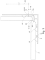
- kit 1 which consists of a vertical wall panel 3, which is connected to another wall panel 4 at a corner via a vertical corner connection (not shown in detail). Both wall panels 3, 4 are sealed to a shower tray base 2, which is part of a sanitary cell.
- a floor-wall profile 6 is present as a further part of the kit 1, which preferably consists of an extruded aluminum profile and consists of two legs that are perpendicular to each other, namely a floor profile leg 7 and a wall profile leg 8 that is connected perpendicularly to it.
- the present drawing description describes a corner connection between the front side of the shower tray base 2 and one wall panel 3.
- the floor profile leg 7 is already connected to the underside of the shower tray floor 2 in the factory via the permanently elastic sealing compounds 13.
- the adhesive does not end up in an undefined widened state when the permanently elastic sealing compound 13 is applied, for example via a cartridge or when applied via permanently elastic sealing tapes.
- the stop webs 9 therefore also serve as a stop guide for the cartridge or as a stop limit for permanently elastic sealing tapes. They also serve to ensure that there is still free space in the space between the stop web 9 and the support web 10 spaced apart from it, in order to ensure that the sealing compound 13 does not tear open or break off when the sealing compound 13 moves.
- sealing chamber 12 It therefore has a certain amount of movement in the respective sealing chamber 12 and it is considered preferable that the sealing chamber 12 is not completely filled with sealing compound 13, but that spaces are created in between which allow the sealing compound 13 to move, in order to prevent it from tearing off under shear load.
- sealing tapes are used instead of the permanently elastic sealing compound that is dispensed via a cartridge
- the profile of the sealing tapes can have various shapes.
- such a sealing tape can be rectangular or square, whereby it should in any case have an excess whose height extends beyond the height of the support web 10 in order to enable compression of the sealing tape during assembly.
- the shape of the sealing strip can be trapezoidal, square, rectangular, oval or in any other profile shape, whereby the main focus here is that not the entire space of the sealing chamber 12 is filled, but only a part, in order to enable the shower tray base 2 to move in the direction of its longitudinal extension without the sealing compound tearing or breaking open.
- the sealing compounds 13, 13a shown preferably extend over the entire width of the shower tray base and the wall panel 3, 4.
- the front side 24 of the shower tray base 2 also engages into the profile-side sealing chamber 21, whereby the same previously described physical conditions apply to the sealing compound 13a as for the sealing compound 13, so that the lower floor-side front side of the shower tray base 2 engages over its full length and with its full volume into the permanently elastic sealing compound 13a of the sealing chamber 21.
- the invention now concerns the fact that at least a part of the front side 24 of the shower tray base 2 is connected to the inside of the wall panel 3 via a preferably invisible connection joint 26 with a high contact pressure, which is preferably carried out by the following technical teaching.
- the wall panel 3' is first pivoted in the pivoted position with its lower bottom side into the profile-side sealing chamber 21, so that on the lower foot side inner surface of the wall panel 3 forms a pressure surface 17 in order to prepare for the invisible connection joint 26 to be arranged there.
- the sealing chamber 21 receiving the foot of the wall panel 3 is filled during assembly with a preferably transparent sealing compound 13a which has not yet hardened in order to allow a certain displacement of the sealing compound when pivoting in.
- the wall panel 3' has been pivoted in the direction shown in Figure 2 shown position, the lower, inward-facing side of the wall panel 3 with the pressure surface 17 already rests against the front side 24 of the shower tray base.
- the pivot angle 23 which is preferably in the range between 10 and 30 degrees
- the outside of the wall panel 3 pivots like a lever, which rests against the inner support web 10 in the area of the wall profile leg 8 and acts as a two-armed lever.
- the upper lever arm 28 is long and is pivoted by the fitter in the direction of arrow 14 by the pivot angle 23, whereby the shorter lever arm 18 moves with high contact force against the front side 24 of the shower tray base 2.
- a sealing compound 13 can also be applied in the area of the vertical wall profile leg 8 for connection to the outside of the wall panel 3, whereby this sealing compound 13 can also be omitted because it is sufficient to provide the transparent sealing compound 13a arranged in the sealing chamber 21 for sealing the connection joint 26.
- the Figure 3 shows a variation of the Figure 2 , where it can be seen that in another embodiment it is possible to profile the front side 24 of the shower tray base 2.
- the length of the lever arm 18 between the support web 10 serving as a support 16 and the pivot point 17 can be designed in any way. It is preferred if its length is approximately in the range of 3 to 20 mm.
- the length of the lower lever arm 18 can also be adjusted according to its distance. As a result, the inner base side of the wall panel 3 is pressed onto the opposite end face 24 of the shower tray base 2, possibly with slight plastic and/or elastic deformation.
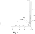
- the Figure 4 shows that instead of a horizontal support web 10, which is arranged on the inside of the wall profile leg 8 and is directed inwards, there could also be a wedge-shaped web which acts as an abutment 20 for the two-armed lever 18, 28 formed from the wall panel 3. Instead of the wedge surface, rounded surfaces can also be used to form an insertion bevel for the bottom side of the wall panel 3.
- the Figure 4 therefore shows such a rounded abutment 20, which is approximately wedge-shaped and has an upper insertion bevel 25, which facilitates the insertion of the lower end of the wall panel 3 into the associated profile-side sealing chamber 21.
- the two parts 2, 3 which abut each other and form the linear seal can have an overlap height of 1 to 8 mm.
Landscapes
- Health & Medical Sciences (AREA)
- Public Health (AREA)
- Epidemiology (AREA)
- General Health & Medical Sciences (AREA)
- Residential Or Office Buildings (AREA)
Priority Applications (1)
| Application Number | Priority Date | Filing Date | Title |
|---|---|---|---|
| EP23180135.8A EP4480363A1 (fr) | 2023-06-19 | 2023-06-19 | Procédé et kit pour l'installation d'une cuvette de douche dans des locaux humides lors de la rénovation de constructions usagées |
Applications Claiming Priority (1)
| Application Number | Priority Date | Filing Date | Title |
|---|---|---|---|
| EP23180135.8A EP4480363A1 (fr) | 2023-06-19 | 2023-06-19 | Procédé et kit pour l'installation d'une cuvette de douche dans des locaux humides lors de la rénovation de constructions usagées |
Publications (1)
| Publication Number | Publication Date |
|---|---|
| EP4480363A1 true EP4480363A1 (fr) | 2024-12-25 |
Family
ID=86899102
Family Applications (1)
| Application Number | Title | Priority Date | Filing Date |
|---|---|---|---|
| EP23180135.8A Pending EP4480363A1 (fr) | 2023-06-19 | 2023-06-19 | Procédé et kit pour l'installation d'une cuvette de douche dans des locaux humides lors de la rénovation de constructions usagées |
Country Status (1)
| Country | Link |
|---|---|
| EP (1) | EP4480363A1 (fr) |
Citations (4)
| Publication number | Priority date | Publication date | Assignee | Title |
|---|---|---|---|---|
| DE7429246U (de) | 1974-08-30 | 1974-12-05 | Mengeringhausen M | Bausatz für Fliesen-Fertigwandelemente |
| US4541132A (en) * | 1983-05-03 | 1985-09-17 | Long Jack C | Shower pan |
| US5913777A (en) * | 1997-05-12 | 1999-06-22 | Tile Redi, Ltd. | Pre-fabricated shower module and method of shower construction |
| EP2182140B1 (fr) | 2008-11-03 | 2016-12-28 | Geberit International AG | Kit destiné à une cellule sanitaire et cellule sanitaire correspondante |
-
2023
- 2023-06-19 EP EP23180135.8A patent/EP4480363A1/fr active Pending
Patent Citations (4)
| Publication number | Priority date | Publication date | Assignee | Title |
|---|---|---|---|---|
| DE7429246U (de) | 1974-08-30 | 1974-12-05 | Mengeringhausen M | Bausatz für Fliesen-Fertigwandelemente |
| US4541132A (en) * | 1983-05-03 | 1985-09-17 | Long Jack C | Shower pan |
| US5913777A (en) * | 1997-05-12 | 1999-06-22 | Tile Redi, Ltd. | Pre-fabricated shower module and method of shower construction |
| EP2182140B1 (fr) | 2008-11-03 | 2016-12-28 | Geberit International AG | Kit destiné à une cellule sanitaire et cellule sanitaire correspondante |
Similar Documents
| Publication | Publication Date | Title |
|---|---|---|
| DE10233731A1 (de) | Anordnung von Bauteilen mit Verbindungselementen | |
| DE1658864A1 (de) | Dehnungsfugenabdeckung | |
| AT518808B1 (de) | Glashalter und Verfahren zur Montage hierfür | |
| DE102015007267A1 (de) | Verbindungselement für Wandbauelemente | |
| EP0828037A2 (fr) | Profilé de bordure pour balcons ou terrasses recouverts par des carreaux | |
| DE202013011085U1 (de) | Anputzleiste, Leiste und Abschlussschiene | |
| DE19520723C2 (de) | Schalungselement | |
| DE10262101B4 (de) | Dämmstoffplatte | |
| DE3312150C2 (fr) | ||
| EP4365400B1 (fr) | Joint de socle sur un plan et ensemble fenêtre | |
| EP4480363A1 (fr) | Procédé et kit pour l'installation d'une cuvette de douche dans des locaux humides lors de la rénovation de constructions usagées | |
| DE10237076A1 (de) | Plattenverband aus Platten aus einem Gipswerkstoff und Verfahren zum Herstellen eines Plattenverbandes | |
| EP0198157A2 (fr) | Liste d'un joint de dilatation en matière plastique, spécialement pour le joint de bordure d'une construction de plancher | |
| DE1994822U (de) | Abdichtung fuer dehnungsfugen in bauwerken. | |
| DE102004008831B4 (de) | Profil zum Abdecken von Dämmschichten | |
| DE102010003480B4 (de) | Schwundfugenprofil sowie Fußbodenkonstruktion | |
| DE60009125T2 (de) | Verkleidungselement mit ineinandergreifenden teilen die eine fuge bilden und verfahren zur herstellung | |
| DE29612763U1 (de) | Holzhaus und zu dessen Herstellung bestimmte Wandtafel | |
| DE102013013074A1 (de) | Zargenkonstruktion zum Anschluss eines Fenster- oder Türrahmens an eine Gebäudewand | |
| DE2905238A1 (de) | Unterkonstruktion | |
| DE3729378A1 (de) | Arbeitsplatteneinheit | |
| EP1688577B1 (fr) | Languette de raccord pour fixer des cadres de fenêtre ou porte à un cadre de base ou à un mur | |
| EP0709530A1 (fr) | Profilé d'extrémité pour balcons, terrasses et similaires et procédé pour sa pose | |
| DE19618587C2 (de) | Verfahren zum Errichten einer Unterkonstruktion und dafür geeignetes Dachausbauelement | |
| DE2157362A1 (de) | Verkleidung fuer fassaden, waende und decken |
Legal Events
| Date | Code | Title | Description |
|---|---|---|---|
| PUAI | Public reference made under article 153(3) epc to a published international application that has entered the european phase |
Free format text: ORIGINAL CODE: 0009012 |
|
| STAA | Information on the status of an ep patent application or granted ep patent |
Free format text: STATUS: THE APPLICATION HAS BEEN PUBLISHED |
|
| AK | Designated contracting states |
Kind code of ref document: A1 Designated state(s): AL AT BE BG CH CY CZ DE DK EE ES FI FR GB GR HR HU IE IS IT LI LT LU LV MC ME MK MT NL NO PL PT RO RS SE SI SK SM TR |
|
| STAA | Information on the status of an ep patent application or granted ep patent |
Free format text: STATUS: REQUEST FOR EXAMINATION WAS MADE |
|
| 17P | Request for examination filed |
Effective date: 20250228 |