EP4480512A1 - Verbinder für eine milchausdrückvorrichtung - Google Patents
Verbinder für eine milchausdrückvorrichtung Download PDFInfo
- Publication number
- EP4480512A1 EP4480512A1 EP23180826.2A EP23180826A EP4480512A1 EP 4480512 A1 EP4480512 A1 EP 4480512A1 EP 23180826 A EP23180826 A EP 23180826A EP 4480512 A1 EP4480512 A1 EP 4480512A1
- Authority
- EP
- European Patent Office
- Prior art keywords
- connector
- expression kit
- expression
- kit
- shape
- Prior art date
- Legal status (The legal status is an assumption and is not a legal conclusion. Google has not performed a legal analysis and makes no representation as to the accuracy of the status listed.)
- Withdrawn
Links
Images



Classifications
-
- A—HUMAN NECESSITIES
- A01—AGRICULTURE; FORESTRY; ANIMAL HUSBANDRY; HUNTING; TRAPPING; FISHING
- A01J—MANUFACTURE OF DAIRY PRODUCTS
- A01J5/00—Milking machines or devices
-
- A—HUMAN NECESSITIES
- A61—MEDICAL OR VETERINARY SCIENCE; HYGIENE
- A61M—DEVICES FOR INTRODUCING MEDIA INTO, OR ONTO, THE BODY; DEVICES FOR TRANSDUCING BODY MEDIA OR FOR TAKING MEDIA FROM THE BODY; DEVICES FOR PRODUCING OR ENDING SLEEP OR STUPOR
- A61M1/00—Suction or pumping devices for medical purposes; Devices for carrying-off, for treatment of, or for carrying-over, body-liquids; Drainage systems
- A61M1/06—Milking pumps
-
- A—HUMAN NECESSITIES
- A61—MEDICAL OR VETERINARY SCIENCE; HYGIENE
- A61M—DEVICES FOR INTRODUCING MEDIA INTO, OR ONTO, THE BODY; DEVICES FOR TRANSDUCING BODY MEDIA OR FOR TAKING MEDIA FROM THE BODY; DEVICES FOR PRODUCING OR ENDING SLEEP OR STUPOR
- A61M1/00—Suction or pumping devices for medical purposes; Devices for carrying-off, for treatment of, or for carrying-over, body-liquids; Drainage systems
- A61M1/06—Milking pumps
- A61M1/062—Pump accessories
-
- A—HUMAN NECESSITIES
- A61—MEDICAL OR VETERINARY SCIENCE; HYGIENE
- A61M—DEVICES FOR INTRODUCING MEDIA INTO, OR ONTO, THE BODY; DEVICES FOR TRANSDUCING BODY MEDIA OR FOR TAKING MEDIA FROM THE BODY; DEVICES FOR PRODUCING OR ENDING SLEEP OR STUPOR
- A61M1/00—Suction or pumping devices for medical purposes; Devices for carrying-off, for treatment of, or for carrying-over, body-liquids; Drainage systems
- A61M1/06—Milking pumps
- A61M1/062—Pump accessories
- A61M1/064—Suction cups
-
- A—HUMAN NECESSITIES
- A61—MEDICAL OR VETERINARY SCIENCE; HYGIENE
- A61M—DEVICES FOR INTRODUCING MEDIA INTO, OR ONTO, THE BODY; DEVICES FOR TRANSDUCING BODY MEDIA OR FOR TAKING MEDIA FROM THE BODY; DEVICES FOR PRODUCING OR ENDING SLEEP OR STUPOR
- A61M1/00—Suction or pumping devices for medical purposes; Devices for carrying-off, for treatment of, or for carrying-over, body-liquids; Drainage systems
- A61M1/06—Milking pumps
- A61M1/062—Pump accessories
- A61M1/067—Pump accessories with means for hands-free operation
-
- A—HUMAN NECESSITIES
- A61—MEDICAL OR VETERINARY SCIENCE; HYGIENE
- A61M—DEVICES FOR INTRODUCING MEDIA INTO, OR ONTO, THE BODY; DEVICES FOR TRANSDUCING BODY MEDIA OR FOR TAKING MEDIA FROM THE BODY; DEVICES FOR PRODUCING OR ENDING SLEEP OR STUPOR
- A61M1/00—Suction or pumping devices for medical purposes; Devices for carrying-off, for treatment of, or for carrying-over, body-liquids; Drainage systems
- A61M1/06—Milking pumps
- A61M1/069—Means for improving milking yield
-
- A—HUMAN NECESSITIES
- A61—MEDICAL OR VETERINARY SCIENCE; HYGIENE
- A61M—DEVICES FOR INTRODUCING MEDIA INTO, OR ONTO, THE BODY; DEVICES FOR TRANSDUCING BODY MEDIA OR FOR TAKING MEDIA FROM THE BODY; DEVICES FOR PRODUCING OR ENDING SLEEP OR STUPOR
- A61M1/00—Suction or pumping devices for medical purposes; Devices for carrying-off, for treatment of, or for carrying-over, body-liquids; Drainage systems
- A61M1/71—Suction drainage systems
-
- A—HUMAN NECESSITIES
- A61—MEDICAL OR VETERINARY SCIENCE; HYGIENE
- A61M—DEVICES FOR INTRODUCING MEDIA INTO, OR ONTO, THE BODY; DEVICES FOR TRANSDUCING BODY MEDIA OR FOR TAKING MEDIA FROM THE BODY; DEVICES FOR PRODUCING OR ENDING SLEEP OR STUPOR
- A61M39/00—Tubes, tube connectors, tube couplings, valves, access sites or the like, specially adapted for medical use
- A61M39/22—Valves or arrangement of valves
- A61M39/24—Check- or non-return valves
-
- F—MECHANICAL ENGINEERING; LIGHTING; HEATING; WEAPONS; BLASTING
- F16—ENGINEERING ELEMENTS AND UNITS; GENERAL MEASURES FOR PRODUCING AND MAINTAINING EFFECTIVE FUNCTIONING OF MACHINES OR INSTALLATIONS; THERMAL INSULATION IN GENERAL
- F16L—PIPES; JOINTS OR FITTINGS FOR PIPES; SUPPORTS FOR PIPES, CABLES OR PROTECTIVE TUBING; MEANS FOR THERMAL INSULATION IN GENERAL
- F16L41/00—Branching pipes; Joining pipes to walls
- F16L41/08—Joining pipes to walls or pipes, the joined pipe axis being perpendicular to the plane of a wall or to the axis of another pipe
-
- A—HUMAN NECESSITIES
- A61—MEDICAL OR VETERINARY SCIENCE; HYGIENE
- A61M—DEVICES FOR INTRODUCING MEDIA INTO, OR ONTO, THE BODY; DEVICES FOR TRANSDUCING BODY MEDIA OR FOR TAKING MEDIA FROM THE BODY; DEVICES FOR PRODUCING OR ENDING SLEEP OR STUPOR
- A61M39/00—Tubes, tube connectors, tube couplings, valves, access sites or the like, specially adapted for medical use
- A61M39/10—Tube connectors; Tube couplings
- A61M2039/1027—Quick-acting type connectors
-
- A—HUMAN NECESSITIES
- A61—MEDICAL OR VETERINARY SCIENCE; HYGIENE
- A61M—DEVICES FOR INTRODUCING MEDIA INTO, OR ONTO, THE BODY; DEVICES FOR TRANSDUCING BODY MEDIA OR FOR TAKING MEDIA FROM THE BODY; DEVICES FOR PRODUCING OR ENDING SLEEP OR STUPOR
- A61M2209/00—Ancillary equipment
- A61M2209/08—Supports for equipment
- A61M2209/088—Supports for equipment on the body
Definitions
- the invention relates to a connector for use in an expression kit for expressing milk from a mammalian breast, the connector being configured to be coupled to a source of negative pressure.
- the invention also relates to an expression kit, and an expression system, both for use with the connector.
- Such a connector, expression kit, and expression system are known from, for instance, WO2021191637A1 .
- WO2021191637A1 discloses a breast pump system for expressing milk from a human female breast, the system comprising at least one wearable milk expression kit connected via a tube to a combined external air pump and control unit.
- Each milk expression kit comprises: (a) a breast shield made up of a breast flange and a nipple tunnel; (b) a flexible diaphragm that is configured to prevent milk from reaching the external air pump; (c) an outer shell that is configured to removably attach to the breast shield, such that, when attached, the breast shield and outer shell form a vessel for collecting milk; and (d) a diaphragm cap that is configured to be secured over the diaphragm, forms part of the front face of the outer shell, and includes a port connected to the tube.
- WO2021191637A1 also discloses that, in the terms used in WO2021191637A1 , the diaphragm cap is omnidirectional and can be rotated against the outer shell to adjust the position of the port on the outer shell and hence the position and direction of the tube.
- this object is realised in that the connector or the expression kit or both are configured such that the connector and the expression kit can be coupled to each other such that the connector can have an orientation selected from a plurality of discrete orientations relative to a housing of the expression kit.
- the invention is based on the insight that the known breast pump system can be simplified if the connector can assume a plurality of discrete positions relative to the housing of the expression kit instead of being omnidirectional as the diaphragm cap in WO2021191637A1 .
- the connector comprises a connector shape configured to provide discrete orientations in which the connector and the expression kit can be coupled to each other.
- the connector shape comprises the shape of a part of the connector that is inserted into an inner volume of the expression kit.
- the connector shape comprises the shape of a part of the connector that completes an outer contour of the expression kit, i.e that is flush with the housing of the expression kit once the connector and the expression kit have been coupled to each other.
- the connector shape may be a shape of the connector or of a part of the connector.
- the term 'connector shape' not only includes the shape of a body comprised in a connector, but may alternatively or additionally also include the arrangement relative to each other of, for instance, connecting interfaces configured to couple a connector and an expression kit to each other.
- connecting interfaces configured to couple a connector and an expression kit to each other.
- two protrusions on opposite sides of a circular circumference of a disk-shaped connector can cooperate with two matching indentations in a receiver (for receiving the connector) comprised in an expression kit.
- the connector is disk-shaped, i.e. round in a plane, and as such can be rotated over any angle in this plane, the provision of discrete elements provides for discrete orientations of the connector relative to the expression kit.
- three protrusions around the circular circumference cooperating with matching indentations on an expression kit would provide three discrete orientations for the connector.
- Such a set of three protrusions will define a triangle between them, resulting in a triangular connector shape. If the three protrusions are evenly spaced, along the circular circumference, they define an equilateral triangle.
- a pair of protrusions may also cooperate with multiple pairs of matching indentations (pairs being defined by indentations on opposite sides of the circumference of an opening matching the connector) resulting in more than two possible discrete orientations for the connector.
- protrusions are on the connector and indentations are on an expression kit.
- Protrusions may be used on the expression kit and matching indentations may be used on a connector.
- matching shapes or elements other than protrusions and indentations may be used, as long as they enable a connector and an expression kit to be coupled to each other (if they would not, they would not be matching; for instance, flexible finger-like elements may be used that can extend from a connector or expression kit into matching openings in an expression kit or connector respectively).
- the connector shape comprises a non-circular shape.
- the non-circular connector shape is ellipse-shaped.
- the non-circular connector shape is polygonal.
- the polygonal connector shape is triangular, rectangular, square, rhomboid, pentagonal, or hexagonal.
- the non-circular shape may be the shape of a body comprised in a connector.
- the connector comprises a hexagonal body to be inserted into a receiver comprised in a corresponding expression kit, wherein the receiver has a kit shape matching the connector shape.
- the non-circular shape may be the shape of connecting interfaces comprised in a connector. For instance, five protrusions evenly spaced along a circular circumference of a disk-shaped connector would define a pentagon between them.
- the connector comprises a wall portion comprising a port for coupling the connector to a tube for communicating negative pressure to the connector, wherein the wall portion defines a part of an outer contour of an expression kit when the connector and expression kit are coupled to each other, wherein the port defines a direction, and wherein said direction is not perpendicular to the wall portion.
- the wall portion may comprise an opening and the port is accessible through the opening.
- the port may be in the wall portion.
- the port may be extending from the wall portion.
- This example has the additional benefit that changing the orientation of the wall portion will change the orientation of the port. This is especially true for changes in the orientation of the wall portion along an axis perpendicular to the wall portion. This example provides an easy way to change the direction of a tube coupled to the port.
- a connector with a curved wall portion and a port perpendicular to the curved wall portion may be used to allow a user to change the position, the orientation, or the position and orientation of a port relative to an expression it).
- the connector is configured such that changing the orientation of the connector in an expression kit from one orientation to a different orientation defines an axis of rotation and that the port is not positioned on this axis.
- This example has the benefit that changing the orientation of the connector in an expression kit will change the position of the port relative to the expression kit.
- This helps in managing a tube connected to the port. For instance, if the port is positioned along a side of the wall portion, such as when the port is positioned at or near the halfway point of a side, or if the port is positioned at a corner of the wall portion (for instance at a corner of a triangular, square, rhomboid, pentagonal, or hexagonal wall portion), changing the orientation of the connector relative to its expression kit will change to position of the port relative to the expression kit. If the port defines a direction that is not perpendicular to the outer contour, changing the orientation of the wall portion will not only change the position of the port, but also the orientation of the port. This again helps a user to manage tubing.
- the connector consists of a single piece.
- This example has the additional benefit that it is easy to manufacture. It does not require assembly.
- the object of the invention is also realized by an expression kit comprising the above connector.
- the expression kit comprises a receiver for receiving the connector, wherein the receiver comprises a kit shape matching the connector shape.
- the connector shape comprises the shape of a part of the connector that is inserted into inner volume of the expression kit and the kit shape matches the connector shape.
- the connector shape comprises the shape of a part of the connector that is flush with the housing of the expression kit once the connector and the expression kit have been coupled to each other and the kit shape matches the connector shape.
- the connector shape relates to the relative positions on the connector of interfaces for coupling the connector to an expression kit and the kit shape relates to the relative positions on the expression kit of interfaces for coupling the expression kit to a connector with a matching connector shape.
- the expression kit is configured to be coupled to the connector such that, after coupling, the connector is located at a position facing away from a user's breast during use.
- a connector does not obstruct a user's view if the expression kit is configured to be coupled to the connector such that, after coupling, the connector is located at a position that does not lie in a user's field of view when, during use of the expression kit, the user looks at the expression kit.
- the connector may be at a position that faces away from a user's torso during use.
- the connector may be at a position that faces in the direction of the other breast of a human female user.
- the connector may be at a position that faces away from the other breast of a human female user.
- the expression kit comprising the connector is configured such that, during use, the connector at least partially defines a pumping volume, the pumping volume defining a volume for receiving negative pressure from a source of negative pressure when the connector is coupled to the source of negative pressure.
- This example has the additional benefit that a user gets access to one or more parts of the expression kit for cleaning once the connector has been uncoupled from the rest of the expression kit.
- the expression kit is configured to fit inside a bra.
- This example has the additional benefit that it provides a convenient form factor so that the expression kit can be worn in a bra.
- the form factor is aesthetically pleasing and, by enabling use in a bra, provides a user with a certain degree of mobility, allowing the user to move around while using the expression kit.
- the object of the invention is also realized by an expression system comprising the above expression kit.
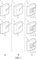
- Fig. 1 schematically shows examples of connectors according to the invention.
- Column A in Fig. 1 schematically shows examples of connectors 1 that comprise ports 5 that protrude from wall portions 10.
- Ports 5 allow connectors 1 to be coupled to tubing (not shown in Fig. 1 ) for fluidly connecting connectors 1 to sources of negative pressure (not shown in Fig. 1 ).
- Ports 5 shown in the drawings in columns Band C in Fig. 1 serve the same purpose.
- port 5 protrudes perpendicularly from wall portion 10.
- the direction in which port 5 extends from wall portion 10 is at a 90° angle with the wall portion 10.
- port 5 protrudes non-perpendicularly from wall portion 10.
- the direction in which port 5 extends from wall portion 10 is at an angle unequal to 90° with wall portion 10.
- ports 5 comprise plugs.
- FIG. 1 schematically shows examples of connectors 1 that are comprised within the body of the connectors 1, without protruding from wall portions 10.
- port 5 extends perpendicularly relative to the wall portion 10. The direction in which port 5 extends has a 90° angle relative to the wall portion 10.
- port 5 extends non-perpendicularly relative to wall portion 10. The direction in which port 5 extends has an angle unequal to 90° relative to the wall portion 10.
- ports 5 comprise holes.
- FIG. 1 schematically shows examples of connectors 1 that comprise recesses 15 in wall portions 10, wherein the ports 5 are positioned within the recesses 15.
- recesses 15 are defined by openings in wall portions 10, sidewalls 20, and base surfaces which, in the examples shown, are parallel to wall portions 10.
- the recesses 15 comprise rectangular openings in wall portions 10.
- the recesses 15 comprise openings that have other shapes, for instance circular, oval or triangular shapes.
- port 5 extends in a direction that is perpendicular to wall portion 10. The direction in which port 5 extends has a 90° angle relative to the wall portion 10.
- port 5 extends in a direction that is not perpendicular relative to the wall portion 10. In the middle drawing in column C, port 5 port 5 extends non-perpendicularly relative to wall portion 10. The direction in which port 5 extends has an angle unequal to 90° relative to the wall portion 10. In the lower drawing in column C, port 5 extends from a side wall 20. In the example shown, port 5 extends perpendicularly from the side wall 20. It will be clear that in another example a port 5 may extend non-perpendicularly from a side wall 20. In all drawings in column C, ports 5 comprise plugs. However, it will be clear that ports 5 in column C might alternatively comprise holes extending into the base surfaces or the sidewalls 20.
- Such holes may extend in directions that are either perpendicular or non-perpendicular to the base surfaces or the sidewalls 20.
- ports 5 do not extend the planes defined by wall portions 10. However, it will be clear that in alternative examples the ports 5 may extend from the recesses 15 beyond the planes defined by wall portions 10.
- Fig. 1 all connectors 1 comprise ports 5 extending from or within bodies having rectangular shapes.
- the connectors 1 can be coupled to the expression kits in four discrete orientations.
- rectangular shapes including square shapes, are not the only shapes providing such pluralities of discrete orientations.
- the bodies of connectors 1 have polygonal shapes, for instance, triangular, rhomboid, pentagonal, or hexagonal shapes.
- wall portions 10 are flat. However, in examples other than those shown in Fig. 1 , wall portions 10 are curved (in the sense that at least a surface this is an out surface during use is curved), for instance to complete curved outer surfaces of expression kits. In such instances, whether or not a port extends perpendicularly or non-perpendicularly relative to a wall portion 10 has to be assessed locally at the position of the port. If a port extends from a base surface of a recess or from a side wall of a recess, whether or not the port extends perpendicularly or non-perpendicularly relative to the base surface or side wall has to be assessed locally at the position of the port.
- Fig. 2 schematically shows further examples of connectors according to the invention.
- Both drawings in Fig. 2 schematically show frontal views connectors 1.
- the connectors 1 comprise ports 5 extending from sidewalls within recesses 15. In both drawings the ports 5 extend from or within bodies having square shapes. So far, the connectors 1 are similar to the example shown in the lower drawing in column C in Fig. 1 . However, while the recess 15 in the lower drawing in column C in Fig. 1 has a rectangular opening, the recesses 15 in the drawings in Fig. 2 have circular openings.
- FIG. 1 A difference between the example shown in the lower drawing in column C in Fig. 1 and the examples shown in Fig. 2 is that in the example in Fig. 1 port 5 is on or near a central axis perpendicular to the wall portion 10.
- ports 5 are positioned off-axis relative to the central axes 25 perpendicular to the wall portions 10.
- the square-shaped bodies of the connectors 1 in Fig. 2 provide four discrete orientations in which the connectors 1 can be received in corresponding receivers comprised in expression kits. The four discrete orientations are obtained by rotating the connectors 1 around the axes 25. Because the positions of ports 5 in Fig.
- port 5 is positioned at a corner of the square-shaped body of the connector 1.
- port 5 is positioned along a side of the square-shaped body of the connector 1.
- port 5 is positioned at the midpoint of one side of the body of the connector 1.
- the bodies of the connectors 1 may have polygonal shapes, for instance triangular, rhomboid, pentagonal, or hexagonal shapes.
- ports 5 may be positioned at corners or along sides of such bodies.
- Ports 5 on bodies having non-polygonal shapes, like oval shapes, may similarly be positioned off a central axis, along a side of the body or at or near an extremity of a minor or major axis.
- each of the ports 5 discussed in relation to Fig. 1 may be positioned off the central axes of the bodies of the connectors 1 discussed in relation to Fig. 1 if one wants rotation of the bodies along the central axes to change the positions or the positions and orientations of the ports 5 relative to expression kits in which the connectors are received.
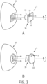
- FIG. 3 schematically shows examples of expression kits according to the invention as well as a further example of a connector according to the invention.
- Drawing A in Fig. 3 schematically shows a connector 1 comprising a part 30 comprising port 5 within recess 15 in a configuration that is similar to the configuration shown in drawing A in Fig. 2 .
- the part 30 comprises a square connector shape.
- the connector 1 further comprises a cylindrically-shaped part 33. Because of the square connector shape and a receiver 40 with a square kit shape matching the square connector shape on the expression kit 35, connector 1 can be coupled to the expression kit 35 in four different, discrete orientations. The four orientations are obtained by rotating connector 1 as indicated by the double-headed circular arrow.
- port 5 changes both its position and its orientation as the orientation of connector 1 is changed from one orientation to another. Being able to change the position or the position and orientation of port 5 allows a user to manage the position respectively the position and orientation of tubing that can be coupled to the port 5 to fluidically couple the port 5 to a source of negative pressure. In this way, a user can select a preferred configuration.
- surface 10 is flush with the neighboring outer surface of the expression kit. Obviously, this is not essential.
- Drawing B in Fig. 3 schematically shows a connector 1 comprising a circular-shaped part, which comprises port 5 extending non-perpendicularly from wall portion 10.
- the connector 1 further comprises a part 30 comprising a triangular connector shape. Because of the triangular connector shape and a receiver 45 with a triangular kit shape matching the triangular connector shape on the expression kit 35, connector 1 can be coupled to the expression kit 35 in three different, discrete orientations. The three orientations are obtained by rotating connector 1 as indicated by the double-headed circular arrow.
- port 5 changes both its position and its orientation as the orientation of connector 1 is changed from one orientation to another.
- the connectors 1 comprise parts comprising connector shapes that enable pluralities of discrete orientations of connectors 1 relative to expression kits 35 when the connectors 1 and expression kits 35 are coupled to each other.
- Connector shapes do not only include shapes of whole bodies like the square-shaped part 30 in drawing A in Fig. 3 or the triangular-shaped part 30 in drawing B in Fig. 3 , but also the configuration of interfaces comprised in bodies.
- the features on the connector and the matching features on the expression kit would form interfaces providing a plurality of discrete orientations for the connector relative to the expression kit when the connector and the expression kit are coupled to each other.
- the positions of these features relative to each other on a connector or an expression kit would define a connector shape and a kit shape respectively.
- three evenly spaced protrusions along the circumference of one of the cylindrical parts and three matching indentations in a corresponding expression kit would provide three different, discrete orientations for the connector relative to the expression kit.
- the protrusions on the connector would define the connector shape (triangle) and the indentations on the expression kit would define the kit shape (triangle). Such an arrangement may require a release mechanism to uncouple the connector and the expression kit if and when needed.
- Such a release mechanism could comprise the protrusions or the indentations being positioned on flexible elements that can flex to release a protrusion and an indentation from each other.
- Such flexible elements would also allow a connector and its corresponding expression kit to move relatively to each other when protrusions and indentations are not aligned.
- a flexible element comprising a protrusion could be bent in one direction when protrusions and indentations do not align and relax in the opposite direction and snap into place when protrusions and indentations do align.
- the flexibility could then also provide a biasing force keeping a protrusion in an indentation as long as the biasing force would not be overcome by an external force (for instance a force exerted by a user when she wants to uncouple the connector and the expression kit).
- an external force for instance a force exerted by a user when she wants to uncouple the connector and the expression kit.
- Connector 1 as a whole is shaped as a cylinder.
- Port 5 is positioned off the central, longitudinal axis of the cylinder.
- Port 5 is comprised in a recess 15.
- port 5 extends from a side wall 20 of the recess 15, which is comprised in wall portion 10.
- the connector 1 comprises a plurality of flexible elements 50, shaped here as rectangular components that are connected to the rest of connector 1 at only one of their sides.
- flexible elements 50 comprise protrusions 55.
- protrusion, or alternatively indentations are not essential.
- the flexible elements (with or without protrusion or indentations) may also be configured with a bias to extent outward from the rest of the connector.
- Drawing D in Fig. 3 schematically shows cross sections of the interface between a part 60 comprised in an expression kit 35 and a flexible element 50 comprised in a connector 1 as shown in drawing C in Fig. 3 .
- protrusion 55 extends into indentation 65 when connector 1 and expression kit 35 are coupled to each other.
- protrusion 55 and indentation 65 are not aligned and protrusion 55 touches the flat wall of part 60. Consequently, flexible element 50 is bent as illustrated by the angle ⁇ subtended by the dashed lines. This situation occurs when connector 1 is put into or is removed from expression kit 1.
- the flexible elements 50 extend in the longitudinal direction of connector 1.
- flexible elements like flexible elements 50 may be biased to have their free ends extend outwards from the circumference of a connector when the connector is not coupled to a corresponding expression kit.
- the extending free ends would form a sawtooth pattern, similar to the shape of a toothed blade for a power saw.
- the flexible elements would then interface with indentations in a surface of the expression kit that faces the connector when the connector is inserted into the expression kit.
- the indentations could have a sawtooth pattern and match the free ends extending from the connector.
- the free ends of the flexible elements would be forced to move towards the rest of the connector. Once the free ends of the flexible elements would again align with the next indentations, the free ends of the flexible elements would move away from the rest of the connector and again snugly fit into the indentations. The free ends would then be aligned with indentations next to the indentations into which the free ends fitted prior to the further rotation. If the connector were rotated in the opposite direction, the free ends of the flexible elements would hit surfaces at the deeper ends of the indentations having a sawtooth shape (i.e. the free ends would run into surfaces at the wider end a sawtooth-shaped indentations). Thus, further rotation in the latter direction would be blocked.
- any of the connectors in Fig. 1 may comprise flexible elements with free ends in two opposing side surfaces, i.e. two of the surfaces perpendicular to wall portion 10.
- the free ends may comprise one or more protrusion or indentations to cooperate with matching features in a corresponding expression kit.
- Such flexible elements could extend from their free ends to the opposite ends (at which they are connected to the rest of their connector) in a direction perpendicular to the wall portion 10.
- the free ends could be arranged to enter an expression kit first when a connector comprising the free ends would be inserted into an expression kit. This arrangement would allow a user to squeeze the free ends towards the rest of the connector for insertion of the connector into an expression kit. Once aligned with matching features (e.g. indentations with sawtooth shapes) in the expression kit, the free ends would relax and snugly fit into the matching features, possibly by extending from the rest of the connector. Pulling on the connector would result in the free ends being forced towards the rest of the connector again, thereby releasing the connector form the expression kit.
- This lock-release mechanism as such is similar to the mechanism used in BIC TM M10 pens to extend and retract the writing tip.
- a connector may comprise an actuator coupled to the free ends, for instance a press button, to force the free ends to move towards the rest of their connector, thus allowing removal of the connector from its expression kit. Removal of a connector from its expression kit allows cleaning of the connector and of the expression kit or at least a part thereof.
- drawings A and B in Fig. 3 further show expression kits 35.
- Both expression kits 35 comprise receivers (40, 45) configured for receiving the respective connectors 1, specifically the parts 30 (of the connectors 1) comprising the connector shapes.
- the receiver 40 in drawing A in Fig. 3 is configured to receive the square-shaped part 30 of the corresponding connector 1. That is why the receiver 40 has a square kit shape.
- the receiver 45 in drawing B in Fig. 3 is configured to receive the triangular-shaped part 30 of corresponding connector 1. That is why the receiver 45 has a triangular kit shape.
- Rotation over an angle other than 45° would also provide eight possible discrete orientations for connector 1. However, they would not be evenly spaced around the axis of rotation. It is also not essential that the two squares are concentric. One could also use two identically-sized squares that are overlapping, but not concentric, and rotated relatively to each other. See also Fig. 6 and its description.
- This connector 1 has a three-fold symmetry. More than three possible discrete orientations for the connector 1 can be obtained if the receiver 40 in drawing B in Fig. 3 were not shaped as a triangle, but shaped like two identically sized triangles rotated relative to each other and that possibly are concentrical.
- a receiver 40 resulting from this approach has the contours of a star of David providing six possible discrete orientations for the connector. However, just as with the imaginary squares, the imaginary triangles can be rotated relative to each other over any angle, as longs as they do not coincide. Six possible discrete orientations would again be obtained for the connector, but they would not be evenly spaced around the axis of rotation.
- Fig. 6 The top-left drawing in Fig. 6 schematically shows two concentric, overlapping triangles (one drawn with a solid line, one drawn with a dashed line), defining an outer contour in the form of a star of David. This outer contour is shown in the top right drawing in Fig. 6 .
- the bottom-left drawing in Fig. 6 schematically shows two concentric, overlapping squares (one drawn with a solid line, one drawn with a dashed line).
- the bottom-right drawing in Fig. 6 schematically shows two non-concentric, but still overlapping squares.
- Fig. 3 the receivers 40 and 45 with the kit shapes are shown as openings, whereas the parts 30 with the connector shapes are shown as protrusions. It will be clear that these arrangements can be reversed with the expression kits comprising protrusions and the connectors comprising openings. With the previous paragraphs in mind, this also means that according to the invention one may have connectors with openings that provide additional discrete orientations.
- an expression kit might have an elongated rectangular protrusion as a kit shape and the matching connector would have a connector shape in the form of a cross-shaped opening, with each arm of the cross configured to receive the protrusion of the expression kit. The arms of the cross may be perpendicular to each other.
- the arms of the cross are at a non-right angle to each other.
- the cross would be skewed.
- the two copies need not be arranged concentrically.
- Either of the plug and socket may be comprised in the connector with the other of the plug and socket being comprised in the expression kit.
- connector shapes and kit shapes are not limited to the shapes of whole bodies, but also include the configurations of interfaces comprised in bodies.
- a connector like connector 1 in drawing C in Fig. 3 could comprise two of the flexible elements 50. These two flexible elements 50 might be arranged on opposite sides of the connector 1.
- the corresponding expression kit could have not two, but four elements matching the flexible elements 50. The four matching elements would be arranged in two pairs, with each pair matching the pair of flexible elements 50 on connector 1. In this way, with two flexible elements on the connector 1 one would not have two, but four possible orientations for the connector.
- a square connector shape offers four-fold symmetry.
- a cross-shaped connector shape would do the same.
- a triangular connector shape like the one shown in drawing B in Fig. 3 provides three-fold symmetry.
- Three pins arranged along a equilateral triangle would do the same.
- a connector and a corresponding expression kit, both according to the invention form a plug-and-socket system, wherein the plug and socket can have any shape as long as they match. To avoid any misunderstanding, the fact that plugs and sockets match includes the approach of creating additional symmetries as discussed above.
- connectors 1 may comprise both parts that are configured to enable pluralities of discrete orientations (the parts 30 with respectively square and triangular connector shapes) and parts that do not serve this purpose (the circular-shaped parts of the connectors 1). Either type of part may complete an outer surface of the expression kit to which connectors 1 are coupled.
- expression kits 35 may comprise both receivers (for receiving connectors 1) that are configured to enable pluralities of discrete orientations of the connectors 1 and elements that do not serve this purpose (the circular openings 45).
- FIG. 3 Drawings A and B in Fig. 3 also show that ports 5 may extend from (drawing B) or within (drawing A) parts having bodies that have different shapes, a square shape in drawing A and a circular shape in drawing B.
- port 5 extends perpendicularly from a side wall of recess 15 wall portion 10 while being positioned off the central axis of the square-shaped part 30 of connector 1.
- port 5 extends non-perpendicularly from wall portion 10 while being positioned off the central axis of the circular part of connector 1.
- ports can extend perpendicularly or non-perpendicularly from or within parts having bodies of different shapes has already been discussed in relation to Figs. 1 and 2 .
- the fact that ports can be positioned on or off central axes has been discussed in relation to Fig. 2 .
- Drawings A and B in Fig. 3 show expression kits 35 without the connectors 1 having been coupled to them. This illustrates that the expression kits 35 and the connectors 1 form so-called 'plug-and-socket' systems in which the expression kits 35 and the connectors 1 cooperate such that the connectors 1 can be coupled to the expression kits 35 in a plurality of discrete orientations of the connectors 1 relative to the expression kits 35.
- Drawings A and B in Fig. 3 show that at least a part of the connectors 1 may serve to complete an outer surface of expression kits 35.
- the wall portions 10 of the connectors 1 complete outer surfaces of the expression kits now comprising the connectors.
- the wall portions 10 may be flat or curved.
- Fig. 4 schematically shows a further example of an expression kit comprising a connector according to the invention.
- Fig. 4 shows a cross-section along a vertical plane through the expression kit 35 comprising the connector 1.
- the vertical direction is defined as the up-down direction during normal use of the expression kit, with the user standing or sitting in an upright position.
- the expression kit 35 comprises the connector 1.
- wall portion 10 is flat and completes an otherwise curved outer surface of the expression kit 35.
- port 5 is positioned off the central axis of connector 1 and extends non-perpendicularly from wall portion 10.
- the expression kit 35 comprises a breast volume 70 for receiving a breast 75.
- the expression kit 35 further comprises a pumping volume 80.
- the pumping volume 80 can be fluidic coupled to a source of negative pressure (not shown in Fig. 4 ).
- the pumping volume 80 is at least partially defined by the connector 1.
- the pumping volume 80 is partially defined by a membrane 85 separating the breast volume 70 from the pumping volume 80.
- the membrane 85 is flexible. As the pressure in the pumping volume 80 changes, membrane 85 deforms changing the pressure in the breast volume 70. Creating a negative pressure in the breast volume 70 generates suction on the breast 75 which, in turn, facilitates the expression of milk from breast 75.
- the expression kit 35 further comprises a milk volume 90 for collecting expressed milk.
- the breast volume 70 in the milk volume 90 are connected via a one-way valve 95.
- One-way valve 95 allows milk to enter the milk volume 90 from the breast volume 70, but prevents milk from flowing from the milk volume 90 back to the breast volume 70.
- Fig. 5 schematically shows an example of an expression system according to the invention.
- Fig. 5 shows an expression system 100.
- the expression system 100 comprises both an expression kit 35 comprising a connector 1 and a source of negative pressure 105.
- the source of negative pressure 105 may comprise a pump. This pump may be electrically operated or may be manually operated. A manually operated pump may comprise a lever that may be actuated to generate a negative pressure.
- the source of negative pressure 105 is fluidly coupled to port 5 via tubing 110.
- Port 5 is comprised in connector 1.
- wall portion 10 of connector 1 has the shape of a curved triangle.
- Wall portion 10 completes the curved outer shape of the expression kit 35 comprising connector 1.
- Port 5 is positioned at one corner of the curved triangle.
- port 5 is positioned along a side of the curved triangle.
- what is a triangular-shaped in Fig. 5 may be another shape in other examples.
- the wall portion 10 need not be comprised in the part of connector 1 that is configured to enable a plurality of discrete orientations of connector 1 relative to expression kit 35.
- port 5 is positioned within recess 15.
- port 5 is not positioned within a recess, but is extending from or within the body of a part of the connector 1.
- the expression system 100 in Fig. 5 comprises a single expression kit 35 comprising connector 1.
- the expression system comprises two or more expression kits 35, each comprising a connector 1.
- one or more sources negative pressure may be use.
- a single source of negative pressure may be used to generate negative pressure in two expression kits.
- connector 1 is positioned such that, during milk expression, wall portion 10 faces away from a human female user. This position prevents the connector 1 from obstructing the user's view. If a connector would be positioned in the area indicated by the arrow of reference numeral 35, this connector could obstruct a user's view during milk expression.
- Fig. 5 shows expression kits 35 (with or without connectors 1) that are configured to fit inside bras.
- Such exception kits provide additional comfort and mobility compared to more traditional expression kits that comprise funnels for receiving breasts, wherein the funnels are coupled to bottles for collecting expressed milk.
Landscapes
- Health & Medical Sciences (AREA)
- Heart & Thoracic Surgery (AREA)
- Engineering & Computer Science (AREA)
- Life Sciences & Earth Sciences (AREA)
- General Health & Medical Sciences (AREA)
- Public Health (AREA)
- Biomedical Technology (AREA)
- Hematology (AREA)
- Anesthesiology (AREA)
- Animal Behavior & Ethology (AREA)
- Veterinary Medicine (AREA)
- Vascular Medicine (AREA)
- Pediatric Medicine (AREA)
- General Engineering & Computer Science (AREA)
- Mechanical Engineering (AREA)
- Pulmonology (AREA)
- Animal Husbandry (AREA)
- Environmental Sciences (AREA)
- Details Of Connecting Devices For Male And Female Coupling (AREA)
- Infusion, Injection, And Reservoir Apparatuses (AREA)
Priority Applications (5)
| Application Number | Priority Date | Filing Date | Title |
|---|---|---|---|
| EP23180826.2A EP4480512A1 (de) | 2023-06-22 | 2023-06-22 | Verbinder für eine milchausdrückvorrichtung |
| PCT/EP2024/065582 WO2024260738A1 (en) | 2023-06-22 | 2024-06-06 | Connector for a milk expression device |
| EP24730047.8A EP4731275A1 (de) | 2023-06-22 | 2024-06-06 | Verbinder für eine milchausdrückvorrichtung |
| CN202421429308.3U CN223429773U (zh) | 2023-06-22 | 2024-06-21 | 用于乳汁挤出设备的连接件、组合结构、挤出套件及挤出系统 |
| CN202410807943.9A CN119174852A (zh) | 2023-06-22 | 2024-06-21 | 用于乳汁挤出设备的连接件 |
Applications Claiming Priority (1)
| Application Number | Priority Date | Filing Date | Title |
|---|---|---|---|
| EP23180826.2A EP4480512A1 (de) | 2023-06-22 | 2023-06-22 | Verbinder für eine milchausdrückvorrichtung |
Publications (1)
| Publication Number | Publication Date |
|---|---|
| EP4480512A1 true EP4480512A1 (de) | 2024-12-25 |
Family
ID=86942716
Family Applications (2)
| Application Number | Title | Priority Date | Filing Date |
|---|---|---|---|
| EP23180826.2A Withdrawn EP4480512A1 (de) | 2023-06-22 | 2023-06-22 | Verbinder für eine milchausdrückvorrichtung |
| EP24730047.8A Pending EP4731275A1 (de) | 2023-06-22 | 2024-06-06 | Verbinder für eine milchausdrückvorrichtung |
Family Applications After (1)
| Application Number | Title | Priority Date | Filing Date |
|---|---|---|---|
| EP24730047.8A Pending EP4731275A1 (de) | 2023-06-22 | 2024-06-06 | Verbinder für eine milchausdrückvorrichtung |
Country Status (3)
| Country | Link |
|---|---|
| EP (2) | EP4480512A1 (de) |
| CN (2) | CN119174852A (de) |
| WO (1) | WO2024260738A1 (de) |
Citations (3)
| Publication number | Priority date | Publication date | Assignee | Title |
|---|---|---|---|---|
| WO2021191637A1 (en) | 2020-03-26 | 2021-09-30 | Chiaro Technology Limited | Wearable breast pump system |
| WO2022238348A1 (en) * | 2021-05-10 | 2022-11-17 | Medela Holding Ag | Breast pump |
| US20230173149A1 (en) * | 2020-05-21 | 2023-06-08 | Guofeng Fang | Milk bowl for breast pump and breast pump |
Family Cites Families (4)
| Publication number | Priority date | Publication date | Assignee | Title |
|---|---|---|---|---|
| AT503143B1 (de) * | 2006-01-24 | 2008-04-15 | Mam Babyartikel | Milchpumpe sowie aufsatzteil hiefür |
| KR101546691B1 (ko) * | 2007-10-30 | 2015-08-24 | 메델라 홀딩 아게 | 흡입관 연결용 장치 |
| CH707124A1 (de) * | 2012-10-25 | 2014-04-30 | Medela Holding Ag | Brusthaubeneinheit mit Medientrenneinrichtung. |
| AU2016221967B2 (en) * | 2015-02-20 | 2018-11-08 | Medela Holding Ag | Breast shield having a flexible edge |
-
2023
- 2023-06-22 EP EP23180826.2A patent/EP4480512A1/de not_active Withdrawn
-
2024
- 2024-06-06 WO PCT/EP2024/065582 patent/WO2024260738A1/en not_active Ceased
- 2024-06-06 EP EP24730047.8A patent/EP4731275A1/de active Pending
- 2024-06-21 CN CN202410807943.9A patent/CN119174852A/zh active Pending
- 2024-06-21 CN CN202421429308.3U patent/CN223429773U/zh active Active
Patent Citations (3)
| Publication number | Priority date | Publication date | Assignee | Title |
|---|---|---|---|---|
| WO2021191637A1 (en) | 2020-03-26 | 2021-09-30 | Chiaro Technology Limited | Wearable breast pump system |
| US20230173149A1 (en) * | 2020-05-21 | 2023-06-08 | Guofeng Fang | Milk bowl for breast pump and breast pump |
| WO2022238348A1 (en) * | 2021-05-10 | 2022-11-17 | Medela Holding Ag | Breast pump |
Also Published As
| Publication number | Publication date |
|---|---|
| CN119174852A (zh) | 2024-12-24 |
| CN223429773U (zh) | 2025-10-14 |
| WO2024260738A1 (en) | 2024-12-26 |
| EP4731275A1 (de) | 2026-04-29 |
Similar Documents
| Publication | Publication Date | Title |
|---|---|---|
| US7862369B2 (en) | Backshell coupling for an electrical component | |
| US4553957A (en) | Irrigation/aspiration handpiece | |
| GB1569945A (en) | Surgical suction wand assemblies | |
| US4606522A (en) | Position adjustable instrument holder | |
| US6063107A (en) | Baby toy | |
| US3275099A (en) | Stethoscope ear tube mounting | |
| EP4480512A1 (de) | Verbinder für eine milchausdrückvorrichtung | |
| KR20050039668A (ko) | 니들 가이드와, 초음파 생체 검사 프로브 | |
| US3630308A (en) | Stethoscope | |
| US9318098B2 (en) | Tube system and life tube adaptor for a hearing aid | |
| US11480282B2 (en) | Coupling device | |
| GB1591530A (en) | Universal pipe joint | |
| WO2016157189A1 (en) | Endoscope electro-pneumatic adaptor | |
| US20180023733A1 (en) | Pipe adapter | |
| US20200121906A1 (en) | Connection device and connection device set | |
| CN108478172B (zh) | 电子内窥镜的水气接头组件 | |
| JP2897122B2 (ja) | 搾乳用接続体及び搾乳セット | |
| US3223195A (en) | Stethoscope with convertible receiver | |
| US5755705A (en) | Half-defined inlet connector for hardshell reservoirs | |
| CN214408988U (zh) | 固定座和血栓弹力图检测装置 | |
| EP3643956A1 (de) | Verbindung für einen medikalgasspender | |
| CN223292052U (zh) | 一种导线牵引机构 | |
| CN222377458U (zh) | 一种连接组件及医疗设备 | |
| CN214331092U (zh) | 一种管材连接结构及柜体 | |
| GB2642761A (en) | A milk collection device |
Legal Events
| Date | Code | Title | Description |
|---|---|---|---|
| PUAI | Public reference made under article 153(3) epc to a published international application that has entered the european phase |
Free format text: ORIGINAL CODE: 0009012 |
|
| STAA | Information on the status of an ep patent application or granted ep patent |
Free format text: STATUS: THE APPLICATION HAS BEEN PUBLISHED |
|
| AK | Designated contracting states |
Kind code of ref document: A1 Designated state(s): AL AT BE BG CH CY CZ DE DK EE ES FI FR GB GR HR HU IE IS IT LI LT LU LV MC ME MK MT NL NO PL PT RO RS SE SI SK SM TR |
|
| STAA | Information on the status of an ep patent application or granted ep patent |
Free format text: STATUS: THE APPLICATION IS DEEMED TO BE WITHDRAWN |
|
| 18D | Application deemed to be withdrawn |
Effective date: 20250626 |