EP4480574A1 - Heizmischer für verbundprodukte - Google Patents
Heizmischer für verbundprodukte Download PDFInfo
- Publication number
- EP4480574A1 EP4480574A1 EP24185710.1A EP24185710A EP4480574A1 EP 4480574 A1 EP4480574 A1 EP 4480574A1 EP 24185710 A EP24185710 A EP 24185710A EP 4480574 A1 EP4480574 A1 EP 4480574A1
- Authority
- EP
- European Patent Office
- Prior art keywords
- blades
- screw
- mixer
- axis
- support shaft
- Prior art date
- Legal status (The legal status is an assumption and is not a legal conclusion. Google has not performed a legal analysis and makes no representation as to the accuracy of the status listed.)
- Granted
Links
Images


Classifications
-
- B—PERFORMING OPERATIONS; TRANSPORTING
- B01—PHYSICAL OR CHEMICAL PROCESSES OR APPARATUS IN GENERAL
- B01F—MIXING, e.g. DISSOLVING, EMULSIFYING OR DISPERSING
- B01F27/00—Mixers with rotary stirring devices in fixed receptacles; Kneaders
- B01F27/05—Stirrers
- B01F27/09—Stirrers characterised by the mounting of the stirrers with respect to the receptacle
- B01F27/091—Stirrers characterised by the mounting of the stirrers with respect to the receptacle with elements co-operating with receptacle wall or bottom, e.g. for scraping the receptacle wall
-
- B—PERFORMING OPERATIONS; TRANSPORTING
- B01—PHYSICAL OR CHEMICAL PROCESSES OR APPARATUS IN GENERAL
- B01F—MIXING, e.g. DISSOLVING, EMULSIFYING OR DISPERSING
- B01F27/00—Mixers with rotary stirring devices in fixed receptacles; Kneaders
- B01F27/60—Mixers with rotary stirring devices in fixed receptacles; Kneaders with stirrers rotating about a horizontal or inclined axis
- B01F27/70—Mixers with rotary stirring devices in fixed receptacles; Kneaders with stirrers rotating about a horizontal or inclined axis with paddles, blades or arms
- B01F27/701—Mixers with rotary stirring devices in fixed receptacles; Kneaders with stirrers rotating about a horizontal or inclined axis with paddles, blades or arms comprising two or more shafts, e.g. in consecutive mixing chambers
- B01F27/702—Mixers with rotary stirring devices in fixed receptacles; Kneaders with stirrers rotating about a horizontal or inclined axis with paddles, blades or arms comprising two or more shafts, e.g. in consecutive mixing chambers with intermeshing paddles
-
- B—PERFORMING OPERATIONS; TRANSPORTING
- B01—PHYSICAL OR CHEMICAL PROCESSES OR APPARATUS IN GENERAL
- B01F—MIXING, e.g. DISSOLVING, EMULSIFYING OR DISPERSING
- B01F27/00—Mixers with rotary stirring devices in fixed receptacles; Kneaders
- B01F27/60—Mixers with rotary stirring devices in fixed receptacles; Kneaders with stirrers rotating about a horizontal or inclined axis
- B01F27/72—Mixers with rotary stirring devices in fixed receptacles; Kneaders with stirrers rotating about a horizontal or inclined axis with helices or sections of helices
- B01F27/721—Mixers with rotary stirring devices in fixed receptacles; Kneaders with stirrers rotating about a horizontal or inclined axis with helices or sections of helices with two or more helices in the same receptacle
- B01F27/723—Mixers with rotary stirring devices in fixed receptacles; Kneaders with stirrers rotating about a horizontal or inclined axis with helices or sections of helices with two or more helices in the same receptacle the helices intermeshing to knead the mixture
-
- B—PERFORMING OPERATIONS; TRANSPORTING
- B01—PHYSICAL OR CHEMICAL PROCESSES OR APPARATUS IN GENERAL
- B01F—MIXING, e.g. DISSOLVING, EMULSIFYING OR DISPERSING
- B01F35/00—Accessories for mixers; Auxiliary operations or auxiliary devices; Parts or details of general application
- B01F35/90—Heating or cooling systems
- B01F35/92—Heating or cooling systems for heating the outside of the receptacle, e.g. heated jackets or burners
-
- B—PERFORMING OPERATIONS; TRANSPORTING
- B01—PHYSICAL OR CHEMICAL PROCESSES OR APPARATUS IN GENERAL
- B01F—MIXING, e.g. DISSOLVING, EMULSIFYING OR DISPERSING
- B01F35/00—Accessories for mixers; Auxiliary operations or auxiliary devices; Parts or details of general application
- B01F35/90—Heating or cooling systems
- B01F35/95—Heating or cooling systems using heated or cooled stirrers
-
- B—PERFORMING OPERATIONS; TRANSPORTING
- B29—WORKING OF PLASTICS; WORKING OF SUBSTANCES IN A PLASTIC STATE IN GENERAL
- B29B—PREPARATION OR PRETREATMENT OF THE MATERIAL TO BE SHAPED; MAKING GRANULES OR PREFORMS; RECOVERY OF PLASTICS OR OTHER CONSTITUENTS OF WASTE MATERIAL CONTAINING PLASTICS
- B29B17/00—Recovery of plastics or other constituents of waste material containing plastics
- B29B17/04—Disintegrating plastics, e.g. by milling
- B29B2017/0424—Specific disintegrating techniques; devices therefor
- B29B2017/046—Extruder as pressing tool with calibrated die openings for forming and disintegrating pasty or melted material
-
- B—PERFORMING OPERATIONS; TRANSPORTING
- B29—WORKING OF PLASTICS; WORKING OF SUBSTANCES IN A PLASTIC STATE IN GENERAL
- B29K—INDEXING SCHEME ASSOCIATED WITH SUBCLASSES B29B, B29C OR B29D, RELATING TO MOULDING MATERIALS OR TO MATERIALS FOR MOULDS, REINFORCEMENTS, FILLERS OR PREFORMED PARTS, e.g. INSERTS
- B29K2095/00—Use of bituminous materials as moulding material
-
- B—PERFORMING OPERATIONS; TRANSPORTING
- B29—WORKING OF PLASTICS; WORKING OF SUBSTANCES IN A PLASTIC STATE IN GENERAL
- B29L—INDEXING SCHEME ASSOCIATED WITH SUBCLASS B29C, RELATING TO PARTICULAR ARTICLES
- B29L2031/00—Other particular articles
- B29L2031/10—Building elements, e.g. bricks, blocks, tiles, panels, posts, beams
-
- Y—GENERAL TAGGING OF NEW TECHNOLOGICAL DEVELOPMENTS; GENERAL TAGGING OF CROSS-SECTIONAL TECHNOLOGIES SPANNING OVER SEVERAL SECTIONS OF THE IPC; TECHNICAL SUBJECTS COVERED BY FORMER USPC CROSS-REFERENCE ART COLLECTIONS [XRACs] AND DIGESTS
- Y02—TECHNOLOGIES OR APPLICATIONS FOR MITIGATION OR ADAPTATION AGAINST CLIMATE CHANGE
- Y02W—CLIMATE CHANGE MITIGATION TECHNOLOGIES RELATED TO WASTEWATER TREATMENT OR WASTE MANAGEMENT
- Y02W30/00—Technologies for solid waste management
- Y02W30/50—Reuse, recycling or recovery technologies
- Y02W30/62—Plastics recycling; Rubber recycling
Definitions
- the present invention relates to the field of recycling and recovery of factory and construction site waste in the context of waterproofing materials and systems, in particular in relation to bituminous waterproofing membranes, and relates to a heating mixer, an installation for treating and recovering composite products based on thermoplastic materials and a method for controlling such an installation.
- deconstruction waste from the renovation market currently represents a significant potential source of waterproofing membranes to be treated, estimated to date at around 100,000 tonnes per year in France (estimate by the French Waterproofing Trade Union Chamber), with this source being renewed each year.
- the cost of burying this waste has been increasing for many years, and this trend is expected to continue, especially since no real industrial solution for treating deconstruction waste has been offered to date.
- composition and therefore the treatment of this waste are complex, because when renovating the roofs of buildings, it is possible, and common practice, to superimpose several layers of membranes on top of each other, and to assemble them by gluing or welding, and to fix them mechanically to the support.
- the waste recovered at the end of this total removal operation mainly comprises bituminous membrane laminates attached to each other and with various types of finish, including slate granules, sand, complexed aluminium sheets (PET-alu).
- This waste may also contain solid pollutants, including insulation (PUR, XPS, mineral wool, wood fibres, etc.), metal parts (mechanically fixed metal membrane hooks, saw blades for cutting waste, etc.), and other miscellaneous waste associated with the storage of a waste recovery bin on a building site (pebbles, stones, cans, etc.).
- the output of this first treatment should, by adequate transformation of the inputs, be at least at the temperature of use, bituminous and thermoplastic binders, namely between 150°C and 200°C typically.
- Such a state of the output facilitates its subsequent treatment, in particular the extraction of macroscopic solid pollutants, not or insufficiently reduced during this first phase of treatment (such as pebbles, stones, gravel, screws, bolts, rivets, nails, sheet metal fragments, etc.), as well as its subsequent transfer and packaging in a recoverable and advantageously reusable form.
- macroscopic solid pollutants such as pebbles, stones, gravel, screws, bolts, rivets, nails, sheet metal fragments, etc.
- the technical device carrying out said (at least) first treatment phase should gradually and simultaneously heat the inputs until reaching a softening/melting temperature of the bituminous binder (at least near the outlet) and shear the membranes (pre-cut or not) to result in disintegration of their reinforcements and their disintegration.
- This device should also allow the passage of the aforementioned hard macroscopic pollutants, without risk of blockage, and preferably have a limited wear rate.
- ferromagnetic (magnet) or non-ferromagnetic (eddy current) metal pollutant separators only target one type of pollutant, do not transform or do so insufficiently, the output products, and do not allow the extraction of elements that are embedded, nested or too closely linked to the materials to be recovered.
- heated Z-arm kneader type processing devices achieve good shear but poor heating (batch process), and paddle mixers exhibit satisfactory product heating and are robust to pollutants, but achieve poor shear.
- twin Archimedean screw mixer conveyors in which the screws and the trough are heated: they achieve good heating and good shearing, but are also subject to the blockages and significant wear mentioned above when processing composite products/waste mentioned above.
- twin-screw heating mixer for processing composite products based on thermoplastic material(s) according to the preamble of claim 1.
- this mixer is also subject to blockages in the presence of solid macroscopic pollutants in the products to be processed.
- the main object of the invention is to improve the aforementioned known twin-screw mixers to overcome their limitations.
- the invention relates to a heating mixer for composite products based on thermoplastic material(s) according to the preamble of claim 1 and also having the characteristics of the characterizing part of said claim 1.
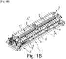
- FIGS. 1 to 7 illustrate, at least in part, a heating mixer 1 for composite products based on thermoplastic material(s), in particular factory or construction site waste mainly containing bituminous membranes.
- This mixer 1 has an elongated structure defining a longitudinal treatment path between an inlet 2 and an outlet 2' and comprises a heated trough 3 in which is mounted at least one screw 4, 4', preferably two parallel and mutually interpenetrating twin screws 4 and 4', forming a dimensional reduction, heating and movement member(s) for the products to be treated introduced at the inlet 2, said or each screw 4, 4' comprising a heated and driven support shaft 5, arranged in the direction of travel DT.
- the thread 4" of the or each screw 4, 4' is an interrupted or discontinuous thread and comprises, over at least a major part of the length of the screw 4, 4' considered, a plurality of first blades 6 in the form of flat and smooth plates, separated from each other axially and radially and all arranged according to a constant screw pitch and with a determined inclination relative to a plane perpendicular to the AV axis of the screw 4, 4' considered.
- the helical thread 4"" of each of the two screws 4 and 4' which rotate in mutually opposite directions of rotation so as to generate a material transport movement from the inlet 2 to the outlet 2' of the trough 3 (in the direction DT), is therefore constituted by a plurality of blades 6 in the form of flat, distinct and separate ring sectors, secured (by welding for example) to the shaft 5 of the screw 4, 4' concerned along a helical line.
- these blades 6 are arranged with a mutual spacing and an individual angular extension such that longitudinal alignments 7 of blades 6 are constituted.
- each first blade 6 has an angular extension around the shaft in question which is less than 180°, advantageously less than 120°, preferably approximately 90°.
- said first blades 6 are configured and arranged on the support shaft 5 in question so as to constitute a limited number of alignments 7 of blades 6 in the direction of the AV axis of the screw 4, 4', which are distributed around the periphery of the support shaft 5 and which define between them clear zones 8 extending along the screw 4, 4' between neighboring alignments 7.
- each of the screws 4, 4' appears substantially like an Archimedes screw with a continuous helical thread, but cut in the direction of the AV axis of the shaft 5 to form rectilinear holes parallel to said AV axis.
- the trough 3 has a double envelope and the shaft 5 is a hollow tube, both of which are traversed by a hot fluid (oil).
- the metal blades 6 are relatively thick (for example 8 to 15 mm) so as to guarantee a certain thermal inertia to heat the bitumen in the mass, while catching and "delumping" the inputs in the form of membranes. (effect “introduction of a hot knife into cold butter”).
- the blades 6 do not offer any grip to the bituminous binder or other.
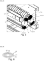
- the or each screw 4, 4' comprises, over at least part of its length, a plurality of second blades 9 in the form of flat plates, separated from each other and all arranged in planes perpendicular to the axis of the screw 4, 4' considered, that each second blade 9 has an angular extension of less than 180°, advantageously less than 120°, preferably approximately 90°, and that said second blades 9 are configured and arranged on the support shaft 5 concerned so as to constitute a limited number of alignments 7' of blades in the direction of the AV axis of the screw 4, 4' and around the shaft 5, cleared zones extending between the neighboring alignments 7' (angularly or circumferentially) along the screw 4, 4'.
- first blades 6 are mounted on the respective shaft 5 with an inclination relative to a plane perpendicular to the AV axis of said shaft, the second blades 9 are shown perpendicular to this AV axis.
- each alignment 7' of second blades 9 extends only over a fraction of the length of the part of the screw 4, 4' comprising them and over a fraction of the periphery of the shaft 5 of the latter and constitutes at least one local group of second blades 9, each group being offset angularly and/or axially relative to each of the other groups and at least one, preferably each group of second blades 9 of a screw 4, 4' coming into interpenetrating engagement, interstitially, with a corresponding group of second blades 9 of the other screw 4', 4.
- the trough 3 may comprise, on at least part of its internal face, located opposite the longitudinal part(s) of the screw 4, 4' comprising second blades 9, fixed counter-blades, located in planes parallel and interstitial with respect to the planes of the second blades 9 and coming into interpenetrating engagement with the second blades 9 during the rotation of the screw 4, 4' considered, each cooperating arrangement of at least two groups of mobile second blades 9 belonging respectively to one of the two screws 4, 4', and possibly of fixed counter-blades, constituting a privileged shear module 11.
- the second blades 9 of the screws 4, 4' are not only interfering and interpenetrating between the two screws 4 and 4', but also with fixed counter-blades installed in the trough 3, for example on a support structure mounted interchangeably in the trough 3 (not shown).
- the areas of the mixer 1 comprising groups of pluralities of second movable blades 9, and possibly fixed counter-blades, constitute, due to the density of interpenetrating blade-forming elements with small air gaps, intense shear modules.
- the mixer 1 may comprise one or more such module(s), where appropriate distributed along the trough 3.
- a (last) shear module is arranged near the outlet of the mixer 1.
- the or each screw is advantageously made up of differentiated longitudinal segments comprising alternately alignments of inclined first blades 6 and alignments of perpendicular second blades 9.
- first and/or second blades 6, 9 are provided, at their outer free edge 9', with at least one added scraping structure 12, projecting radially relative to said edge 9' and elastically deformable at least in one radial direction (see Figures 4 to 6 ).
- the or each deformable added structure 12 consists of a plate 12', or a stack of at least two plates 12', with a substantially elliptical contour and comprising cutouts defining a plurality of concentric elliptical rings 13, connected by material bridges 13' between adjacent rings 13, said structure 12 being mounted on the corresponding blade 6, 9 with an orientation such that the direction of the minor half-axis of the elliptical contour passes through the longitudinal axis AV of the support shaft 5.
- the heating mixer 1 according to the invention may comprise only one screw.
- said mixer 1 comprises two twinned parallel screws 4 and 4' whose respective blades 6, 9 intersect intimately over at least part of their height, preferably a majority part, either in at least one zone of mutual meshing of opposite threads of first blades 6 inclined relative to the axis of the support shaft 5, or in at least one zone of mutual interpenetration of second blades 9 perpendicular to the axis of the support shaft 5, advantageously in both types of zones.
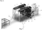
- the invention also has as its object, as shown for example by the figure 7 , an installation 14 for the treatment and recovery of composite products based on thermoplastics, for example waste mainly incorporating bituminous products, in particular bituminous membranes.
- This installation 14 is characterized in that it comprises, as treatment station(s), at least one mixer 1 as described previously, preferably as the first treatment station.
- the installation 14 can comprise two heating mixers 1 as described above, mounted in parallel, supplied with inputs by a conveyor belt 15 (for example transporting pre-cut waste) and each forming the first station of a treatment and recovery route, respectively associated downstream.
- a conveyor belt 15 for example transporting pre-cut waste
- the mixers 1 are installed at a height and their liquid or semi-liquid outputs fall through two superimposed grinding stations 16 each formed by a crusher with opposing rollers (whose air gaps are aligned). Between the two stations 16 can be arranged a device for separating solid macroscopic pollutants in the form of a discharge device (not specifically visible) with a mobile extractor member (by pivoting). Then, the output purified of macroscopic pollutants can be transferred (for example by a delicerator pump 17) into a refiner 18 with a drum mounted eccentrically in a cylindrical enclosure, to then be stored in a tank 19, in the form of a reusable recovered product.
- the invention also relates to a method for controlling a mixer 1 as described above, characterized in that it consists in driving the screw(s) 4, 4' with a control protocol comprising at least two drive phases causing a movement of the materials in the mixer 1 in the direction DT of the treatment path, separated by at least one reverse drive phase, i.e. causing a movement of the treated materials in the direction opposite to the treatment path, the occurrence, duration and number of the reverse drive phases being either predetermined or a function of values provided by sensors for measuring operating parameters, such as for example the drive torque, the composition and/or quality of the treated products, the quantity of materials present in the mixer 1.
Landscapes
- Chemical & Material Sciences (AREA)
- Chemical Kinetics & Catalysis (AREA)
- Engineering & Computer Science (AREA)
- Environmental & Geological Engineering (AREA)
- Mechanical Engineering (AREA)
- Processing Of Solid Wastes (AREA)
- Processing And Handling Of Plastics And Other Materials For Molding In General (AREA)
Applications Claiming Priority (3)
| Application Number | Priority Date | Filing Date | Title |
|---|---|---|---|
| FR2003999A FR3109535B1 (fr) | 2020-04-22 | 2020-04-22 | Mélangeur chauffant pour produit composite |
| PCT/EP2021/058730 WO2021213793A1 (fr) | 2020-04-22 | 2021-04-01 | Melangeur chauffant pour produits composites |
| EP21718057.9A EP4139032B1 (de) | 2020-04-22 | 2021-04-01 | Beheizbarer mischer für verbundwerkstoffe |
Related Parent Applications (1)
| Application Number | Title | Priority Date | Filing Date |
|---|---|---|---|
| EP21718057.9A Division EP4139032B1 (de) | 2020-04-22 | 2021-04-01 | Beheizbarer mischer für verbundwerkstoffe |
Publications (2)
| Publication Number | Publication Date |
|---|---|
| EP4480574A1 true EP4480574A1 (de) | 2024-12-25 |
| EP4480574B1 EP4480574B1 (de) | 2026-02-18 |
Family
ID=71111613
Family Applications (2)
| Application Number | Title | Priority Date | Filing Date |
|---|---|---|---|
| EP24185710.1A Active EP4480574B1 (de) | 2020-04-22 | 2021-04-01 | Heizmischer für verbundprodukte |
| EP21718057.9A Active EP4139032B1 (de) | 2020-04-22 | 2021-04-01 | Beheizbarer mischer für verbundwerkstoffe |
Family Applications After (1)
| Application Number | Title | Priority Date | Filing Date |
|---|---|---|---|
| EP21718057.9A Active EP4139032B1 (de) | 2020-04-22 | 2021-04-01 | Beheizbarer mischer für verbundwerkstoffe |
Country Status (8)
| Country | Link |
|---|---|
| US (1) | US20230201779A1 (de) |
| EP (2) | EP4480574B1 (de) |
| CA (1) | CA3175519A1 (de) |
| ES (1) | ES2992312T3 (de) |
| FR (1) | FR3109535B1 (de) |
| PL (1) | PL4139032T3 (de) |
| PT (1) | PT4139032T (de) |
| WO (1) | WO2021213793A1 (de) |
Families Citing this family (5)
| Publication number | Priority date | Publication date | Assignee | Title |
|---|---|---|---|---|
| FR3125244B1 (fr) | 2021-07-16 | 2025-11-07 | Soprema | Mélangeur chauffant pour produits composites à sortie régulée |
| CN114405318A (zh) * | 2022-01-20 | 2022-04-29 | 广西北投交通养护科技集团有限公司 | 一种智能感应型改性沥青搅拌装置及其使用方法 |
| FR3147116B1 (fr) | 2023-04-03 | 2025-04-04 | Soprema | Procédé et installation de broyage ou de fragmentation de produits bitumineux |
| CN117482838B (zh) * | 2024-01-02 | 2024-03-15 | 水润天府新材料有限公司 | 一种布敦岩沥青改性混合料生产设备及工艺 |
| CN119158483A (zh) * | 2024-11-20 | 2024-12-20 | 福建白鹰新材料科技有限公司 | 一种染整助剂用恒温处理设备及工艺 |
Citations (14)
| Publication number | Priority date | Publication date | Assignee | Title |
|---|---|---|---|---|
| EP0231584A1 (de) | 1986-01-25 | 1987-08-12 | Kubota Limited | Schneckentyp-Trocknungsvorrichtung |
| JPS63209547A (ja) * | 1987-02-25 | 1988-08-31 | Tsukishima Kikai Co Ltd | 処理槽のワイピング装置 |
| DE19531189A1 (de) * | 1995-08-24 | 1997-02-27 | Vakumix Ruehr Und Homogenisier | Abstreifvorrichtung |
| EP1123182A1 (de) | 1998-09-22 | 2001-08-16 | Performance Roof Systems S.A. | Verfahren zur wiedergewinnung einer membran und extrusionsmaschine zur durchführung des verfahrens |
| US20050263625A1 (en) | 2002-06-28 | 2005-12-01 | Nino Macaluso | Unit and method for recycling a bituminous membrane |
| WO2007134541A1 (fr) * | 2006-05-22 | 2007-11-29 | Andy Mingfen Tung | Mélangeur pour toilettes écologiques et appareil de traitement associé |
| WO2008103035A1 (en) | 2007-02-19 | 2008-08-28 | Esha Group B.V. | Apparatus and method for recycling bituminous roofing waste |
| EP2015019A1 (de) * | 2007-06-22 | 2009-01-14 | Goudsche MachineFabriek B.V. | Wärmetauschervorrichtung mit Radialmischung |
| WO2009090546A2 (en) | 2008-01-18 | 2009-07-23 | Euroline S.R.L. | Machine and method for shredding portions of bituminous material into recyclable granules |
| DE102008045652A1 (de) * | 2008-09-03 | 2010-05-20 | Alco-Food-Machines Gmbh & Co. Kg | Lebensmittelmischanlage zur Verarbeitung von Lebensmitteln |
| US20120081992A1 (en) * | 2010-10-05 | 2012-04-05 | Whirlpool Corporation | Stand mixer wiping beater |
| EP3330653A1 (de) * | 2015-07-29 | 2018-06-06 | Shin Nichinan CO., LTD | Vorrichtung zum heizen oder kühlen von ausgangsmaterial |
| FR3060417A1 (fr) * | 2016-12-15 | 2018-06-22 | Lab Sa | Reacteur de reactivation de solides |
| US20190145065A1 (en) * | 2016-05-10 | 2019-05-16 | Colas | Apparatus for in-place recycling of materials forming part of a roadway pavement, and crusher for milling debris from a roadway pavement |
-
2020
- 2020-04-22 FR FR2003999A patent/FR3109535B1/fr active Active
-
2021
- 2021-04-01 EP EP24185710.1A patent/EP4480574B1/de active Active
- 2021-04-01 WO PCT/EP2021/058730 patent/WO2021213793A1/fr not_active Ceased
- 2021-04-01 ES ES21718057T patent/ES2992312T3/es active Active
- 2021-04-01 PT PT217180579T patent/PT4139032T/pt unknown
- 2021-04-01 EP EP21718057.9A patent/EP4139032B1/de active Active
- 2021-04-01 PL PL21718057.9T patent/PL4139032T3/pl unknown
- 2021-04-01 US US17/920,358 patent/US20230201779A1/en not_active Abandoned
- 2021-04-01 CA CA3175519A patent/CA3175519A1/fr active Pending
Patent Citations (14)
| Publication number | Priority date | Publication date | Assignee | Title |
|---|---|---|---|---|
| EP0231584A1 (de) | 1986-01-25 | 1987-08-12 | Kubota Limited | Schneckentyp-Trocknungsvorrichtung |
| JPS63209547A (ja) * | 1987-02-25 | 1988-08-31 | Tsukishima Kikai Co Ltd | 処理槽のワイピング装置 |
| DE19531189A1 (de) * | 1995-08-24 | 1997-02-27 | Vakumix Ruehr Und Homogenisier | Abstreifvorrichtung |
| EP1123182A1 (de) | 1998-09-22 | 2001-08-16 | Performance Roof Systems S.A. | Verfahren zur wiedergewinnung einer membran und extrusionsmaschine zur durchführung des verfahrens |
| US20050263625A1 (en) | 2002-06-28 | 2005-12-01 | Nino Macaluso | Unit and method for recycling a bituminous membrane |
| WO2007134541A1 (fr) * | 2006-05-22 | 2007-11-29 | Andy Mingfen Tung | Mélangeur pour toilettes écologiques et appareil de traitement associé |
| WO2008103035A1 (en) | 2007-02-19 | 2008-08-28 | Esha Group B.V. | Apparatus and method for recycling bituminous roofing waste |
| EP2015019A1 (de) * | 2007-06-22 | 2009-01-14 | Goudsche MachineFabriek B.V. | Wärmetauschervorrichtung mit Radialmischung |
| WO2009090546A2 (en) | 2008-01-18 | 2009-07-23 | Euroline S.R.L. | Machine and method for shredding portions of bituminous material into recyclable granules |
| DE102008045652A1 (de) * | 2008-09-03 | 2010-05-20 | Alco-Food-Machines Gmbh & Co. Kg | Lebensmittelmischanlage zur Verarbeitung von Lebensmitteln |
| US20120081992A1 (en) * | 2010-10-05 | 2012-04-05 | Whirlpool Corporation | Stand mixer wiping beater |
| EP3330653A1 (de) * | 2015-07-29 | 2018-06-06 | Shin Nichinan CO., LTD | Vorrichtung zum heizen oder kühlen von ausgangsmaterial |
| US20190145065A1 (en) * | 2016-05-10 | 2019-05-16 | Colas | Apparatus for in-place recycling of materials forming part of a roadway pavement, and crusher for milling debris from a roadway pavement |
| FR3060417A1 (fr) * | 2016-12-15 | 2018-06-22 | Lab Sa | Reacteur de reactivation de solides |
Also Published As
| Publication number | Publication date |
|---|---|
| PT4139032T (pt) | 2024-10-22 |
| ES2992312T3 (es) | 2024-12-11 |
| WO2021213793A1 (fr) | 2021-10-28 |
| PL4139032T3 (pl) | 2025-02-17 |
| FR3109535B1 (fr) | 2023-04-14 |
| US20230201779A1 (en) | 2023-06-29 |
| CA3175519A1 (fr) | 2021-10-28 |
| FR3109535A1 (fr) | 2021-10-29 |
| EP4480574B1 (de) | 2026-02-18 |
| EP4139032B1 (de) | 2024-07-24 |
| EP4139032A1 (de) | 2023-03-01 |
Similar Documents
| Publication | Publication Date | Title |
|---|---|---|
| EP4480574B1 (de) | Heizmischer für verbundprodukte | |
| EP4139105B1 (de) | Anlage und verfahren zur behandlung von verbundwerkstoffen auf basis von thermoplastischen kunststoffen | |
| EP2473294B1 (de) | Recycling-verfahren und -anlage für gipsabfall | |
| EP1534434A1 (de) | Verfahren und einheit zum recyceln einer bitumenmembran | |
| JPH02272108A (ja) | 溝内を流れる液体からレーキ物質および/または篩い物質を除去する装置 | |
| EP4370299B1 (de) | Beheizbarer mischer für verbundwerkstoffe mit gesteuertem ausgang | |
| WO1995008393A1 (en) | Glass shearing apparatus and method | |
| CA3175511A1 (fr) | Raffineur, installation et procede pour le traitement de produits composites | |
| US20260115969A1 (en) | Splashguard device for a wheeled vehicle and assembly comprising such a device | |
| EP1074303A1 (de) | Trommel für einen Abfallbehandlungsapparat und entsprechender Apparat | |
| FR2460551A1 (fr) | Procede et dispositif pour la fragmentation de batteries | |
| CN211646226U (zh) | 一种市政工程道路养护设备 | |
| KR20160130375A (ko) | 잘게 잘린 플라스틱으로부터 불순물을 제거하기 위한 장치 | |
| WO2024208606A1 (fr) | Procédé et installation de broyage ou de fragmentation de produits bitumineux | |
| CN210585317U (zh) | 一种建筑垃圾用的破碎装置 | |
| RU2188890C1 (ru) | Способ удаления снежно-ледяной массы, собираемой с территории мегаполиса, и устройство для осуществления этого способа | |
| RU2583679C1 (ru) | Способ принудительного, интенсивного таяния снега, засорённого твердыми включениями и бытовым мусором | |
| EP1103360A1 (de) | Sägevorrichtung für Naturstein | |
| FR3032133A1 (fr) | Machine et installation de purification des granulats issus du beton | |
| EP4271523A1 (de) | Messerschleifmaschine für gipsrecycling | |
| TWM273394U (en) | Lubrication pack dedicated for paper shredder | |
| UA56781A (uk) | Спосіб відновлення покрівель з бітумвмісних матеріалів | |
| JPH04161254A (ja) | 合成樹脂用衝撃破砕機 |
Legal Events
| Date | Code | Title | Description |
|---|---|---|---|
| PUAI | Public reference made under article 153(3) epc to a published international application that has entered the european phase |
Free format text: ORIGINAL CODE: 0009012 |
|
| STAA | Information on the status of an ep patent application or granted ep patent |
Free format text: STATUS: THE APPLICATION HAS BEEN PUBLISHED |
|
| AC | Divisional application: reference to earlier application |
Ref document number: 4139032 Country of ref document: EP Kind code of ref document: P |
|
| AK | Designated contracting states |
Kind code of ref document: A1 Designated state(s): AL AT BE BG CH CY CZ DE DK EE ES FI FR GB GR HR HU IE IS IT LI LT LU LV MC MK MT NL NO PL PT RO RS SE SI SK SM TR |
|
| STAA | Information on the status of an ep patent application or granted ep patent |
Free format text: STATUS: REQUEST FOR EXAMINATION WAS MADE |
|
| 17P | Request for examination filed |
Effective date: 20250616 |
|
| P01 | Opt-out of the competence of the unified patent court (upc) registered |
Free format text: CASE NUMBER: APP_29333/2025 Effective date: 20250619 |
|
| GRAP | Despatch of communication of intention to grant a patent |
Free format text: ORIGINAL CODE: EPIDOSNIGR1 |
|
| STAA | Information on the status of an ep patent application or granted ep patent |
Free format text: STATUS: GRANT OF PATENT IS INTENDED |
|
| RIC1 | Information provided on ipc code assigned before grant |
Ipc: B01F 27/091 20220101AFI20250901BHEP Ipc: B01F 27/702 20220101ALI20250901BHEP Ipc: B01F 27/723 20220101ALI20250901BHEP Ipc: B01F 35/92 20220101ALI20250901BHEP Ipc: B01F 35/95 20220101ALI20250901BHEP Ipc: B29B 17/04 20060101ALI20250901BHEP Ipc: B29K 95/00 20060101ALN20250901BHEP Ipc: B29L 31/10 20060101ALN20250901BHEP |
|
| INTG | Intention to grant announced |
Effective date: 20250918 |
|
| GRAS | Grant fee paid |
Free format text: ORIGINAL CODE: EPIDOSNIGR3 |
|
| GRAA | (expected) grant |
Free format text: ORIGINAL CODE: 0009210 |
|
| STAA | Information on the status of an ep patent application or granted ep patent |
Free format text: STATUS: THE PATENT HAS BEEN GRANTED |
|
| AC | Divisional application: reference to earlier application |
Ref document number: 4139032 Country of ref document: EP Kind code of ref document: P |
|
| AK | Designated contracting states |
Kind code of ref document: B1 Designated state(s): AL AT BE BG CH CY CZ DE DK EE ES FI FR GB GR HR HU IE IS IT LI LT LU LV MC MK MT NL NO PL PT RO RS SE SI SK SM TR |
|
| REG | Reference to a national code |
Ref country code: CH Ref legal event code: F10 Free format text: ST27 STATUS EVENT CODE: U-0-0-F10-F00 (AS PROVIDED BY THE NATIONAL OFFICE) Effective date: 20260218 Ref country code: GB Ref legal event code: FG4D Free format text: NOT ENGLISH |
|
| REG | Reference to a national code |
Ref country code: IE Ref legal event code: FG4D Free format text: LANGUAGE OF EP DOCUMENT: FRENCH |
|
| REG | Reference to a national code |
Ref country code: DE Ref legal event code: R096 Ref document number: 602021048507 Country of ref document: DE |