EP4480608A2 - Verfahren zur herstellung von dauermagneten - Google Patents
Verfahren zur herstellung von dauermagneten Download PDFInfo
- Publication number
- EP4480608A2 EP4480608A2 EP24205665.3A EP24205665A EP4480608A2 EP 4480608 A2 EP4480608 A2 EP 4480608A2 EP 24205665 A EP24205665 A EP 24205665A EP 4480608 A2 EP4480608 A2 EP 4480608A2
- Authority
- EP
- European Patent Office
- Prior art keywords
- metal alloy
- container
- permanent magnet
- alloy powder
- tube
- Prior art date
- Legal status (The legal status is an assumption and is not a legal conclusion. Google has not performed a legal analysis and makes no representation as to the accuracy of the status listed.)
- Pending
Links
Images




Classifications
-
- H—ELECTRICITY
- H01—ELECTRIC ELEMENTS
- H01F—MAGNETS; INDUCTANCES; TRANSFORMERS; SELECTION OF MATERIALS FOR THEIR MAGNETIC PROPERTIES
- H01F1/00—Magnets or magnetic bodies characterised by the magnetic materials therefor; Selection of materials for their magnetic properties
- H01F1/01—Magnets or magnetic bodies characterised by the magnetic materials therefor; Selection of materials for their magnetic properties of inorganic materials
- H01F1/03—Magnets or magnetic bodies characterised by the magnetic materials therefor; Selection of materials for their magnetic properties of inorganic materials characterised by their coercivity
- H01F1/032—Magnets or magnetic bodies characterised by the magnetic materials therefor; Selection of materials for their magnetic properties of inorganic materials characterised by their coercivity of hard-magnetic materials
- H01F1/04—Magnets or magnetic bodies characterised by the magnetic materials therefor; Selection of materials for their magnetic properties of inorganic materials characterised by their coercivity of hard-magnetic materials metals or alloys
- H01F1/047—Alloys characterised by their composition
- H01F1/053—Alloys characterised by their composition containing rare earth metals
- H01F1/055—Alloys characterised by their composition containing rare earth metals and magnetic transition metals, e.g. SmCo5
- H01F1/057—Alloys characterised by their composition containing rare earth metals and magnetic transition metals, e.g. SmCo5 and IIIa elements, e.g. Nd2Fe14B
- H01F1/0571—Alloys characterised by their composition containing rare earth metals and magnetic transition metals, e.g. SmCo5 and IIIa elements, e.g. Nd2Fe14B in the form of particles, e.g. rapid quenched powders or ribbon flakes
- H01F1/0575—Alloys characterised by their composition containing rare earth metals and magnetic transition metals, e.g. SmCo5 and IIIa elements, e.g. Nd2Fe14B in the form of particles, e.g. rapid quenched powders or ribbon flakes pressed, sintered or bonded together
- H01F1/0577—Alloys characterised by their composition containing rare earth metals and magnetic transition metals, e.g. SmCo5 and IIIa elements, e.g. Nd2Fe14B in the form of particles, e.g. rapid quenched powders or ribbon flakes pressed, sintered or bonded together sintered
-
- B—PERFORMING OPERATIONS; TRANSPORTING
- B22—CASTING; POWDER METALLURGY
- B22F—WORKING METALLIC POWDER; MANUFACTURE OF ARTICLES FROM METALLIC POWDER; MAKING METALLIC POWDER; APPARATUS OR DEVICES SPECIALLY ADAPTED FOR METALLIC POWDER
- B22F3/00—Manufacture of workpieces or articles from metallic powder characterised by the manner of compacting or sintering; Apparatus specially adapted therefor ; Presses and furnaces
- B22F3/12—Both compacting and sintering
-
- B—PERFORMING OPERATIONS; TRANSPORTING
- B22—CASTING; POWDER METALLURGY
- B22F—WORKING METALLIC POWDER; MANUFACTURE OF ARTICLES FROM METALLIC POWDER; MAKING METALLIC POWDER; APPARATUS OR DEVICES SPECIALLY ADAPTED FOR METALLIC POWDER
- B22F3/00—Manufacture of workpieces or articles from metallic powder characterised by the manner of compacting or sintering; Apparatus specially adapted therefor ; Presses and furnaces
- B22F3/12—Both compacting and sintering
- B22F3/16—Both compacting and sintering in successive or repeated steps
-
- B—PERFORMING OPERATIONS; TRANSPORTING
- B22—CASTING; POWDER METALLURGY
- B22F—WORKING METALLIC POWDER; MANUFACTURE OF ARTICLES FROM METALLIC POWDER; MAKING METALLIC POWDER; APPARATUS OR DEVICES SPECIALLY ADAPTED FOR METALLIC POWDER
- B22F3/00—Manufacture of workpieces or articles from metallic powder characterised by the manner of compacting or sintering; Apparatus specially adapted therefor ; Presses and furnaces
- B22F3/17—Manufacture of workpieces or articles from metallic powder characterised by the manner of compacting or sintering; Apparatus specially adapted therefor ; Presses and furnaces by forging
-
- B—PERFORMING OPERATIONS; TRANSPORTING
- B22—CASTING; POWDER METALLURGY
- B22F—WORKING METALLIC POWDER; MANUFACTURE OF ARTICLES FROM METALLIC POWDER; MAKING METALLIC POWDER; APPARATUS OR DEVICES SPECIALLY ADAPTED FOR METALLIC POWDER
- B22F3/00—Manufacture of workpieces or articles from metallic powder characterised by the manner of compacting or sintering; Apparatus specially adapted therefor ; Presses and furnaces
- B22F3/24—After-treatment of workpieces or articles
-
- B—PERFORMING OPERATIONS; TRANSPORTING
- B22—CASTING; POWDER METALLURGY
- B22F—WORKING METALLIC POWDER; MANUFACTURE OF ARTICLES FROM METALLIC POWDER; MAKING METALLIC POWDER; APPARATUS OR DEVICES SPECIALLY ADAPTED FOR METALLIC POWDER
- B22F5/00—Manufacture of workpieces or articles from metallic powder characterised by the special shape of the product
- B22F5/12—Manufacture of workpieces or articles from metallic powder characterised by the special shape of the product of wires
-
- C—CHEMISTRY; METALLURGY
- C22—METALLURGY; FERROUS OR NON-FERROUS ALLOYS; TREATMENT OF ALLOYS OR NON-FERROUS METALS
- C22C—ALLOYS
- C22C1/00—Making non-ferrous alloys
- C22C1/02—Making non-ferrous alloys by melting
-
- H—ELECTRICITY
- H01—ELECTRIC ELEMENTS
- H01F—MAGNETS; INDUCTANCES; TRANSFORMERS; SELECTION OF MATERIALS FOR THEIR MAGNETIC PROPERTIES
- H01F41/00—Apparatus or processes specially adapted for manufacturing or assembling magnets, inductances or transformers; Apparatus or processes specially adapted for manufacturing materials characterised by their magnetic properties
- H01F41/02—Apparatus or processes specially adapted for manufacturing or assembling magnets, inductances or transformers; Apparatus or processes specially adapted for manufacturing materials characterised by their magnetic properties for manufacturing cores, coils, or magnets
- H01F41/0253—Apparatus or processes specially adapted for manufacturing or assembling magnets, inductances or transformers; Apparatus or processes specially adapted for manufacturing materials characterised by their magnetic properties for manufacturing cores, coils, or magnets for manufacturing permanent magnets
- H01F41/0266—Moulding; Pressing
-
- H—ELECTRICITY
- H01—ELECTRIC ELEMENTS
- H01F—MAGNETS; INDUCTANCES; TRANSFORMERS; SELECTION OF MATERIALS FOR THEIR MAGNETIC PROPERTIES
- H01F41/00—Apparatus or processes specially adapted for manufacturing or assembling magnets, inductances or transformers; Apparatus or processes specially adapted for manufacturing materials characterised by their magnetic properties
- H01F41/02—Apparatus or processes specially adapted for manufacturing or assembling magnets, inductances or transformers; Apparatus or processes specially adapted for manufacturing materials characterised by their magnetic properties for manufacturing cores, coils, or magnets
- H01F41/0253—Apparatus or processes specially adapted for manufacturing or assembling magnets, inductances or transformers; Apparatus or processes specially adapted for manufacturing materials characterised by their magnetic properties for manufacturing cores, coils, or magnets for manufacturing permanent magnets
- H01F41/0273—Imparting anisotropy
-
- B—PERFORMING OPERATIONS; TRANSPORTING
- B22—CASTING; POWDER METALLURGY
- B22F—WORKING METALLIC POWDER; MANUFACTURE OF ARTICLES FROM METALLIC POWDER; MAKING METALLIC POWDER; APPARATUS OR DEVICES SPECIALLY ADAPTED FOR METALLIC POWDER
- B22F3/00—Manufacture of workpieces or articles from metallic powder characterised by the manner of compacting or sintering; Apparatus specially adapted therefor ; Presses and furnaces
- B22F3/24—After-treatment of workpieces or articles
- B22F2003/245—Making recesses, grooves etc on the surface by removing material
-
- B—PERFORMING OPERATIONS; TRANSPORTING
- B22—CASTING; POWDER METALLURGY
- B22F—WORKING METALLIC POWDER; MANUFACTURE OF ARTICLES FROM METALLIC POWDER; MAKING METALLIC POWDER; APPARATUS OR DEVICES SPECIALLY ADAPTED FOR METALLIC POWDER
- B22F3/00—Manufacture of workpieces or articles from metallic powder characterised by the manner of compacting or sintering; Apparatus specially adapted therefor ; Presses and furnaces
- B22F3/24—After-treatment of workpieces or articles
- B22F2003/247—Removing material: carving, cleaning, grinding, hobbing, honing, lapping, polishing, milling, shaving, skiving, turning the surface
-
- B—PERFORMING OPERATIONS; TRANSPORTING
- B22—CASTING; POWDER METALLURGY
- B22F—WORKING METALLIC POWDER; MANUFACTURE OF ARTICLES FROM METALLIC POWDER; MAKING METALLIC POWDER; APPARATUS OR DEVICES SPECIALLY ADAPTED FOR METALLIC POWDER
- B22F3/00—Manufacture of workpieces or articles from metallic powder characterised by the manner of compacting or sintering; Apparatus specially adapted therefor ; Presses and furnaces
- B22F3/24—After-treatment of workpieces or articles
- B22F2003/248—Thermal after-treatment
-
- B—PERFORMING OPERATIONS; TRANSPORTING
- B22—CASTING; POWDER METALLURGY
- B22F—WORKING METALLIC POWDER; MANUFACTURE OF ARTICLES FROM METALLIC POWDER; MAKING METALLIC POWDER; APPARATUS OR DEVICES SPECIALLY ADAPTED FOR METALLIC POWDER
- B22F2202/00—Treatment under specific physical conditions
- B22F2202/05—Use of magnetic field
-
- B—PERFORMING OPERATIONS; TRANSPORTING
- B22—CASTING; POWDER METALLURGY
- B22F—WORKING METALLIC POWDER; MANUFACTURE OF ARTICLES FROM METALLIC POWDER; MAKING METALLIC POWDER; APPARATUS OR DEVICES SPECIALLY ADAPTED FOR METALLIC POWDER
- B22F2998/00—Supplementary information concerning processes or compositions relating to powder metallurgy
- B22F2998/10—Processes characterised by the sequence of their steps
-
- B—PERFORMING OPERATIONS; TRANSPORTING
- B22—CASTING; POWDER METALLURGY
- B22F—WORKING METALLIC POWDER; MANUFACTURE OF ARTICLES FROM METALLIC POWDER; MAKING METALLIC POWDER; APPARATUS OR DEVICES SPECIALLY ADAPTED FOR METALLIC POWDER
- B22F2999/00—Aspects linked to processes or compositions used in powder metallurgy
-
- B—PERFORMING OPERATIONS; TRANSPORTING
- B22—CASTING; POWDER METALLURGY
- B22F—WORKING METALLIC POWDER; MANUFACTURE OF ARTICLES FROM METALLIC POWDER; MAKING METALLIC POWDER; APPARATUS OR DEVICES SPECIALLY ADAPTED FOR METALLIC POWDER
- B22F9/00—Making metallic powder or suspensions thereof
- B22F9/02—Making metallic powder or suspensions thereof using physical processes
- B22F9/04—Making metallic powder or suspensions thereof using physical processes starting from solid material, e.g. by crushing, grinding or milling
-
- B—PERFORMING OPERATIONS; TRANSPORTING
- B22—CASTING; POWDER METALLURGY
- B22F—WORKING METALLIC POWDER; MANUFACTURE OF ARTICLES FROM METALLIC POWDER; MAKING METALLIC POWDER; APPARATUS OR DEVICES SPECIALLY ADAPTED FOR METALLIC POWDER
- B22F9/00—Making metallic powder or suspensions thereof
- B22F9/02—Making metallic powder or suspensions thereof using physical processes
- B22F9/06—Making metallic powder or suspensions thereof using physical processes starting from liquid material
-
- C—CHEMISTRY; METALLURGY
- C22—METALLURGY; FERROUS OR NON-FERROUS ALLOYS; TREATMENT OF ALLOYS OR NON-FERROUS METALS
- C22C—ALLOYS
- C22C2202/00—Physical properties
- C22C2202/02—Magnetic
-
- H—ELECTRICITY
- H01—ELECTRIC ELEMENTS
- H01F—MAGNETS; INDUCTANCES; TRANSFORMERS; SELECTION OF MATERIALS FOR THEIR MAGNETIC PROPERTIES
- H01F13/00—Apparatus or processes for magnetising or demagnetising
- H01F13/003—Methods and devices for magnetising permanent magnets
-
- H—ELECTRICITY
- H01—ELECTRIC ELEMENTS
- H01F—MAGNETS; INDUCTANCES; TRANSFORMERS; SELECTION OF MATERIALS FOR THEIR MAGNETIC PROPERTIES
- H01F7/00—Magnets
- H01F7/02—Permanent magnets [PM]
- H01F7/0231—Magnetic circuits with PM for power or force generation
- H01F7/0242—Magnetic drives, magnetic coupling devices
Definitions
- the present disclosure generally relates to permanent magnets; more specifically, the present disclosure relates to a method of manufacturing permanent magnets comprising a powdered metal alloy contained within an enclosed volume of a container of any desired cross sectional shape.
- Permanent magnets with high energy products such as neodymium-iron-boron magnets, are conventionally produced with a modified powdered metallurgical process in simple geometrical forms like discs, cuboids and parallelepiped.
- a conventional process of manufacturing an exemplary combination of metals, neodymium-iron-boron, is shown and described with reference to FIG. 1 .
- powdered metals are created. To do this, the appropriate amounts of neodymium, iron, and boron are combined and heated to the melting point under vacuum. As used herein, "alloy” is used to refer to the resulting substance in both liquid and solid states. The vacuum prevents any chemical reaction between air and the melting materials that might contaminate the final metal alloy. Once the metal alloy has cooled and solidified, it is broken up and crushed into small pieces, which are ground into a fine powder creating a powdered metal alloy.
- the powdered metal alloy is pressed.
- the powder is placed in a die that has the shape of the finished magnet.
- a magnetic field is applied to the powder to line up the powder particles. While the magnetic force is being applied, the powder is pressed from the top and bottom with hydraulic or mechanical rams to compress it to within about 0.125 inches (0.32 cm) of its final intended thickness. Typical pressures are about 10,000 psi to 15,000 psi (70 MPa to 100 MPa).
- Some shapes are made by placing the powder in a flexible, air-tight, evacuated container and pressing it into shape with liquid or gas pressure. This is known as isostatic compaction.
- the powdered metal alloy is heated.
- the metal alloy is removed from the die and placed in an oven for sintering, which fuses the powder into a solid piece.
- the process usually consists of three stages. In the first stage, the alloy is heated at a low temperature to slowly drive off any moisture or other contaminants that may have become entrapped during the pressing process. In the second stage, the temperature is raised to about 70-90% of the melting point of the metal alloy and held there for a period of several hours or several days to allow the small particles to fuse together. Finally, the alloy is slowly cooled down in controlled, step-by-step temperature increments.
- the sintered metal alloy then undergoes a second controlled heating and cooling process known as annealing. This process removes any residual stresses within the alloy and strengthens it.
- the annealed metal alloy is very close to the finished shape and required dimensions.
- a final machining process removes any excess material and produces a smooth surface.
- the alloy is then given a protective coating to seal the surfaces.
- the metal alloy is magnetized. Up to this point, the metal alloy is just a piece of compressed and fused metal. Even though it was subjected to a magnetic force during pressing, that force did not magnetize the alloy, it simply lined up the loose powder particles. To turn it into a magnet, the alloy is placed between the poles of a powerful electromagnet and oriented in the desired direction of magnetization. The electromagnet is then energized for a period of time. The magnetic force aligns the groups of atoms, or magnetic domains, within the material to transform the alloy into a strong permanent magnet.
- the invention is a novel and enabling process for economical production of permanent magnets, having the potential to revolutionize permanent magnet manufacturing; lower cost product, lower cost and safer assembly of magnet-based products, enabler for the application of future permanent magnet materials and enabling new magnet-based products having potential for high-impact solutions for energy, medical, transportation and environmental industries.
- the novel Permanent Magnet (PM) manufacturing technology of the invention termed PM-Wire, overcomes many inherent issues with conventional magnet production methods.
- the process of the invention enables mass-produced, cost-effective PM products, which are more robust, easily assembled into products and enables new "wire like" shapes and significantly increases energy density.
- the novel process comprises a "powder-in-tube” process that is continuous and may utilize drawing, packing and shaping processes, allows for mass production of permanent magnets of any desired shape or cross section, produces permanent magnets continuously that may be cut to any length, and may, in an embodiment, result in magnets with a desired magnetization direction.
- a method manufacturing a permanent magnet comprises heating a plurality of magnetic metals to their melting point under vacuum to create a metal alloy, allowing the metal alloy to cool and solidify and then grounding the metal alloy into a fine powder.
- the plurality of magnetic metals may be neodymium, iron and boron.
- the metal alloy powder is then placed in a tube or other shaped container.
- the tube or other shaped container may comprise a non-magnetic metal.
- a magnetic field is applied to the metal alloy while the metal alloy and tube it is contained in are compressed.
- the process of compressing the metal alloy and tube may comprise swaging the metal alloy and tube or other shaped container.
- the metal alloy and tube are then sintered and cooled. After cooling, the metal alloy is magnetized. Magnetization may comprise placing the metal alloy between two poles of an electromagnet and energizing the electromagnet.
- a permanent magnet is prepared by the above process.
- FIGS. 2 through 8 A detailed description of the embodiments for a method of manufacturing permanent magnets will now be presented with reference to FIGS. 2 through 8 .
- FIGS. 2 through 8 A detailed description of the embodiments for a method of manufacturing permanent magnets will now be presented with reference to FIGS. 2 through 8 .
- FIGS. 2 through 8 A detailed description of the embodiments for a method of manufacturing permanent magnets will now be presented with reference to FIGS. 2 through 8 .
- tube includes within its definition any desired shape enclosing an interior volume.
- PM Wire is used to refer to any permanent magnet shape or configuration produced by the inventive method, and is therefore not limited only to “wire” constructs or shapes.
- Embodiments of the manufacturing process disclosed herein overcome some of the inherent issues with the conventional manufacturing method and, in particular, enable cost effective manufacturing of complex magnetic arrays, such as Halbach arrays.
- Embodiments of the manufacturing process enable mass production of permanent magnets that are more mechanically robust than conventional permanent magnets and more easily assembled into complex arrays. In some cases, permanent magnets created can be bent into arcs.
- FIG. 2 An exemplary embodiment of the inventive process for manufacturing a permanent magnet is shown and described with reference to FIG. 2 .
- An exemplary list of magnetic metals that may be used in the apparatus and method are neodymium, iron, cobalt, boron, gadolinium, dysprosium and alloys such as steel that contain ferromagnetic metals, alone in any combination.. These identified magnetic metals listed of should not be taken as limiting. Any magnetic material can be used in the process of the invention to produce permanent magnets of a desired magnetic material or combination of materials. In particular, various novel magnetic materials, currently under development, which are not based on rare-earth materials, can be used.
- step 100 powdered metals are created.
- the appropriate amounts of magnetic materials such as, for example and not by way of limitation, neodymium, iron and boron are combined and heated to their melting point under vacuum. The vacuum prevents any chemical reaction between air and the melting materials that might contaminate the final metal alloy.
- the metal alloy Once the metal alloy has cooled and solidified, it is broken up and crushed into small pieces, which are ground into a fine powder creating a powdered metal alloy.
- a second step 101 pressure is applied to the powdered metal alloy.
- the powder is inserted into a tube or other-shaped container of a non-magnetic metal depicted as 001 in Fig. 6C .
- the non-magnetic metal tube or other-shaped container may be, for example, stainless steel or titanium.
- the material has to be non-magnetic to allow unhampered penetration of magnetic flux through the tube or other shaped container wall.
- swaging is used to compress the powder.
- the resulting shape can vary depending on the swaging process. Exemplary resulting tube shapes include cylindrical, rectangular prism, square prism, and pie-shaped.
- FIG. 3A and 3B Cross-sectional and perspective views of a cylindrical tube are shown in FIG. 3A and 3B , respectively.
- Cross-sectional and perspective views of a rectangular prism-shaped tube are shown in FIG. 4A and 4B , respectively.
- Cross-sectional and perspective views of a square prism-shaped tube are shown in FIG. 5A and 5B , respectively.
- the outer dimensions of the original tube or other-shaped container can vary depending on the desired diameter of the resulting tubes after swaging.
- the length of the tube can also vary and can be significant.
- a resulting tube may be one meter long and have a diameter or cross-sectional length of two centimeters or more. Even tubes with very small diameter that can be described as wires are producible by the process of the invention.
- the enclosed volume is described herein as a tube for convenience, the container of the invention may take any desired shape as long as it has an interior volume able to contain the powdered metal alloy as described herein.
- a third step 102 once compressed, the powdered metal alloy is heated.
- the powdered metal alloy still in its tube, is sintered with the appropriate temperature profile.
- the alloy is then slowly cooled down.
- a bonding agent such as a chemical bonding agent, epoxy, or the like may be mixed with the powdered metal alloy.
- the bonding agent is then cured, producing a permanent magnet of a desired shape that is ready for final finishing.
- the alloy still in its tube or other-shaped container ( Fig. 2 ), is magnetized 103.
- the magnetization direction will be chosen to be perpendicular to the tube axis.
- the magnetization direction may also be along the tube axis.
- Halbach arrays comprising permanent magnets produced by the processes and methods described herein.
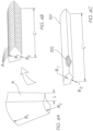
- FIG. 6A, 6B, 6C , and 7 an application of the inventive method for producing a permanent magnet which results in a permanent magnet wire (PM-Wire) of pie-shaped cross section is depicted.
- PM-Wire permanent magnet wire
- FIG. 7 the example PM Wire cross section depicted in these figures is one of many cross sections of the PM Wire that may be produced by the process of the invention and that numerous other cross sectional shapes are within the scope of the invention.
- the exemplary dual Halbach array application depicted in Fig. 7 is but one of many applications of the process and permanent magnet(s) that may be produced by the process.
- the exemplary application depicted in Fig. 7 is a dual-Halbach array electric motor that may be used in electric engines for aircraft propulsion.
- pie-shaped PM Wire produced by the process of the invention is the enablement of smaller diameter electric engines producing magnetic field strengths of up to 2.0 tesla, or greater. This is especially true when stator 006 is a double-helix or direct double helix conductor configuration as described in U.S. patents 7,889,042 , 7,990,247 , or 8,424,193 , each of which are incorporated herein by reference in their entirety.
- a permanent magnet A produced by traditional means is shown for reference in Fig.
- a pie-shaped cross section PM Wire produced by the continuous process may be defined as having an inner radius R2' and outer radius R1' of the invention is depicted in FIG. 6C .
- the outer radius R1' of the PM Wire may be, for example much less than the outer diameter R1 of the traditional permanent magnet, allowing for a smaller diameter engine.
- the length L' of the PM Wire produced by the process of the invention may much longer than the length L of a traditional permanent magnet A because the process of the invention is continuous, allowing less expensive and much easier construction of a longer engine comprising, for example, dual coaxial Halbach arrays (or a single Halbach array, if desired) because the for assembling together a plurality of pie-shaped permanent magnets along the axial direction, as would be required to construct a motor of length L' using traditional pie-shaped permanent magnets as shown in Fig. 6B , is eliminated.
- the pie-shaped PM Wire segments may be assembled into place and welded together using known fabrication techniques such as electron beam welding. If the Curie temperature can be exceeded in the welding process the PM Wires must be glued together. The result is lower cost and higher speed fabrication and assembly.
- the sintered, magnetized powdered metal alloy 002 is contained with the pie-shaped tube 001 as shown in Fig. 6C .
- an outer Halbach array comprises a plurality of PM Wire segments 003
- an inner Halbach array comprises a plurality of pie shaped PM Wire segments 004.
- the two Halbach arrays, the outer shell, stator 006 and engine shaft 005 are coaxial with the longitudinal axis of the engine.
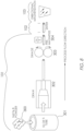
- step 101 comprises placing the powdered metal alloy, such as, for example, NdFeB powder 300, into a tube of any desired cross sectional shape or length 301.
- the tube with powdered metal alloy inside is then drawn through a die 302 and subsequently swaged 303 and pre-magnetized 304.
- step 102 the powder-in-tube is sintered 102 and magnetized with powerful electromagnets 103, producing a permanent magnet of a desired cross sectional shape and desired magnetization.
Landscapes
- Engineering & Computer Science (AREA)
- Manufacturing & Machinery (AREA)
- Mechanical Engineering (AREA)
- Power Engineering (AREA)
- Chemical & Material Sciences (AREA)
- Inorganic Chemistry (AREA)
- Crystallography & Structural Chemistry (AREA)
- Metallurgy (AREA)
- Organic Chemistry (AREA)
- Materials Engineering (AREA)
- Manufacturing Cores, Coils, And Magnets (AREA)
- Powder Metallurgy (AREA)
- Hard Magnetic Materials (AREA)
Applications Claiming Priority (4)
| Application Number | Priority Date | Filing Date | Title |
|---|---|---|---|
| US201662314991P | 2016-03-30 | 2016-03-30 | |
| US201662315622P | 2016-03-30 | 2016-03-30 | |
| PCT/US2017/025212 WO2017173186A1 (en) | 2016-03-30 | 2017-03-30 | Method of manufacturing permanent magnets |
| EP17776725.8A EP3440678B1 (de) | 2016-03-30 | 2017-03-30 | Verfahren zur herstellung von dauermagneten |
Related Parent Applications (2)
| Application Number | Title | Priority Date | Filing Date |
|---|---|---|---|
| EP17776725.8A Division-Into EP3440678B1 (de) | 2016-03-30 | 2017-03-30 | Verfahren zur herstellung von dauermagneten |
| EP17776725.8A Division EP3440678B1 (de) | 2016-03-30 | 2017-03-30 | Verfahren zur herstellung von dauermagneten |
Publications (2)
| Publication Number | Publication Date |
|---|---|
| EP4480608A2 true EP4480608A2 (de) | 2024-12-25 |
| EP4480608A3 EP4480608A3 (de) | 2025-06-11 |
Family
ID=59965198
Family Applications (2)
| Application Number | Title | Priority Date | Filing Date |
|---|---|---|---|
| EP24205665.3A Pending EP4480608A3 (de) | 2016-03-30 | 2017-03-30 | Verfahren zur herstellung von dauermagneten |
| EP17776725.8A Active EP3440678B1 (de) | 2016-03-30 | 2017-03-30 | Verfahren zur herstellung von dauermagneten |
Family Applications After (1)
| Application Number | Title | Priority Date | Filing Date |
|---|---|---|---|
| EP17776725.8A Active EP3440678B1 (de) | 2016-03-30 | 2017-03-30 | Verfahren zur herstellung von dauermagneten |
Country Status (4)
| Country | Link |
|---|---|
| US (2) | US11842832B2 (de) |
| EP (2) | EP4480608A3 (de) |
| CN (1) | CN109155174A (de) |
| WO (1) | WO2017173186A1 (de) |
Families Citing this family (7)
| Publication number | Priority date | Publication date | Assignee | Title |
|---|---|---|---|---|
| CN109155174A (zh) * | 2016-03-30 | 2019-01-04 | 先锋磁体实验室有限公司 | 制造永磁体的方法 |
| US11275137B2 (en) | 2019-12-10 | 2022-03-15 | Hyperfine, Inc. | Permanent magnet assembly for magnetic resonance imaging with non-ferromagnetic frame |
| WO2021119109A2 (en) | 2019-12-10 | 2021-06-17 | Hyperfine Research, Inc. | Swaged component magnet assembly for magnetic resonance imaging |
| CN115552270A (zh) | 2019-12-10 | 2022-12-30 | 海珀菲纳运营有限公司 | 用于磁共振成像的铁磁框架 |
| WO2022155535A1 (en) | 2021-01-14 | 2022-07-21 | Advanced Magnet Lab, Inc. | Electrical machines using axially-magnetized curvilinear permanent magnets |
| EP4146420A4 (de) * | 2020-05-05 | 2024-06-05 | Advanced Magnet Lab, Inc. | Verfahren zur kontinuierlichen herstellung von dauermagneten |
| WO2022265678A1 (en) * | 2021-06-16 | 2022-12-22 | Iowa State University Research Foundation, Inc. | Near net shape fabrication of anisotropic magnet using hot roll method |
Citations (2)
| Publication number | Priority date | Publication date | Assignee | Title |
|---|---|---|---|---|
| US7889042B2 (en) | 2008-02-18 | 2011-02-15 | Advanced Magnet Lab, Inc. | Helical coil design and process for direct fabrication from a conductive layer |
| US7990247B2 (en) | 2008-05-22 | 2011-08-02 | Advanced Magnet Lab, Inc | Coil magnets with constant or variable phase shifts |
Family Cites Families (20)
| Publication number | Priority date | Publication date | Assignee | Title |
|---|---|---|---|---|
| US3029496A (en) * | 1957-11-20 | 1962-04-17 | Rola Company Australia Proprie | Methods of producing magnetic materials and to the magnetic materials so produced |
| DE3071376D1 (en) * | 1979-04-18 | 1986-03-13 | Namiki Precision Jewel Co Ltd | Process for producing permanent magnet alloy |
| US4832891A (en) * | 1987-11-25 | 1989-05-23 | Eastman Kodak Company | Method of making an epoxy bonded rare earth-iron magnet |
| US5100485A (en) * | 1988-06-21 | 1992-03-31 | Matsushita Electric Industrial Co., Ltd. | Method for manufacturing permanent magnets |
| JPH02139907A (ja) * | 1988-11-18 | 1990-05-29 | Shin Etsu Chem Co Ltd | 極異方性希土類磁石の製造方法 |
| JP3037917B2 (ja) | 1997-09-17 | 2000-05-08 | 日立金属株式会社 | ラジアル異方性ボンド磁石 |
| US20020043301A1 (en) * | 2000-02-22 | 2002-04-18 | Marlin Walmer | Density enhanced, DMC, bonded permanent magnets |
| KR20030035852A (ko) * | 2001-10-31 | 2003-05-09 | 신에쓰 가가꾸 고교 가부시끼가이샤 | 방사상 이방성 소결 자석 및 그의 제조 방법, 및 자석회전자 및 모터 |
| JP4010404B2 (ja) * | 2002-12-11 | 2007-11-21 | 株式会社日立製作所 | 超電導線材およびその製法 |
| JP2005340261A (ja) * | 2004-05-24 | 2005-12-08 | Minebea Co Ltd | 希土類薄板磁石の製造方法および希土類薄板磁石 |
| US8142573B2 (en) * | 2007-04-13 | 2012-03-27 | Hitachi Metals, Ltd. | R-T-B sintered magnet and method for producing the same |
| CN101202143B (zh) * | 2007-11-09 | 2012-01-11 | 钢铁研究总院 | 高性能辐向热压磁环的制备方法 |
| CN101707083B (zh) * | 2009-12-15 | 2012-01-25 | 中国科学院电工研究所 | 采用银包套制备的铁基化合物超导线材或带材 |
| WO2012105226A1 (ja) * | 2011-02-03 | 2012-08-09 | パナソニック株式会社 | 異方性ボンド磁石の製造方法およびモータ |
| JP5392435B2 (ja) * | 2011-02-21 | 2014-01-22 | トヨタ自動車株式会社 | 希土類磁石の製造方法 |
| CN104641434B (zh) * | 2012-09-06 | 2017-02-08 | 三菱电机株式会社 | 永久磁铁的制造方法、永久磁铁的制造装置、永久磁铁以及旋转电机 |
| CN103093921B (zh) * | 2013-01-29 | 2016-08-24 | 烟台首钢磁性材料股份有限公司 | 一种r-t-b-m-c系烧结磁铁及其制造方法及专用装置 |
| JP6213423B2 (ja) * | 2014-08-25 | 2017-10-18 | トヨタ自動車株式会社 | 希土類磁石の製造方法 |
| CN109155174A (zh) * | 2016-03-30 | 2019-01-04 | 先锋磁体实验室有限公司 | 制造永磁体的方法 |
| EP4146420A4 (de) * | 2020-05-05 | 2024-06-05 | Advanced Magnet Lab, Inc. | Verfahren zur kontinuierlichen herstellung von dauermagneten |
-
2017
- 2017-03-30 CN CN201780026573.3A patent/CN109155174A/zh active Pending
- 2017-03-30 EP EP24205665.3A patent/EP4480608A3/de active Pending
- 2017-03-30 EP EP17776725.8A patent/EP3440678B1/de active Active
- 2017-03-30 WO PCT/US2017/025212 patent/WO2017173186A1/en not_active Ceased
- 2017-03-30 US US16/089,716 patent/US11842832B2/en active Active
-
2023
- 2023-09-18 US US18/369,683 patent/US20240006100A1/en active Pending
Patent Citations (3)
| Publication number | Priority date | Publication date | Assignee | Title |
|---|---|---|---|---|
| US7889042B2 (en) | 2008-02-18 | 2011-02-15 | Advanced Magnet Lab, Inc. | Helical coil design and process for direct fabrication from a conductive layer |
| US7990247B2 (en) | 2008-05-22 | 2011-08-02 | Advanced Magnet Lab, Inc | Coil magnets with constant or variable phase shifts |
| US8424193B2 (en) | 2008-05-22 | 2013-04-23 | Advanced Magnet Lab, Inc. | Method of providing and operating a conductor assembly |
Also Published As
| Publication number | Publication date |
|---|---|
| US20190122818A1 (en) | 2019-04-25 |
| EP3440678A1 (de) | 2019-02-13 |
| EP3440678C0 (de) | 2025-04-30 |
| EP3440678B1 (de) | 2025-04-30 |
| CN109155174A (zh) | 2019-01-04 |
| US20240006100A1 (en) | 2024-01-04 |
| US11842832B2 (en) | 2023-12-12 |
| EP3440678A4 (de) | 2019-08-21 |
| EP4480608A3 (de) | 2025-06-11 |
| WO2017173186A1 (en) | 2017-10-05 |
Similar Documents
| Publication | Publication Date | Title |
|---|---|---|
| US20240006100A1 (en) | Method of manufacturing permanent magnets | |
| US4942322A (en) | Permanent magnet rotor with bonded sheath | |
| US20180226190A1 (en) | Single-step Manufacturing of Flux-Directed Permanent Magnet Assemblies | |
| EP1830451A1 (de) | Rotor für einen motor und verfahren zu seiner herstellung | |
| US12542236B2 (en) | Method for continuous manufacturing of permanent magnets | |
| CN103299381B (zh) | 具有极性各向异性取向的圆弧状磁铁、其制造方法以及用于制造其的模具 | |
| JP6780707B2 (ja) | 希土類磁石の製造方法 | |
| JPH06267774A (ja) | ラジアル配向磁石の製造方法およびラジアル配向磁石 | |
| JP4438967B2 (ja) | ラジアル異方性磁石の製造方法 | |
| JP2023081698A (ja) | 磁気軸受、その製造方法、およびモータ | |
| US20040052671A1 (en) | Composite structural body, method of manufacturing the structural body, and motor | |
| JP2015104243A (ja) | 永久磁石埋込型回転子の製造方法 | |
| JP2006230099A (ja) | リング型磁石、リング型磁石の製造装置、及びリング型磁石の製造方法 | |
| JP7342706B2 (ja) | 永久磁石およびその製造方法 | |
| US11315711B2 (en) | Sintered magnet, electrical machine, use of the sintered magnet for an electrical machine and manufacturing method of a sintered magnet | |
| JP2019197778A (ja) | 希土類磁石の製造方法 | |
| EP2950315A1 (de) | Permanentmagnet | |
| JP7649195B2 (ja) | 希土類磁石の製造方法 | |
| WO2019188303A1 (ja) | 焼結体を有する工業製品の製造方法 | |
| US5047205A (en) | Method and assembly for producing extruded permanent magnet articles | |
| JP2004128302A (ja) | 希土類焼結磁石 | |
| JPH03265102A (ja) | 径方向異方性円筒状永久磁石及びその製造方法 | |
| JP2012119698A (ja) | ラジアル異方性リング磁石の製造装置 | |
| US20250158496A1 (en) | Method for producing a flux-oriented multipole magnet | |
| CA1301602C (en) | Method and assembly for producing extruded permanent magnet articles |
Legal Events
| Date | Code | Title | Description |
|---|---|---|---|
| PUAI | Public reference made under article 153(3) epc to a published international application that has entered the european phase |
Free format text: ORIGINAL CODE: 0009012 |
|
| STAA | Information on the status of an ep patent application or granted ep patent |
Free format text: STATUS: THE APPLICATION HAS BEEN PUBLISHED |
|
| AC | Divisional application: reference to earlier application |
Ref document number: 3440678 Country of ref document: EP Kind code of ref document: P |
|
| AK | Designated contracting states |
Kind code of ref document: A2 Designated state(s): AL AT BE BG CH CY CZ DE DK EE ES FI FR GB GR HR HU IE IS IT LI LT LU LV MC MK MT NL NO PL PT RO RS SE SI SK SM TR |
|
| REG | Reference to a national code |
Ref country code: DE Ref legal event code: R079 Free format text: PREVIOUS MAIN CLASS: B22F0009060000 Ipc: H01F0001057000 |
|
| RIC1 | Information provided on ipc code assigned before grant |
Ipc: H01F 13/00 20060101ALN20250213BHEP Ipc: B22F 3/24 20060101ALN20250213BHEP Ipc: B22F 9/06 20060101ALN20250213BHEP Ipc: B22F 9/04 20060101ALN20250213BHEP Ipc: B22F 5/12 20060101ALI20250213BHEP Ipc: B22F 3/17 20060101ALI20250213BHEP Ipc: B22F 3/12 20060101ALI20250213BHEP Ipc: H01F 41/04 20060101ALI20250213BHEP Ipc: H01F 41/02 20060101ALI20250213BHEP Ipc: H01F 7/02 20060101ALI20250213BHEP Ipc: H01F 1/057 20060101AFI20250213BHEP |
|
| PUAL | Search report despatched |
Free format text: ORIGINAL CODE: 0009013 |
|
| AK | Designated contracting states |
Kind code of ref document: A3 Designated state(s): AL AT BE BG CH CY CZ DE DK EE ES FI FR GB GR HR HU IE IS IT LI LT LU LV MC MK MT NL NO PL PT RO RS SE SI SK SM TR |
|
| RIC1 | Information provided on ipc code assigned before grant |
Ipc: H01F 13/00 20060101ALN20250507BHEP Ipc: B22F 3/24 20060101ALN20250507BHEP Ipc: B22F 9/06 20060101ALN20250507BHEP Ipc: B22F 9/04 20060101ALN20250507BHEP Ipc: B22F 5/12 20060101ALI20250507BHEP Ipc: B22F 3/17 20060101ALI20250507BHEP Ipc: B22F 3/12 20060101ALI20250507BHEP Ipc: H01F 41/04 20060101ALI20250507BHEP Ipc: H01F 41/02 20060101ALI20250507BHEP Ipc: H01F 7/02 20060101ALI20250507BHEP Ipc: H01F 1/057 20060101AFI20250507BHEP |
|
| STAA | Information on the status of an ep patent application or granted ep patent |
Free format text: STATUS: REQUEST FOR EXAMINATION WAS MADE |
|
| 17P | Request for examination filed |
Effective date: 20250902 |