EP4480637A1 - Commutateur pour une machine-outil et procédé d'enclenchement d'une machine-outil - Google Patents
Commutateur pour une machine-outil et procédé d'enclenchement d'une machine-outil Download PDFInfo
- Publication number
- EP4480637A1 EP4480637A1 EP23181108.4A EP23181108A EP4480637A1 EP 4480637 A1 EP4480637 A1 EP 4480637A1 EP 23181108 A EP23181108 A EP 23181108A EP 4480637 A1 EP4480637 A1 EP 4480637A1
- Authority
- EP
- European Patent Office
- Prior art keywords
- switch
- microswitch
- machine tool
- circuit board
- actuation
- Prior art date
- Legal status (The legal status is an assumption and is not a legal conclusion. Google has not performed a legal analysis and makes no representation as to the accuracy of the status listed.)
- Withdrawn
Links
Images



Classifications
-
- H—ELECTRICITY
- H01—ELECTRIC ELEMENTS
- H01H—ELECTRIC SWITCHES; RELAYS; SELECTORS; EMERGENCY PROTECTIVE DEVICES
- H01H13/00—Switches having rectilinearly-movable operating part or parts adapted for pushing or pulling in one direction only, e.g. push-button switch
- H01H13/02—Details
- H01H13/04—Cases; Covers
- H01H13/08—Casing of switch constituted by a handle serving a purpose other than the actuation of the switch
-
- H—ELECTRICITY
- H01—ELECTRIC ELEMENTS
- H01H—ELECTRIC SWITCHES; RELAYS; SELECTORS; EMERGENCY PROTECTIVE DEVICES
- H01H9/00—Details of switching devices, not covered by groups H01H1/00 - H01H7/00
- H01H9/02—Bases, casings, or covers
- H01H9/06—Casing of switch constituted by a handle serving a purpose other than the actuation of the switch, e.g. by the handle of a vacuum cleaner
-
- B—PERFORMING OPERATIONS; TRANSPORTING
- B25—HAND TOOLS; PORTABLE POWER-DRIVEN TOOLS; MANIPULATORS
- B25F—COMBINATION OR MULTI-PURPOSE TOOLS NOT OTHERWISE PROVIDED FOR; DETAILS OR COMPONENTS OF PORTABLE POWER-DRIVEN TOOLS NOT PARTICULARLY RELATED TO THE OPERATIONS PERFORMED AND NOT OTHERWISE PROVIDED FOR
- B25F5/00—Details or components of portable power-driven tools not particularly related to the operations performed and not otherwise provided for
- B25F5/02—Construction of casings, bodies or handles
-
- H—ELECTRICITY
- H01—ELECTRIC ELEMENTS
- H01H—ELECTRIC SWITCHES; RELAYS; SELECTORS; EMERGENCY PROTECTIVE DEVICES
- H01H13/00—Switches having rectilinearly-movable operating part or parts adapted for pushing or pulling in one direction only, e.g. push-button switch
- H01H13/02—Details
- H01H13/023—Light-emitting indicators
-
- H—ELECTRICITY
- H01—ELECTRIC ELEMENTS
- H01H—ELECTRIC SWITCHES; RELAYS; SELECTORS; EMERGENCY PROTECTIVE DEVICES
- H01H13/00—Switches having rectilinearly-movable operating part or parts adapted for pushing or pulling in one direction only, e.g. push-button switch
- H01H13/02—Details
- H01H13/04—Cases; Covers
- H01H13/06—Dustproof, splashproof, drip-proof, waterproof or flameproof casings
-
- H—ELECTRICITY
- H01—ELECTRIC ELEMENTS
- H01H—ELECTRIC SWITCHES; RELAYS; SELECTORS; EMERGENCY PROTECTIVE DEVICES
- H01H13/00—Switches having rectilinearly-movable operating part or parts adapted for pushing or pulling in one direction only, e.g. push-button switch
- H01H13/02—Details
- H01H13/12—Movable parts; Contacts mounted thereon
- H01H13/14—Operating parts, e.g. push-button
- H01H13/18—Operating parts, e.g. push-button adapted for actuation at a limit or other predetermined position in the path of a body, the relative movement of switch and body being primarily for a purpose other than the actuation of the switch, e.g. door switch, limit switch, floor-levelling switch of a lift
- H01H13/186—Operating parts, e.g. push-button adapted for actuation at a limit or other predetermined position in the path of a body, the relative movement of switch and body being primarily for a purpose other than the actuation of the switch, e.g. door switch, limit switch, floor-levelling switch of a lift wherein the pushbutton is rectilinearly actuated by a lever pivoting on the housing of the switch
-
- H—ELECTRICITY
- H01—ELECTRIC ELEMENTS
- H01H—ELECTRIC SWITCHES; RELAYS; SELECTORS; EMERGENCY PROTECTIVE DEVICES
- H01H13/00—Switches having rectilinearly-movable operating part or parts adapted for pushing or pulling in one direction only, e.g. push-button switch
- H01H13/70—Switches having rectilinearly-movable operating part or parts adapted for pushing or pulling in one direction only, e.g. push-button switch having a plurality of operating members associated with different sets of contacts, e.g. keyboard
- H01H13/702—Switches having rectilinearly-movable operating part or parts adapted for pushing or pulling in one direction only, e.g. push-button switch having a plurality of operating members associated with different sets of contacts, e.g. keyboard with contacts carried by or formed from layers in a multilayer structure, e.g. membrane switches
- H01H13/704—Switches having rectilinearly-movable operating part or parts adapted for pushing or pulling in one direction only, e.g. push-button switch having a plurality of operating members associated with different sets of contacts, e.g. keyboard with contacts carried by or formed from layers in a multilayer structure, e.g. membrane switches characterised by the layers, e.g. by their material or structure
-
- H—ELECTRICITY
- H01—ELECTRIC ELEMENTS
- H01H—ELECTRIC SWITCHES; RELAYS; SELECTORS; EMERGENCY PROTECTIVE DEVICES
- H01H3/00—Mechanisms for operating contacts
- H01H3/02—Operating parts, i.e. for operating driving mechanism by a mechanical force external to the switch
- H01H3/20—Operating parts, i.e. for operating driving mechanism by a mechanical force external to the switch wherein an auxiliary movement thereof, or of an attachment thereto, is necessary before the main movement is possible or effective, e.g. for unlatching, for coupling
-
- H—ELECTRICITY
- H01—ELECTRIC ELEMENTS
- H01H—ELECTRIC SWITCHES; RELAYS; SELECTORS; EMERGENCY PROTECTIVE DEVICES
- H01H9/00—Details of switching devices, not covered by groups H01H1/00 - H01H7/00
- H01H9/02—Bases, casings, or covers
- H01H9/04—Dustproof, splashproof, drip-proof, waterproof, or flameproof casings
-
- H—ELECTRICITY
- H01—ELECTRIC ELEMENTS
- H01H—ELECTRIC SWITCHES; RELAYS; SELECTORS; EMERGENCY PROTECTIVE DEVICES
- H01H13/00—Switches having rectilinearly-movable operating part or parts adapted for pushing or pulling in one direction only, e.g. push-button switch
- H01H13/02—Details
- H01H13/023—Light-emitting indicators
- H01H2013/026—Light-emitting indicators with two or more independent lighting elements located inside the push button switch that illuminate separate zones of push buttons
-
- H—ELECTRICITY
- H01—ELECTRIC ELEMENTS
- H01H—ELECTRIC SWITCHES; RELAYS; SELECTORS; EMERGENCY PROTECTIVE DEVICES
- H01H2223/00—Casings
- H01H2223/002—Casings sealed
- H01H2223/003—Membrane embracing all keys
-
- H—ELECTRICITY
- H01—ELECTRIC ELEMENTS
- H01H—ELECTRIC SWITCHES; RELAYS; SELECTORS; EMERGENCY PROTECTIVE DEVICES
- H01H2300/00—Orthogonal indexing scheme relating to electric switches, relays, selectors or emergency protective devices covered by H01H
- H01H2300/024—Avoid unwanted operation
-
- H—ELECTRICITY
- H01—ELECTRIC ELEMENTS
- H01H—ELECTRIC SWITCHES; RELAYS; SELECTORS; EMERGENCY PROTECTIVE DEVICES
- H01H2300/00—Orthogonal indexing scheme relating to electric switches, relays, selectors or emergency protective devices covered by H01H
- H01H2300/054—Application timeslot: duration of actuation or delay between or combination of subsequent actuations determines selected function
Definitions
- the present invention relates to a switch for a machine tool, wherein the switch comprises a circuit board and a silicone layer.
- the circuit board has a first microswitch, while the silicone layer has a blocking switch, wherein the silicone layer is arranged on the circuit board in such a way that actuation of the blocking switch leads to actuation of the first microswitch.
- the circuit board can have a second microswitch and the silicone layer can have a membrane, wherein actuation of the membrane leads to actuation of the second microswitch.
- the invention relates to a method for switching on a machine tool, wherein the machine tool comprises a switch with a circuit board and a silicone layer.
- the invention can provide an ergonomically advantageous switch which is also well protected against dust, dirt and/or water and with which accidental switching on of the machine tool can be effectively prevented.
- Mechanical switches for machine tools are known in the prior art, with which machine tools can be switched on or off.
- the WO 2022 117 409 A1 or WO 2022 117 311 A1 such mechanical switches, wherein safety and unlocking mechanisms are also disclosed to prevent unwanted switching on of the machine tool.
- the switching devices used in the WO 2022 117 409 A1 or WO 2022 117 311 A1 described have a switch-on lock and an actuating switch, wherein the switch-on lock is designed to prevent contact between a spring element of the actuating switch and an electronic switching element in a locking position of the switch-on lock and to enable contact in an operating position of the switch-on lock.
- a disadvantage of such a solution is that the user of the machine tool must ensure after using the machine tool that a component of the switching device is in a blocking position so that the machine tool cannot be switched on accidentally.
- WO 2019 197 123 A1 a purely electronic switching solution is disclosed, which has a switch for activating the machine tool.
- a purely electronic solution can only be implemented for certain machine tools, such as grinding machines with a continuous operation button, primarily for reasons of ergonomics.
- the WO 2019 197 123 A1 The proposed solution can quickly lead to fatigue of the user's hand or individual parts of the hand.
- effective protection of the switch and its components against dust, dirt and/or water is desirable.
- the object underlying the present invention is to overcome the above-described deficiencies and disadvantages of the prior art and to provide a switch for a machine tool with which the machine tool is effectively protected against accidental and undesired switching on by the user and which has good ergonomics as well as good protection against water, dirt and/or dust.
- a switch for a machine tool comprising a circuit board and a silicone layer.
- the circuit board has a first microswitch, while the silicone layer has a blocking switch, wherein the silicone layer is arranged on the circuit board in such a way that actuation of the blocking switch leads to actuation of the first microswitch.
- the circuit board can have a second microswitch and the silicone layer have a membrane, wherein an actuation of the membrane leads to an actuation of the second microswitch. It is preferred in the sense of the invention that the circuit board has at least one first and one second microswitch.
- the circuit board can also have two, three or more microswitches of one type, whereby all combinations of numbers of microswitches are also disclosed.
- the circuit board can comprise a first microswitch and two second microswitches. This design of the circuit board is described, for example, in Figure 1
- the first microswitch can preferably be referred to as a blocking microswitch, while the second microswitch can be referred to as an on-off microswitch.
- the silicone layer comprises at least the blocking switch mentioned, and optionally a membrane.
- the silicone layer can also comprise many other components and functionalities.
- the invention can advantageously provide an electro-mechanical switch that combines the advantages of the known switches without having their disadvantages.
- the proposed switch can effectively prevent the user from accidentally or undesirably switching on the machine tool.
- the proposed switch has good ergonomics and good protection against water, dirt and/or dust.
- the circuit board has a first microswitch and a second microswitch and the silicone layer has a blocking switch and a membrane, wherein the silicone layer is arranged on the circuit board in such a way that actuation of the blocking switch leads to actuation of the first microswitch and wherein actuation of the membrane leads to actuation of the second microswitch.
- the circuit board can have a substantially exposed second microswitch, wherein the second microswitch is actuated by a switching section of a rotary lever of the switch.
- the switching section is arranged on a first side of the rotary lever of the switch, wherein the rotary lever can rotate about a pivot point.
- the rotary lever is designed to be rotatable about a pivot point, wherein the pivot point separates the first side of the rotary lever from the second side of the rotary lever.
- an actuation of the blocking switch leads to an actuation of the blocking microswitch can be achieved, for example, by the circuit board and the silicone layer having approximately the same dimensions and base areas, whereby the circuit board and the silicone layer are arranged one above the other in such a way that the positions of the blocking switch and the blocking microswitch correspond to one another.
- the positions of the membrane and the on-off microswitch can also correspond to one another.
- the positions of the blocking switch and the blocking microswitch or the positions of the membrane and the on-off microswitch can be arranged directly above or below one another, for example, so that when the proposed switch is assembled, the blocking switch and the membrane come to lie directly on the blocking microswitch and the on-off microswitch.
- the positions of the blocking switch and the first microswitch can correspond to one another and the positions of the membrane and the second microswitch can correspond to one another.
- the circuit board and the silicone layer form a switching unit within the switch, wherein the switch is preferably arranged in a handle of the machine tool.
- the silicone cover provided by the silicone layer of the switch enables particularly good splash protection or particularly good protection of the switch and its components against dirt, dust and/or water.
- the circuit board comprises a second microswitch in addition to the first microswitch.
- the silicone layer can have a membrane, wherein the silicone layer is arranged on the circuit board in such a way that actuation of the membrane leads to actuation of the second microswitch. This can be achieved, for example, by arranging the silicone layer and the circuit board one above the other, so that the corresponding parts or components of the silicone layer and the circuit board lie exactly or substantially above or on top of each other when the switch is assembled.
- an actuation of the membrane and/or the second microswitch is only possible if the blocking switch and/or the first microswitch have been actuated beforehand.
- An actuation of the membrane and/or the second microswitch underneath advantageously leads to a switching on of the machine tool, whereby such switching on of the machine tool is only possible if the blocking switch and/or the first microswitch have been actuated beforehand.
- the blocking switch In order to switch on the machine tool, the blocking switch must first be actuated by a user of the machine tool. To do this, the blocking switch can be pressed down, for example.
- Actuating the actuation switch activates an unlocked state of the machine tool, so that the machine tool can be switched on after the user has actuated the blocking switch.
- this is referred to in the context of the present invention as a direct actuation of the blocking switch by the user.
- the machine tool or the switch can comprise a rotary lever, whereby the rotary lever has a switching section that can actuate the membrane and thus the second microswitch.
- the switching section of the rotary lever can be designed to actuate the membrane and/or the on-off microswitch when the rotary lever is actuated by the user of the machine tool.
- the rotary lever can have a pistol grip section that can be actuated, i.e. pulled, by the user of the machine tool in order to actuate the rotary lever, which is preferably designed to be rotatable. By rotating the rotary lever, the switching section of the rotary lever can be pressed onto the membrane, so that the second microswitch is actuated or pressed, so that the machine tool is switched on.
- the membrane and/or the second microswitch located underneath is actuated by actuating a pistol grip section, the pistol grip section being arranged on a second side of a rotary lever of the switch.
- the provision of a pistol grip section enables the proposed switch to have particularly good ergonomics.
- the rotary lever is preferably designed to be rotatable about a pivot point, the pivot point dividing the rotary lever into a first side and a second side, a switching section being arranged on a first side of the pivot point, the switching section being designed to actuate the membrane and/or the on-off microswitch located underneath. It is preferred in the sense of the invention that the first side of the rotary lever faces the switching unit of the switch.
- the second side of the rotary lever preferably comprises the pistol grip section, at least part of the pistol grip section being able to be grasped or pulled by the user of the machine tool in order to start the machine tool.
- this starting of the machine tool can only take place if a Blocking switch of the proposed switch or switching unit has been actuated so that a first microswitch and thus an unlocked state of the machine tool is activated.
- the blocking switch and the blocking microswitch are activated directly by the user of the machine tool, while the membrane and the on-off microswitch of the proposed switch or switching unit are activated or actuated indirectly with the aid of a rotary lever.
- the pistol grip section of the rotary lever protrudes or is visible at least partially on an underside of a handle of the machine tool, so that the pistol grip section can be pressed by the user of the machine tool in order to switch on the machine tool - preferably indirectly.
- the pistol grip section of the proposed switch can be enclosed by the fingers of one hand of the user and then pressed when the machine tool is in the unlocked state. It is preferred in the sense of the invention that the pistol grip section of the switch is enclosed by at least one finger, but at most five fingers of the user's hand and then pressed.
- the user can actuate the blocking switch and thus the blocking microswitch - for example with a thumb - whereby this actuation preferably takes place directly - with the user's thumb.
- This staggered switching-on process which is carried out with different regions of the human hand, can on the one hand provide a particularly safe machine tool and on the other hand enable the machine tool to be switched on in an ergonomically favorable manner.
- the activation of the unlocked state preferably only takes place for a short period of time, which in the sense of the invention is preferably referred to as a "predetermined period of time".
- the predetermined period of time can, for example, be in a range of 1 to 10 seconds, preferably 1 to 3 seconds.
- the period of time can, for example, be 1 second or 2 or 3 seconds, although all intermediate values, such as 1.34 seconds, 2.5 seconds or 2.66 seconds, can also be preferred.
- other periods of time for example in the range of 1 to 5 minutes (min), preferably 1 to 2 min, can also be preferred.
- the period of time can, for example, also be in a range between 10 and 60 seconds, for example 17 seconds, 20 seconds, 25 seconds, 33 seconds, 48.7 seconds or 50.06 seconds.
- an actuation of the blocking switch and/or the first microswitch leads to an unlocking of the machine tool, so that the machine tool can be switched on. If the blocking switch and/or the blocking microswitch have been actuated, the "unlocked state" in which the machine tool can be switched on can advantageously be activated. In the sense of the invention, it is preferred that the machine tool can only be switched on in this unlocked state. This makes it possible to provide a particularly safe machine tool that can only be switched on for very limited periods of time.
- the unlocked state of the machine tool is deactivated after a predetermined period of time has elapsed.
- the predetermined period of time can, for example, be in a range of 1 to 10 seconds, preferably 1 to 3 seconds.
- the circuit board comprises light-emitting diodes and the silicone layer comprises at least one transparent area corresponding thereto, so that a user of the machine tool can recognize the lighting of the light-emitting diodes through the transparent area.
- the light-emitting diodes on the circuit board light up when the unlocked state of the machine tool is activated and the machine tool is ready to be switched on. The user can recognize the unlocked state based on the lighting of the light-emitting diodes of the proposed switch and act accordingly.
- the user can switch on the machine tool when he recognizes from the lighting of the light-emitting diode on the switching unit that the machine tool has been brought into the unlocked state by actuating the blocking switch or the blocking microswitch.
- the user can also initiate measures to return the machine tool to the blocked state if the user does not want to work with the machine tool at that moment.
- the machine tool or the switch comprises means with which the machine tool can be actively brought from the unlocked to the blocked state by the user. These means can be, for example, further actuating elements, such as switches or buttons, which can be operated directly or indirectly by the user in order to end or deactivate the unlocked state so that the machine tool returns to the blocked state.
- the switch has means with which an unlocked state of the machine tool can be deactivated.
- the ending of the unlocked state and the return of the machine tool to the blocked state can preferably take place independently of the predetermined period of time, but by the user himself according to the way in which he wants to work with the machine tool.
- the means with which the machine tool can be actively brought from the unlocked to the blocked state by the user state can be referred to as lock switches within the meaning of the invention. It is preferred within the meaning of the invention that such a lock switch can assume two different states between which the user can switch back and forth ("toggle switch"). In this case, it is preferred within the meaning of the invention that a first state of the lock switch corresponds to the unlocked state of the machine tool, while a second state of the lock switch corresponds to the blocked or locked state of the machine tool.
- the at least one transparent area is arranged on an upper side of the blocking switch.
- the upper side of the blocking switch is preferably in a field of vision of the user of the machine tool, so that the user can quickly recognize when the light-emitting diode lights up or goes out, i.e. when the light signal changes.
- the switch has an unlocking device, wherein the unlocking device must be actuated in addition to the blocking switch and/or the first microswitch in order to activate an unlocked state of the machine tool.
- the unlocking device By providing the unlocking device, an additional level of safety can be created and safety when working with the machine tool can be further increased.
- the blocking switch and the unlocking device are actuated simultaneously or essentially simultaneously so that the machine tool goes into the unlocked state and can be switched on.
- the blocking switch and the unlocking device are operated directly by the user, whereby the user preferably operated in parallel or essentially in parallel.
- the unlocking device is arranged on an upper side of the proposed switch, wherein the unlocking device can preferably be designed as a pressure switch.
- the unlocking device is designed as a mechanical pawl.
- the unlocking device or the mechanical pawl is preferably set up to mechanically release the on/off switch of the machine tool so that the machine tool can be switched on.
- the machine tool can be unlocked by actuating the unlocking device or the mechanical pawl, i.e. can be transferred from a blocked to an unlocked state.
- the on/off switch of the machine tool can in particular be designed as a so-called gun trigger.
- the on/off switch of the machine tool is actuated with the palm of a user of the machine tool.
- the unlocking device - if present - is actuated in addition to the blocking switch of the switching unit, i.e. preferably pressed downwards in order to be able to switch on the machine tool.
- the switch has a spring fastening, wherein the spring fastening preferably represents a counter bearing and serves to support the second leg of the leg spring in the housing.
- the spring fastening is designed to support the leg spring or a part of the leg spring relative to the housing of the switch.
- the circuit board has additional microcontrollers.
- the circuit board can then be used, for example, as a machine-human interface.
- the circuit board can preferably also comprise further electronic components.
- the invention in a second aspect, relates to a method for switching on a machine tool, wherein the machine tool has a proposed switch with a circuit board and a silicone layer.
- the terms, definitions and technical advantages introduced for the switch preferably apply analogously to the method for switching on the machine tool.
- the method for switching on the machine tool is characterized in that the circuit board has a first microswitch and that the silicone layer has a blocking switch, wherein the silicone layer is arranged on the circuit board in such a way that actuation of the blocking switch leads to actuation of the first microswitch.
- the machine tool can only be switched on when the machine tool is in an unlocked state or when an unlocked state of the machine tool is activated.
- This unlocked state can advantageously be created by the blocking switch and/or the first microswitch being actuated by a user of the machine tool - preferably directly.
- the membrane or the on-off microswitch can then be actuated - preferably indirectly with the aid of a rotary lever - with the user pulling or actuating a pistol grip section of the rotary lever, whereby a switching section of the preferably rotatable rotary lever comes into contact with the membrane of the switching unit, so that the membrane is pressed downwards in one spatial direction and thus actuated.
- the second microswitch By “pressing down” the membrane, the second microswitch is advantageously actuated, which causes the machine tool to be switched on.
- the machine tool is switched on when the unlocked state is activated on the machine tool and the user pulls the pistol grip section of the rotary lever so that the switching section of the rotary lever presses on the membrane and thus on the second microswitch.
- it is preferred that an actuation of the membrane and/or the second microswitch underneath is only possible if the blocking switch and/or the first microswitch have previously been actuated.
- An unlocked state of the machine tool is preferably activated by actuating the blocking switch and/or the first microswitch.
- the circuit board has a second microswitch in addition to the first microswitch and the silicone layer has a membrane in addition to the blocking switch, the silicone layer being arranged on the circuit board in such a way that actuation of the membrane leads to actuation of the second microswitch.
- the circuit board has a substantially exposed second microswitch, the second microswitch being actuated by a switching section of a rotary lever. In both cases, it may be preferred that actuation of the membrane and/or the second microswitch is only possible if the blocking switch and/or the first microswitch have been actuated beforehand.
- the machine tool can only be switched on if the blocking switch and/or the first microswitch of the switching unit have been actuated beforehand, so that the machine tool is in the unlocked state.
- the unlocked state is preferably activated for a predetermined period of time ⁇ t. In other words, the machine tool is in the unlocked state during this predetermined period of time ⁇ t and can be switched on.
- the unlocked state ends on its own initiative, i.e. preferably automatically, after the period of time ⁇ t has elapsed, so that the unlocked state is deactivated.
- the machine tool is preferably in the blocked state in which the machine tool cannot be switched on for safety reasons.
- the machine tool or the proposed switch can comprise means with which the unlocked state can be ended by the user of the machine tool independently of the predetermined time period ⁇ t. These means for ending the unlocked state can be provided, for example, in the handle of the machine tool.
- the blocking switch can also be operated again to end the unlocked state of the machine tool, ie to transfer the machine tool from the unlocked to the blocked state.
- FIG. 1 shows a preferred embodiment of a switching unit 48 of a proposed switch 10.
- the switching unit 48 comprises a circuit board 12 and a silicone layer 14, wherein the circuit board 12 comprises a first microswitch 16 and a second microswitch 18.
- the silicone layer 14 comprises a membrane 22 and a blocking switch 20.
- the first microswitch 16 of the circuit board 12 can preferably also be referred to as a "blocking microswitch", while the second microswitch 18 of the circuit board 12 can preferably also be referred to as an "on-off microswitch".
- the circuit board 12 and the silicone layer 14 preferably have substantially similar external dimensions and are in the Figure 1 illustrated embodiment of the invention are arranged one above the other in such a way that the blocking switch 20 is located on the first microswitch 16 and the membrane 22 is located on the second microswitch 18.
- the blocking switch 20 is located on the first microswitch 16 and the membrane 22 is located on the second microswitch 18 and actuation of the blocking switch 20 leads to actuation of the first microswitch 16, while actuation of the membrane 22 leads to actuation of the second microswitch 18.
- the machine tool 50 (schematically shown in Figure 1 ) into an unlocked state.
- the unlocked state of the machine tool 50 is activated by actuating the blocking switch 20 and/or the first microswitch 16.
- the proposed switch 10 can be provided in a handle 52 of the machine tool 50.
- the machine tool 50 can only be switched on when the unlocked state of the machine tool 50 is activated, i.e. when the machine tool 50 is in the unlocked state.
- the machine tool 50 can only be switched on if the blocking switch 20 and/or the first microswitch 16 of the switch 10 were actuated before the actual switching on, so that the machine tool 50 is in the unlocked state.
- the second microswitch 18 can also be arranged essentially exposed on the circuit board 12, so that the second microswitch 18 can be actuated directly or immediately by a switching section 26a of a rotary lever 24. In this embodiment of the invention, it is preferred that the second microswitch 18 is not covered by a membrane 22.
- Light-emitting diodes 32 can be arranged on the circuit board 12 of the switch 10, the light or illumination of which is visible through transparent areas 34 of the silicone layer 14 or can be recognized by the user of the machine tool 50.
- the position of the LED 32 corresponds to the position of the transparent area 34 on the top side 36 of the blocking switch 20, so that the light of the LED 32 can fall through the preferably transparent transparent area 34 of the silicone layer 14 into the eye of the user of the machine tool 50.
- the LED 32 lighting up can symbolize that the machine tool 50 is in the unlocked state and can be switched on.
- the light signal of the LED 32 can be understood as a warning signal.
- the LED 32 lighting up means that the machine tool 50 is in the blocked state and cannot be switched on at the moment.
- the light signal is more of an information signal.
- the circuit board 12 can, for example, comprise at least one microcontroller 42 or other electronic components, such as (micro) capacitors. This allows the circuit board 12 to be expanded into a machine-human interface.
- Means 44 are also shown with which the unlocked state of the machine tool 50 can be deactivated. These means 44 can be provided, for example, on or at the handle 52 of the machine tool 10. With the means 44, a user of the machine tool 50 can end the unlocked state of the machine tool 50. This can create a possibility of not having to wait for the specified time period to elapse in order to return to the blocked state of the machine tool 50, but rather the user can be enabled to transfer the machine tool 50 from the unlocked state to the blocked state actively and independently of the specified time period.
- the actual switching on of the machine tool 50 preferably takes place via an actuation of the membrane 22 and/or the second microswitch 18.
- the actuation of the membrane 22 and/or the second microswitch 18 preferably takes place indirectly by an actuation of a rotary lever 24 which is in the Fig. 2 and 3 is shown.
- the rotary lever 24 is preferably arranged so as to be rotatable about a pivot point 30.
- the pivot point 30 divides the rotary lever 24 into two halves or two sides 26, 28.
- the first side 26 of the rotary lever 24 preferably faces the switching unit 48 of the switch 10 and can comprise a switching section 26a which is designed to come into contact with the membrane 22 of the silicone layer 14 and to press this membrane 22 downwards and thereby actuate the second microswitch 18 located underneath.
- the rotation of the rotary lever 24 is preferably brought about by the user the machine tool 50 is tightened.
- the pistol grip section 28a is preferably part of the second side 28 of the rotary lever 24.
- Tightening the pistol grip section 28a leads to the switching section 26a of the rotary lever 24 being pressed down due to the rotatability of the rotary lever 24, ie the second side 28 of the rotary lever 24 is moved upwards by tightening the pistol grip section 28a, whereby the first side 26 of the rotary lever 24 is pressed down and the machine tool 50 is switched on by actuating the membrane 22 of the silicone layer 14 or the on-off microswitch 18 of the circuit board 12.
- Figure 2 shows an embodiment of the switch 10 of an unlocking device 38
- Figure 3 shows an alternative embodiment of the switch 10 with a spring fastening 40.
- the unlocking device 38 can represent a further security level of the machine tool 50, wherein the unlocking device 38 must be actuated in addition to the blocking switch 20 in order to activate the unlocked state of the machine tool 50.
- the unlocking device 38 and the blocking switch 20 are preferably pressed simultaneously or essentially simultaneously by the user of the machine tool 50 in order to transfer the machine tool 50 to the unlocked state.
- the machine tool 50 can be switched on by directly actuating the pistol grip section 28a or indirectly actuating the membrane 22 or the second microswitch 18.
- the membrane 22 or the second microswitch 18 is actuated in particular by the switching section 26a of the rotary lever 24, which presses on the membrane 22 when the pistol grip section 28a of the rotary lever 24 is pulled by the user of the machine tool 50.
- the switch 10 can have a spring 46, wherein one leg of the spring 46 can be supported on the housing of the switch 10.
- the spring 46 can preferably be designed as a leg spring comprising two spring legs.
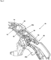
- the Figures 4 and 5 each show a preferred embodiment of the proposed switch 10, in particular its partial integration into the handle 52 of a machine tool 50.
- the switch 10 can be arranged predominantly inside two handle shells, wherein the handle shells form the handle 52 of the machine tool 50.
- Figure 4 shows an embodiment of the switch 10 with an unlocking device 38, in which Figure 5 For better visibility, fewer components of the handle 52 of the machine tool 50 are shown.
- the switching unit 48 with the circuit board 12 and the silicone layer 14 are visible, as well as their components, in particular the microswitches 16, 18 of the circuit board 12 and the membrane 22 and the blocking switch 20 of the silicone layer 14.
- the blocking switch 20 can be actuated directly by the user of the machine tool 50, while the membrane 22 can be actuated indirectly by the switching section 26a of the rotary lever 24 when the pistol grip section 28a of the rotary lever 24 is actuated, i.e. pulled, by the user of the machine tool 50.
- the rotary lever 24 is arranged so as to be rotatable about a pivot point 30, wherein the pivot point 30 divides the rotary lever 24 into a first side 26 and a second side 28.
- the rotary lever 24 is preferably not symmetrical, so that the sides 26, 28 of the rotary lever 24 do not correspond to one another or are similar.
- the pivot point 30 does not have to form the center of gravity of the rotary lever 24, for example.
- the switch 10 can, for example, comprise a housing.
Landscapes
- Engineering & Computer Science (AREA)
- Mechanical Engineering (AREA)
- Push-Button Switches (AREA)
Priority Applications (3)
| Application Number | Priority Date | Filing Date | Title |
|---|---|---|---|
| EP23181108.4A EP4480637A1 (fr) | 2023-06-23 | 2023-06-23 | Commutateur pour une machine-outil et procédé d'enclenchement d'une machine-outil |
| EP24180799.9A EP4480638A1 (fr) | 2023-06-23 | 2024-06-07 | Commutateur pour une machine-outil et procédé d'enclenchement d'une machine-outil |
| US18/738,190 US20240429003A1 (en) | 2023-06-23 | 2024-06-10 | Switch for a power tool and method for switching on a power tool |
Applications Claiming Priority (1)
| Application Number | Priority Date | Filing Date | Title |
|---|---|---|---|
| EP23181108.4A EP4480637A1 (fr) | 2023-06-23 | 2023-06-23 | Commutateur pour une machine-outil et procédé d'enclenchement d'une machine-outil |
Publications (1)
| Publication Number | Publication Date |
|---|---|
| EP4480637A1 true EP4480637A1 (fr) | 2024-12-25 |
Family
ID=87047652
Family Applications (2)
| Application Number | Title | Priority Date | Filing Date |
|---|---|---|---|
| EP23181108.4A Withdrawn EP4480637A1 (fr) | 2023-06-23 | 2023-06-23 | Commutateur pour une machine-outil et procédé d'enclenchement d'une machine-outil |
| EP24180799.9A Pending EP4480638A1 (fr) | 2023-06-23 | 2024-06-07 | Commutateur pour une machine-outil et procédé d'enclenchement d'une machine-outil |
Family Applications After (1)
| Application Number | Title | Priority Date | Filing Date |
|---|---|---|---|
| EP24180799.9A Pending EP4480638A1 (fr) | 2023-06-23 | 2024-06-07 | Commutateur pour une machine-outil et procédé d'enclenchement d'une machine-outil |
Country Status (2)
| Country | Link |
|---|---|
| US (1) | US20240429003A1 (fr) |
| EP (2) | EP4480637A1 (fr) |
Citations (5)
| Publication number | Priority date | Publication date | Assignee | Title |
|---|---|---|---|---|
| US20080011592A1 (en) * | 2006-06-29 | 2008-01-17 | Hilti Aktiengesellschaft | Main handle with a safety lock |
| US20170144289A1 (en) * | 2015-11-20 | 2017-05-25 | Max Co., Ltd. | Tool |
| WO2018077929A1 (fr) * | 2016-10-27 | 2018-05-03 | Hilti Aktiengesellschaft | Dispositif commutateur pour machine-outil |
| WO2019197123A1 (fr) | 2018-04-09 | 2019-10-17 | Hilti Aktiengesellschaft | Commutateur pour machine-outil et logique de commutation |
| WO2022117409A1 (fr) | 2020-12-04 | 2022-06-09 | Hilti Aktiengesellschaft | Poignée pour machine-outil, machine-outil et procédé de mise en marche, de mise hors circuit et de verrouillage de celle-ci |
-
2023
- 2023-06-23 EP EP23181108.4A patent/EP4480637A1/fr not_active Withdrawn
-
2024
- 2024-06-07 EP EP24180799.9A patent/EP4480638A1/fr active Pending
- 2024-06-10 US US18/738,190 patent/US20240429003A1/en active Pending
Patent Citations (6)
| Publication number | Priority date | Publication date | Assignee | Title |
|---|---|---|---|---|
| US20080011592A1 (en) * | 2006-06-29 | 2008-01-17 | Hilti Aktiengesellschaft | Main handle with a safety lock |
| US20170144289A1 (en) * | 2015-11-20 | 2017-05-25 | Max Co., Ltd. | Tool |
| WO2018077929A1 (fr) * | 2016-10-27 | 2018-05-03 | Hilti Aktiengesellschaft | Dispositif commutateur pour machine-outil |
| WO2019197123A1 (fr) | 2018-04-09 | 2019-10-17 | Hilti Aktiengesellschaft | Commutateur pour machine-outil et logique de commutation |
| WO2022117409A1 (fr) | 2020-12-04 | 2022-06-09 | Hilti Aktiengesellschaft | Poignée pour machine-outil, machine-outil et procédé de mise en marche, de mise hors circuit et de verrouillage de celle-ci |
| WO2022117311A1 (fr) | 2020-12-04 | 2022-06-09 | Hilti Aktiengesellschaft | Poignée pour machine-outil, machine-outil et procédé de mise en marche, de mise hors circuit et de verrouillage de celle-ci |
Also Published As
| Publication number | Publication date |
|---|---|
| EP4480638A1 (fr) | 2024-12-25 |
| US20240429003A1 (en) | 2024-12-26 |
Similar Documents
| Publication | Publication Date | Title |
|---|---|---|
| EP1523704B1 (fr) | Dispositif de commande d'un appareil | |
| DE69506840T2 (de) | Handbediengerät | |
| DE202010008031U1 (de) | Verriegelungs-Schaltervorrichtung für ein Kraftwerkzeug | |
| DE3040516A1 (de) | Sicherheitseinrichtung an einer motorsaege | |
| EP3533076B1 (fr) | Commutateur de machine-outil | |
| DE102016123093A1 (de) | Kleidungsstück, Verfahren zur Herstellung eines Handschuhs sowie Handschuhsatz | |
| DE3023691C2 (fr) | ||
| EP2210543A1 (fr) | Dispositif pour la coupe manuel de produits alimentaires | |
| EP4255684A1 (fr) | Poignée pour machine-outil, machine-outil et procédé de mise en marche, de mise hors circuit et de verrouillage de celle-ci | |
| EP1693334A1 (fr) | Dispositif de commande à main pour poste de conduite d'un chariot industriel | |
| EP4480638A1 (fr) | Commutateur pour une machine-outil et procédé d'enclenchement d'une machine-outil | |
| DE19958297B4 (de) | Elektrowerkzeug mit verbesserter Schaltervorrichtung | |
| EP0290073A1 (fr) | Rasoir à sec avec un volet roulant conlissant | |
| DE102019104671A1 (de) | Gerät zum entfernen eines joystick-griffs | |
| DE602004000215T2 (de) | Drucktastenschalter | |
| DE2736613C2 (de) | Totmannschalter | |
| DE3324545A1 (de) | Elektromotorisch betriebenes handgeraet | |
| DE602004013191T2 (de) | Elektrowerkzeug mit doppelt steuerbarem schalter | |
| DE7635497U1 (de) | Heckenschere mit elektromotorischem Antrieb | |
| DE69630097T2 (de) | Ein Schalter mit Ein- und Ausverriegelung | |
| DE3014553C2 (de) | Hilfsschalter zur Befestigung an handbetätigten Schutzschaltgeräten | |
| DE202017103878U1 (de) | Motorbetriebenes Arbeitsgerät, insbesondere Heckenschere | |
| DE3016615A1 (de) | Vorrichtung zum selbsttaetigen ausserbetriebsetzung einer handgefuehrten arbeitsmaschine | |
| DE19609940C2 (de) | Tastatur-Reinigungsgerät mit höheneinstellbaren Bürsten-Einsätzen im Druck- und Einrastverfahren | |
| DE202007018780U1 (de) | Sicherheitsmechanismus für eine Küchenmaschine mit Rührschüssel und Deckel |
Legal Events
| Date | Code | Title | Description |
|---|---|---|---|
| PUAI | Public reference made under article 153(3) epc to a published international application that has entered the european phase |
Free format text: ORIGINAL CODE: 0009012 |
|
| STAA | Information on the status of an ep patent application or granted ep patent |
Free format text: STATUS: THE APPLICATION HAS BEEN PUBLISHED |
|
| AK | Designated contracting states |
Kind code of ref document: A1 Designated state(s): AL AT BE BG CH CY CZ DE DK EE ES FI FR GB GR HR HU IE IS IT LI LT LU LV MC ME MK MT NL NO PL PT RO RS SE SI SK SM TR |
|
| STAA | Information on the status of an ep patent application or granted ep patent |
Free format text: STATUS: THE APPLICATION IS DEEMED TO BE WITHDRAWN |
|
| 18D | Application deemed to be withdrawn |
Effective date: 20250626 |