EP4480672A1 - Reparaturverfahren mittels plasmaätzen - Google Patents
Reparaturverfahren mittels plasmaätzen Download PDFInfo
- Publication number
- EP4480672A1 EP4480672A1 EP24180205.7A EP24180205A EP4480672A1 EP 4480672 A1 EP4480672 A1 EP 4480672A1 EP 24180205 A EP24180205 A EP 24180205A EP 4480672 A1 EP4480672 A1 EP 4480672A1
- Authority
- EP
- European Patent Office
- Prior art keywords
- coating
- elastomeric
- repair
- recited
- plasma etching
- Prior art date
- Legal status (The legal status is an assumption and is not a legal conclusion. Google has not performed a legal analysis and makes no representation as to the accuracy of the status listed.)
- Granted
Links
Images

Classifications
-
- B—PERFORMING OPERATIONS; TRANSPORTING
- B29—WORKING OF PLASTICS; WORKING OF SUBSTANCES IN A PLASTIC STATE IN GENERAL
- B29C—SHAPING OR JOINING OF PLASTICS; SHAPING OF MATERIAL IN A PLASTIC STATE, NOT OTHERWISE PROVIDED FOR; AFTER-TREATMENT OF THE SHAPED PRODUCTS, e.g. REPAIRING
- B29C59/00—Surface shaping of articles, e.g. embossing; Apparatus therefor
- B29C59/14—Surface shaping of articles, e.g. embossing; Apparatus therefor by plasma treatment
-
- B—PERFORMING OPERATIONS; TRANSPORTING
- B05—SPRAYING OR ATOMISING IN GENERAL; APPLYING FLUENT MATERIALS TO SURFACES, IN GENERAL
- B05D—PROCESSES FOR APPLYING FLUENT MATERIALS TO SURFACES, IN GENERAL
- B05D3/00—Pretreatment of surfaces to which liquids or other fluent materials are to be applied; After-treatment of applied coatings, e.g. intermediate treating of an applied coating preparatory to subsequent applications of liquids or other fluent materials
- B05D3/14—Pretreatment of surfaces to which liquids or other fluent materials are to be applied; After-treatment of applied coatings, e.g. intermediate treating of an applied coating preparatory to subsequent applications of liquids or other fluent materials by electrical means
- B05D3/141—Plasma treatment
- B05D3/142—Pretreatment
-
- B—PERFORMING OPERATIONS; TRANSPORTING
- B05—SPRAYING OR ATOMISING IN GENERAL; APPLYING FLUENT MATERIALS TO SURFACES, IN GENERAL
- B05D—PROCESSES FOR APPLYING FLUENT MATERIALS TO SURFACES, IN GENERAL
- B05D5/00—Processes for applying liquids or other fluent materials to surfaces to obtain special surface effects, finishes or structures
- B05D5/005—Repairing damaged coatings
-
- F—MECHANICAL ENGINEERING; LIGHTING; HEATING; WEAPONS; BLASTING
- F01—MACHINES OR ENGINES IN GENERAL; ENGINE PLANTS IN GENERAL; STEAM ENGINES
- F01D—NON-POSITIVE DISPLACEMENT MACHINES OR ENGINES, e.g. STEAM TURBINES
- F01D5/00—Blades; Blade-carrying members; Heating, heat-insulating, cooling or antivibration means on the blades or the members
- F01D5/005—Repairing methods or devices
-
- F—MECHANICAL ENGINEERING; LIGHTING; HEATING; WEAPONS; BLASTING
- F01—MACHINES OR ENGINES IN GENERAL; ENGINE PLANTS IN GENERAL; STEAM ENGINES
- F01D—NON-POSITIVE DISPLACEMENT MACHINES OR ENGINES, e.g. STEAM TURBINES
- F01D5/00—Blades; Blade-carrying members; Heating, heat-insulating, cooling or antivibration means on the blades or the members
- F01D5/12—Blades
- F01D5/28—Selecting particular materials; Particular measures relating thereto; Measures against erosion or corrosion
- F01D5/288—Protective coatings for blades
-
- B—PERFORMING OPERATIONS; TRANSPORTING
- B05—SPRAYING OR ATOMISING IN GENERAL; APPLYING FLUENT MATERIALS TO SURFACES, IN GENERAL
- B05D—PROCESSES FOR APPLYING FLUENT MATERIALS TO SURFACES, IN GENERAL
- B05D2202/00—Metallic substrate
- B05D2202/20—Metallic substrate based on light metals
- B05D2202/25—Metallic substrate based on light metals based on Al
-
- B—PERFORMING OPERATIONS; TRANSPORTING
- B05—SPRAYING OR ATOMISING IN GENERAL; APPLYING FLUENT MATERIALS TO SURFACES, IN GENERAL
- B05D—PROCESSES FOR APPLYING FLUENT MATERIALS TO SURFACES, IN GENERAL
- B05D2530/00—Rubber or the like
-
- B—PERFORMING OPERATIONS; TRANSPORTING
- B29—WORKING OF PLASTICS; WORKING OF SUBSTANCES IN A PLASTIC STATE IN GENERAL
- B29C—SHAPING OR JOINING OF PLASTICS; SHAPING OF MATERIAL IN A PLASTIC STATE, NOT OTHERWISE PROVIDED FOR; AFTER-TREATMENT OF THE SHAPED PRODUCTS, e.g. REPAIRING
- B29C73/00—Repairing of articles made from plastics or substances in a plastic state, e.g. of articles shaped or produced by using techniques covered by this subclass or subclass B29D
- B29C73/02—Repairing of articles made from plastics or substances in a plastic state, e.g. of articles shaped or produced by using techniques covered by this subclass or subclass B29D using liquid or paste-like material
-
- B—PERFORMING OPERATIONS; TRANSPORTING
- B29—WORKING OF PLASTICS; WORKING OF SUBSTANCES IN A PLASTIC STATE IN GENERAL
- B29L—INDEXING SCHEME ASSOCIATED WITH SUBCLASS B29C, RELATING TO PARTICULAR ARTICLES
- B29L2031/00—Other particular articles
- B29L2031/08—Blades for rotors, stators, fans, turbines or the like, e.g. screw propellers
-
- F—MECHANICAL ENGINEERING; LIGHTING; HEATING; WEAPONS; BLASTING
- F05—INDEXING SCHEMES RELATING TO ENGINES OR PUMPS IN VARIOUS SUBCLASSES OF CLASSES F01-F04
- F05D—INDEXING SCHEME FOR ASPECTS RELATING TO NON-POSITIVE-DISPLACEMENT MACHINES OR ENGINES, GAS-TURBINES OR JET-PROPULSION PLANTS
- F05D2220/00—Application
- F05D2220/30—Application in turbines
- F05D2220/36—Application in turbines specially adapted for the fan of turbofan engines
-
- F—MECHANICAL ENGINEERING; LIGHTING; HEATING; WEAPONS; BLASTING
- F05—INDEXING SCHEMES RELATING TO ENGINES OR PUMPS IN VARIOUS SUBCLASSES OF CLASSES F01-F04
- F05D—INDEXING SCHEME FOR ASPECTS RELATING TO NON-POSITIVE-DISPLACEMENT MACHINES OR ENGINES, GAS-TURBINES OR JET-PROPULSION PLANTS
- F05D2230/00—Manufacture
- F05D2230/10—Manufacture by removing material
- F05D2230/12—Manufacture by removing material by spark erosion methods
-
- F—MECHANICAL ENGINEERING; LIGHTING; HEATING; WEAPONS; BLASTING
- F05—INDEXING SCHEMES RELATING TO ENGINES OR PUMPS IN VARIOUS SUBCLASSES OF CLASSES F01-F04
- F05D—INDEXING SCHEME FOR ASPECTS RELATING TO NON-POSITIVE-DISPLACEMENT MACHINES OR ENGINES, GAS-TURBINES OR JET-PROPULSION PLANTS
- F05D2230/00—Manufacture
- F05D2230/80—Repairing, retrofitting or upgrading methods
-
- F—MECHANICAL ENGINEERING; LIGHTING; HEATING; WEAPONS; BLASTING
- F05—INDEXING SCHEMES RELATING TO ENGINES OR PUMPS IN VARIOUS SUBCLASSES OF CLASSES F01-F04
- F05D—INDEXING SCHEME FOR ASPECTS RELATING TO NON-POSITIVE-DISPLACEMENT MACHINES OR ENGINES, GAS-TURBINES OR JET-PROPULSION PLANTS
- F05D2230/00—Manufacture
- F05D2230/90—Coating; Surface treatment
-
- F—MECHANICAL ENGINEERING; LIGHTING; HEATING; WEAPONS; BLASTING
- F05—INDEXING SCHEMES RELATING TO ENGINES OR PUMPS IN VARIOUS SUBCLASSES OF CLASSES F01-F04
- F05D—INDEXING SCHEME FOR ASPECTS RELATING TO NON-POSITIVE-DISPLACEMENT MACHINES OR ENGINES, GAS-TURBINES OR JET-PROPULSION PLANTS
- F05D2300/00—Materials; Properties thereof
- F05D2300/10—Metals, alloys or intermetallic compounds
- F05D2300/12—Light metals
- F05D2300/121—Aluminium
-
- F—MECHANICAL ENGINEERING; LIGHTING; HEATING; WEAPONS; BLASTING
- F05—INDEXING SCHEMES RELATING TO ENGINES OR PUMPS IN VARIOUS SUBCLASSES OF CLASSES F01-F04
- F05D—INDEXING SCHEME FOR ASPECTS RELATING TO NON-POSITIVE-DISPLACEMENT MACHINES OR ENGINES, GAS-TURBINES OR JET-PROPULSION PLANTS
- F05D2300/00—Materials; Properties thereof
- F05D2300/40—Organic materials
- F05D2300/43—Synthetic polymers, e.g. plastics; Rubber
-
- F—MECHANICAL ENGINEERING; LIGHTING; HEATING; WEAPONS; BLASTING
- F05—INDEXING SCHEMES RELATING TO ENGINES OR PUMPS IN VARIOUS SUBCLASSES OF CLASSES F01-F04
- F05D—INDEXING SCHEME FOR ASPECTS RELATING TO NON-POSITIVE-DISPLACEMENT MACHINES OR ENGINES, GAS-TURBINES OR JET-PROPULSION PLANTS
- F05D2300/00—Materials; Properties thereof
- F05D2300/40—Organic materials
- F05D2300/43—Synthetic polymers, e.g. plastics; Rubber
- F05D2300/431—Rubber
-
- F—MECHANICAL ENGINEERING; LIGHTING; HEATING; WEAPONS; BLASTING
- F05—INDEXING SCHEMES RELATING TO ENGINES OR PUMPS IN VARIOUS SUBCLASSES OF CLASSES F01-F04
- F05D—INDEXING SCHEME FOR ASPECTS RELATING TO NON-POSITIVE-DISPLACEMENT MACHINES OR ENGINES, GAS-TURBINES OR JET-PROPULSION PLANTS
- F05D2300/00—Materials; Properties thereof
- F05D2300/40—Organic materials
- F05D2300/43—Synthetic polymers, e.g. plastics; Rubber
- F05D2300/437—Silicon polymers
-
- F—MECHANICAL ENGINEERING; LIGHTING; HEATING; WEAPONS; BLASTING
- F05—INDEXING SCHEMES RELATING TO ENGINES OR PUMPS IN VARIOUS SUBCLASSES OF CLASSES F01-F04
- F05D—INDEXING SCHEME FOR ASPECTS RELATING TO NON-POSITIVE-DISPLACEMENT MACHINES OR ENGINES, GAS-TURBINES OR JET-PROPULSION PLANTS
- F05D2300/00—Materials; Properties thereof
- F05D2300/60—Properties or characteristics given to material by treatment or manufacturing
- F05D2300/611—Coating
Definitions
- Gas turbine engines such as those that power modern commercial aircraft, include a fan section for propulsion, a compressor section to pressurize a supply of air from the fan section, a combustor section to burn a hydrocarbon fuel in the presence of the pressurized air, and a turbine section to extract energy from the resultant combustion gases in order to power the compressor and fan sections.
- the fan includes an array of fan blades that each have an aerodynamic surface contour.
- the blades may be formed from a composite, a metallic material, or combinations of these materials.
- a sheath is often secured to the leading edge of the blade to protect against impact from foreign debris inj ested into the engine.
- the blades may also have an erosion-resistant coating to protect the surfaces of the blade from being eroded from foreign debris.
- a repair process includes providing a gas turbine engine article that has an elastomeric coating that has an eroded region, plasma etching the elastomeric coating in the eroded region, and applying an elastomeric repair coating on the eroded region.
- the gas turbine engine article is a fan blade.
- the plasma etching partially removes a surface portion of the elastomeric coating to create a new bonding surface on which the elastomeric repair coating is applied.
- the elastomeric repair coating has an interfacial tensile strength with respect to the bonding surface of more than 1500 pounds per square inch (psi) (10.3 MPa).
- the elastomeric coating is selected from the group consisting of silicone, urethane, fluoroelastomer, and combinations thereof.
- the plasma etching is conducted under an air, oxygen or argon plasma.
- the plasma etching is conducted for a time from 5 minutes to 60 minutes.
- the plasma etching is conducted for a time from 20 minutes to 60 minutes.
- the elastomeric repair coating on the eroded region is flush with the elastomeric coating adjacent the eroded region.
- a gas turbine engine article includes a substrate, and an elastomeric coating disposed on the substrate.
- the elastomeric coating has a region in which a surface portion has been removed to create a bonding surface, and an elastomeric repair coating disposed on the bonding surface.
- the elastomeric repair coating has an interfacial tensile strength with respect to the bonding surface of more than 1500 pounds per square inch (psi) (10.3 MPa).
- the substrate is an aluminum alloy.
- the elastomeric coating is selected from the group consisting of silicone, urethane, fluoroelastomer, and combinations thereof.
- the elastomeric coating is fluoroelastomer and the elastomeric repair coating is silicone.
- the present disclosure may include any one or more of the individual features disclosed above and/or below alone or in any combination thereof.
- FIG. 1 schematically illustrates a gas turbine engine 20.
- the gas turbine engine 20 is disclosed herein as a two-spool turbofan that generally incorporates a fan section 22, a compressor section 24, a combustor section 26 and a turbine section 28.
- the fan section 22 includes a row of fan blades 23 that drive air along a bypass flow path B in a bypass duct defined within a housing 15 such as a fan case or nacelle, and also drives air along a core flow path C for compression and communication into the combustor section 26 then expansion through the turbine section 28.
- the exemplary engine 20 generally includes a low speed spool 30 and a high speed spool 32 mounted for rotation about an engine central longitudinal axis A relative to an engine static structure 36 via several bearing systems 38. It should be understood that various bearing systems 38 at various locations may alternatively or additionally be provided, and the location of bearing systems 38 may be varied as appropriate to the application.
- the low speed spool 30 generally includes an inner shaft 40 that interconnects, a first (or low) pressure compressor 44 and a first (or low) pressure turbine 46.
- the inner shaft 40 is connected to the fan section 22 through a speed change mechanism, which in exemplary gas turbine engine 20 is illustrated as a geared architecture 48 to drive a fan section 22 at a lower speed than the low speed spool 30.
- the high speed spool 32 includes an outer shaft 50 that interconnects a second (or high) pressure compressor 52 and a second (or high) pressure turbine 54.
- a combustor 56 is arranged in the exemplary gas turbine 20 between the high pressure compressor 52 and the high pressure turbine 54.
- a mid-turbine frame 57 of the engine static structure 36 may be arranged generally between the high pressure turbine 54 and the low pressure turbine 46.
- the mid-turbine frame 57 further supports bearing systems 38 in the turbine section 28.
- the inner shaft 40 and the outer shaft 50 are concentric and rotate via bearing systems 38 about the engine central longitudinal axis A which is collinear with their longitudinal axes.
- the core airflow is compressed by the low pressure compressor 44 then the high pressure compressor 52, mixed and burned with fuel in the combustor 56, then expanded through the high pressure turbine 54 and low pressure turbine 46.
- the mid-turbine frame 57 includes airfoils 59 which are in the core airflow path C.
- the turbines 46, 54 rotationally drive the respective low speed spool 30 and high speed spool 32 in response to the expansion. It will be appreciated that each of the positions of the fan section 22, compressor section 24, combustor section 26, turbine section 28, and fan drive gear system 48 may be varied.
- gear system 48 may be located aft of the low pressure compressor, or aft of the combustor section 26 or even aft of turbine section 28, and fan section 22 may be positioned forward or aft of the location of gear system 48.
- the engine 20 in one example is a high-bypass geared aircraft engine.
- the engine 20 bypass ratio is greater than about six (6), with an example embodiment being greater than about ten (10), and can be less than or equal to about 18.0, or more narrowly can be less than or equal to 16.0.
- the geared architecture 48 is an epicyclic gear train, such as a planetary gear system or other gear system, with a gear reduction ratio of greater than about 2.3.
- the gear reduction ratio may be less than or equal to 4.0.
- the low pressure turbine 46 has a pressure ratio that is greater than about five.
- the low pressure turbine pressure ratio can be less than or equal to 13.0, or more narrowly less than or equal to 12.0.
- the engine 20 bypass ratio is greater than about ten (10:1)
- the fan diameter is significantly larger than that of the low pressure compressor 44
- the low pressure turbine 46 has a pressure ratio that is greater than about five 5:1.
- Low pressure turbine 46 pressure ratio is pressure measured prior to an inlet of low pressure turbine 46 as related to the pressure at the outlet of the low pressure turbine 46 prior to an exhaust nozzle.
- the geared architecture 48 may be an epicycle gear train, such as a planetary gear system or other gear system, with a gear reduction ratio of greater than about 2.3:1 and less than about 5:1. It should be understood, however, that the above parameters are only exemplary of one embodiment of a geared architecture engine and that the present invention is applicable to other gas turbine engines including direct drive turbofans.
- the fan section 22 of the engine 20 is designed for a particular flight condition -- typically cruise at about 0.8 Mach and about 35,000 feet (10,668 meters).
- the flight condition of 0.8 Mach and 35,000 ft (10,668 meters), with the engine at its best fuel consumption - also known as "bucket cruise Thrust Specific Fuel Consumption ('TSFC')" - is the industry standard parameter of lbm of fuel being burned divided by lbf of thrust the engine produces at that minimum point.
- 'TSFC' Thrust Specific Fuel Consumption
- “Low fan pressure ratio” is the pressure ratio across the fan blade alone, without a Fan Exit Guide Vane (“FEGV”) system.
- the low fan pressure ratio as disclosed herein according to one non-limiting embodiment is less than about 1.45, or more narrowly greater than or equal to 1.25.
- Low corrected fan tip speed is the actual fan tip speed in ft/sec divided by an industry standard temperature correction of [(Tram °R) / (518.7 °R)] 0.5 .
- the "Low corrected fan tip speed" as disclosed herein according to one non-limiting embodiment is less than about 1150.0 ft / second (350.5 meters/second), and can be greater than or equal to 1000.0 ft / second (304.8 meters/second).
- FIG. 2 illustrates a representative one of the fan blades 23.
- the blade 23 includes a root section 62 for attaching the blade 23 (gas turbine engine article), such as to a hub in the fan section 22, and an airfoil section 64 that extends radially from the root section 62.
- the airfoil section 64 defines leading and trailing edges 64a/64b.
- a metallic sheath 65 is attached on the leading edge 64a for protecting against foreign object impact.
- the blade 23 in this example is formed of an aluminum alloy, but may alternatively be formed of other alloys or composite materials.
- the remainder of the airfoil section 64, including the sides and trailing edge 64b, includes an elastomeric coating 66 that is disposed on the underlying aluminum alloy.
- a primer layer (not shown) is applied onto the aluminum alloy to promote adhesion of the elastomeric coating 66.
- the elastomer coating 66 is erosion resistant and protects the underlying alloy from being eroded by foreign objects (e.g., sand) ingested into the engine 20.
- the elastomeric coating 66 is a silicone coating, a urethane coating, or a fluroelastomer coating, but is not limited thereto.
- the elastomeric coating 66 can be subject to damage from erosion over time. As the blades 23 in general are expensive to manufacture, it is desirable to be able to repair such damage rather than replace a damaged blade with a new blade.
- One strategy for repair is to abrade the coating, remove the damaged coating material, and then re-apply a primer as needed and a new surface coating.
- Such a repair requires removing the eroded coating portion by grit-blasting or sanding, which can leave debris on the repair pre-bond surface, which in turn can debit adhesion and durability of the new repair coating.
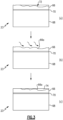
- Fig. 3 depicts a repair process that avoids grit-blasting or the like, while providing strong adhesion for good durability. It is to be appreciated that although the process is described with respect to the blade 23, the process may be applied to other gas turbine engine articles that include such elastomeric coatings that require repair.
- the blade 23 includes the aluminum alloy substrate 68, a primer layer 70 on the substrate 68, and the elastomeric coating 66 on the primer layer 70.
- the elastomeric coating 66 includes an eroded region 72.
- the eroded region 72 is a region of the coating 66 which has been lost due to erosion, typically during use of the blade 23 in the engine 20 during service.
- the coating 66 is thinner at the eroded region 72 in comparison to the initial thickness of the coating 66, shown by the dashed lines in the figure.
- Such erosion can occur from sand or other debris entrained in the air that flows across the blade 23.
- the eroded region 72 is then subjected to a plasma etching treatment.
- the eroded region may be cleaned with a solvent, such as an acetone wipe or isopropanol wipe and, optionally, light abrasion.
- the plasma etching is conducted under an oxygen, air or argon gas environment.
- the excited ions of the plasma bombards the surface of the eroded region of the coating 66.
- the ions physically and chemically interact with the molecules at the surface of the coating 66, thereby causing vaporization and oxidation (under oxygen or air) at the surface.
- Plasma etching may be used to clean surfaces.
- a relatively long process plasma etching process time is used to facilitate removal of a surface portion of the coating 66 and to activate the surface by oxidation to create a new bonding surface 66a.
- a low pressure plasma etching is conducted for a time from 5 minutes to 60 minutes. Etching times toward the higher end of the range are used to ensure ample removal of debris and sufficient surface activation for better repair bonding, such as from 20 minutes to 60 minutes.
- an elastomeric repair coating 74 is then applied on the new bonding surface 66a.
- the elastomeric repair coating 74 is a urethane coating.
- the repair coating 74 may be applied as a liquid and then cured, such as in air and/or at an elevated temperature.
- the repair coating 74 is smoothed or otherwise molded such that the repair coating 74 is flush with the elastomeric coating 66 adjacent the eroded region 72 in order to maintain the aerodynamic surface profile of the blade 23.
- the repair coating 74 can be a solid coating and a layer of adhesive may be applied on the plasma treated surface prior to applying the repair coating 74 and curing at room temperature or at an elevated temperature.
- the repair coating 74 Due to the removal of embedded debris and activation of the surface 66a, the repair coating 74 forms a strong bond with the underlying coating 66, even where the coating 66 is of a different type than the repair coating 74.
- the repair coating 74 can be used on a variety of different types of original elastomeric coatings 66, such as silicone, urethane, or fluoroelastomer.
- the elastomeric repair coating 74 has an interfacial tensile strength with respect to the bonding surface 66a of more than 1500 pounds per square inch (psi) (10.3 MPa), as determined by a button pull off test (e.g., per ASTM D7234).
- a button of known area is bonded to the repair coating 74.
- the button is then pulled while measuring the pull force to determine a stress at which failure occurs. If the repair coating 74 is strongly bonded, failure will occur at other material layers or interface (e.g., the interface between the primer layer and the coating 66 or within primer layer) rather than the bonding interface between the repair coating 74 and the coating 66.
- the maximum stress at which such failure occurs at another interface indicates that the strength at bonding interface between the repair coating 74 and the coating 66 is greater than that maximum stress.
- a repair was conducted in accordance with the description above in which a low pressure plasma etching was conducted in air under a plasma power of approximately 2 kW for 20 minutes.
- a urethane erosion coating was applied on the plasma treated repair surface and then cured at room temperature for 5 days.
- An aluminum button with an area of approximately 150 mm 2 was then bonded to the repair coating using a paste epoxy. The button was then subjected to a pulling force at 150 psi/sec (1.03 MPa/s). Failure occurred within the primer or primer / erosion coating interface (not the interface between the repair coating and the original coating) at approximately 2750 psi (19.0 MPa).
- a repair was conducted in accordance with the description above in which a low pressure plasma etching was conducted in air under a plasma power of approximately 2 kW for 40 minutes.
- a urethane erosion coating was applied on the plasma treated repair surface and then cured at room temperature for 5 days.
- An aluminum button with an area of approximately 150 mm 2 was then bonded to the repair coating using a paste epoxy. The button was then subjected to a pulling force at 150 psi/sec (1.03 MPA/s). Failure occurred within the primer or primer / erosion coating interface (not the interface between the repair coating and the original coating) at approximately 3400 psi (23.4 MPa).
Landscapes
- Engineering & Computer Science (AREA)
- Mechanical Engineering (AREA)
- General Engineering & Computer Science (AREA)
- Physics & Mathematics (AREA)
- Plasma & Fusion (AREA)
- Chemical & Material Sciences (AREA)
- Materials Engineering (AREA)
- Structures Of Non-Positive Displacement Pumps (AREA)
Applications Claiming Priority (1)
| Application Number | Priority Date | Filing Date | Title |
|---|---|---|---|
| US18/336,933 US12392244B2 (en) | 2023-06-16 | 2023-06-16 | Repair process using plasma etching |
Publications (2)
| Publication Number | Publication Date |
|---|---|
| EP4480672A1 true EP4480672A1 (de) | 2024-12-25 |
| EP4480672B1 EP4480672B1 (de) | 2026-03-25 |
Family
ID=91431390
Family Applications (1)
| Application Number | Title | Priority Date | Filing Date |
|---|---|---|---|
| EP24180205.7A Active EP4480672B1 (de) | 2023-06-16 | 2024-06-05 | Reparaturverfahren mittels plasmaätzen |
Country Status (2)
| Country | Link |
|---|---|
| US (1) | US12392244B2 (de) |
| EP (1) | EP4480672B1 (de) |
Citations (3)
| Publication number | Priority date | Publication date | Assignee | Title |
|---|---|---|---|---|
| US20070231156A1 (en) * | 2005-12-14 | 2007-10-04 | Hontek Corporation | Method and coating for protecting and repairing an airfoil surface |
| DE102017223600A1 (de) * | 2017-12-21 | 2019-06-27 | Siemens Aktiengesellschaft | Verfahren und Vorrichtung zum Reinigen eines eine Materialschädigung aufweisenden Substrats |
| EP3184180B1 (de) * | 2015-12-24 | 2020-06-10 | United Technologies Corporation | Lokale reparatur oder wiederaufarbeitung von polymer-erosionsbeschichtungen |
Family Cites Families (18)
| Publication number | Priority date | Publication date | Assignee | Title |
|---|---|---|---|---|
| US20010014409A1 (en) * | 1997-04-04 | 2001-08-16 | Cohen Adam L. | Article, method, and apparatus for electrochemical fabrication |
| US6605160B2 (en) * | 2000-08-21 | 2003-08-12 | Robert Frank Hoskin | Repair of coatings and surfaces using reactive metals coating processes |
| US7008553B2 (en) * | 2003-01-09 | 2006-03-07 | General Electric Company | Method for removing aluminide coating from metal substrate and turbine engine part so treated |
| US8709545B2 (en) | 2009-01-30 | 2014-04-29 | The Boeing Company | Hybrid coatings and associated methods of application |
| JP2011072895A (ja) * | 2009-09-30 | 2011-04-14 | Basf Coatings Japan Ltd | 耐すり傷性塗膜の部分補修方法 |
| SG173932A1 (en) * | 2010-02-25 | 2011-09-29 | United Technologies Corp | Repair of a coating on a turbine component |
| US20120148769A1 (en) * | 2010-12-13 | 2012-06-14 | General Electric Company | Method of fabricating a component using a two-layer structural coating |
| KR101343415B1 (ko) * | 2011-05-31 | 2013-12-20 | 국방과학연구소 | 다층 폴리우레탄 구조물 및 이의 제조방법 |
| CN102680527B (zh) * | 2012-05-23 | 2014-03-26 | 哈尔滨工业大学 | 一种基于纳米软印刷技术批量制备石墨烯气体传感器的方法 |
| US9670304B2 (en) * | 2012-11-05 | 2017-06-06 | Liang Wang | Composite for preventing ice adhesion |
| WO2014143224A1 (en) | 2013-03-15 | 2014-09-18 | United Technologies Corporation | Turbine engine repair methods |
| WO2015026798A1 (en) * | 2013-08-20 | 2015-02-26 | United Technologies Corporation | Replacing an aperture with an annular bushing in a composite laminated composite component |
| EP2840101A1 (de) * | 2013-08-23 | 2015-02-25 | BASF Coatings GmbH | Dimerfettsäure-haltiges Reaktionsprodukt und ein das Reaktionsprodukt enhaltendes Beschichtungsmittel |
| US10927684B2 (en) * | 2016-02-08 | 2021-02-23 | Raytheon Technologies Corporation | Repairing a coating with a pre-configured coating patch |
| CN109317377A (zh) * | 2018-11-22 | 2019-02-12 | 中国航发沈阳黎明航空发动机有限责任公司 | 发动机尾喷口零件中低温多频段兼容涂层涂覆和返修方法 |
| CN111229566A (zh) * | 2020-03-31 | 2020-06-05 | 国家电网有限公司 | 水轮机过流部件气蚀缺陷修复涂层及其制备方法 |
| US11408371B1 (en) * | 2021-04-15 | 2022-08-09 | Raytheon Technologies Corporation | Fluoroelastomer erosion coating repair |
| CN113928034A (zh) * | 2021-10-13 | 2022-01-14 | 石家庄沃佳玛智能科技有限公司 | 一种耐刮擦热转印色带制作方法 |
-
2023
- 2023-06-16 US US18/336,933 patent/US12392244B2/en active Active
-
2024
- 2024-06-05 EP EP24180205.7A patent/EP4480672B1/de active Active
Patent Citations (3)
| Publication number | Priority date | Publication date | Assignee | Title |
|---|---|---|---|---|
| US20070231156A1 (en) * | 2005-12-14 | 2007-10-04 | Hontek Corporation | Method and coating for protecting and repairing an airfoil surface |
| EP3184180B1 (de) * | 2015-12-24 | 2020-06-10 | United Technologies Corporation | Lokale reparatur oder wiederaufarbeitung von polymer-erosionsbeschichtungen |
| DE102017223600A1 (de) * | 2017-12-21 | 2019-06-27 | Siemens Aktiengesellschaft | Verfahren und Vorrichtung zum Reinigen eines eine Materialschädigung aufweisenden Substrats |
Also Published As
| Publication number | Publication date |
|---|---|
| US12392244B2 (en) | 2025-08-19 |
| EP4480672B1 (de) | 2026-03-25 |
| US20240418088A1 (en) | 2024-12-19 |
Similar Documents
| Publication | Publication Date | Title |
|---|---|---|
| US10260351B2 (en) | Fan blade and method of manufacturing same | |
| US8721294B2 (en) | Airfoil with galvanically isolated metal coating | |
| EP3431712B1 (de) | Verfahren zum abziehen und erneuten beschichten von erosionsbeschichtungen auf gebläseschaufeln und strukturellen leitschaufeln | |
| US20140010663A1 (en) | Gas turbine engine fan blade tip treatment | |
| US10508549B2 (en) | Gas turbine engine airfoil with large thickness properties | |
| EP3049635B1 (de) | Aluminiumschaufel mit titanbeschichtung | |
| US20200063584A1 (en) | Airfoil with seal between endwall and airfoil section | |
| US11260421B2 (en) | Method to strip and recoat erosion coatings applied to fan blades and structural guide vanes | |
| US10273816B2 (en) | Wear pad to prevent cracking of fan blade | |
| US10458255B2 (en) | Removable film for airfoil surfaces | |
| EP4480672B1 (de) | Reparaturverfahren mittels plasmaätzen | |
| US20140248156A1 (en) | Composite Articles and Methods | |
| US20140219808A1 (en) | Sheath with extended wings | |
| EP3323986B1 (de) | Schaufel mit geometrisch segmentiertem beschichtungsabschnitt | |
| EP3467260A1 (de) | Gasturbinentriebwerksschaufel mit gekrümmter schaufelspitze | |
| EP3323996A1 (de) | Turbinenmotorkomponente mit geometrisch segmentiertem beschichtungsabschnitt und kühlkanal | |
| EP3477055A1 (de) | Gasturbinenmotorschaufel | |
| EP4317109A1 (de) | Keramikmatrixverbundartikel und verfahren zur herstellung davon | |
| EP4663955A1 (de) | In-situ-galvanisierte ummantelung für bläserschaufel aus verbundwerkstoff | |
| CN119532033A (zh) | 修复发动机多层部件的系统和方法 |
Legal Events
| Date | Code | Title | Description |
|---|---|---|---|
| PUAI | Public reference made under article 153(3) epc to a published international application that has entered the european phase |
Free format text: ORIGINAL CODE: 0009012 |
|
| STAA | Information on the status of an ep patent application or granted ep patent |
Free format text: STATUS: THE APPLICATION HAS BEEN PUBLISHED |
|
| AK | Designated contracting states |
Kind code of ref document: A1 Designated state(s): AL AT BE BG CH CY CZ DE DK EE ES FI FR GB GR HR HU IE IS IT LI LT LU LV MC ME MK MT NL NO PL PT RO RS SE SI SK SM TR |
|
| STAA | Information on the status of an ep patent application or granted ep patent |
Free format text: STATUS: REQUEST FOR EXAMINATION WAS MADE |
|
| 17P | Request for examination filed |
Effective date: 20250624 |
|
| GRAP | Despatch of communication of intention to grant a patent |
Free format text: ORIGINAL CODE: EPIDOSNIGR1 |
|
| STAA | Information on the status of an ep patent application or granted ep patent |
Free format text: STATUS: GRANT OF PATENT IS INTENDED |
|
| RIC1 | Information provided on ipc code assigned before grant |
Ipc: B29C 59/14 20060101AFI20251015BHEP Ipc: B05D 5/00 20060101ALI20251015BHEP Ipc: F01D 5/00 20060101ALI20251015BHEP Ipc: F01D 5/28 20060101ALN20251015BHEP Ipc: B29C 73/02 20060101ALN20251015BHEP |
|
| INTG | Intention to grant announced |
Effective date: 20251027 |
|
| GRAS | Grant fee paid |
Free format text: ORIGINAL CODE: EPIDOSNIGR3 |
|
| GRAA | (expected) grant |
Free format text: ORIGINAL CODE: 0009210 |
|
| STAA | Information on the status of an ep patent application or granted ep patent |
Free format text: STATUS: THE PATENT HAS BEEN GRANTED |
|
| AK | Designated contracting states |
Kind code of ref document: B1 Designated state(s): AL AT BE BG CH CY CZ DE DK EE ES FI FR GB GR HR HU IE IS IT LI LT LU LV MC ME MK MT NL NO PL PT RO RS SE SI SK SM TR |
|
| REG | Reference to a national code |
Ref country code: CH Ref legal event code: F10 Free format text: ST27 STATUS EVENT CODE: U-0-0-F10-F00 (AS PROVIDED BY THE NATIONAL OFFICE) Effective date: 20260325 Ref country code: GB Ref legal event code: FG4D |
|
| REG | Reference to a national code |
Ref country code: DE Ref legal event code: R096 Ref document number: 602024003372 Country of ref document: DE |
|
| REG | Reference to a national code |
Ref country code: IE Ref legal event code: FG4D |