EP4480714A1 - Verfahren zur herstellung einer sicherheitsvorrichtung mit mindestens einem ersten, unter einem ersten winkel sichtbaren bild und einem zweiten, unter einem zweiten winkel sichtbaren bild, durch das verfahren erhaltene sicherheitsvorrichtung und ein die sicherheitsvorrichtung enthaltendes identitätsdokument - Google Patents
Verfahren zur herstellung einer sicherheitsvorrichtung mit mindestens einem ersten, unter einem ersten winkel sichtbaren bild und einem zweiten, unter einem zweiten winkel sichtbaren bild, durch das verfahren erhaltene sicherheitsvorrichtung und ein die sicherheitsvorrichtung enthaltendes identitätsdokument Download PDFInfo
- Publication number
- EP4480714A1 EP4480714A1 EP24180691.8A EP24180691A EP4480714A1 EP 4480714 A1 EP4480714 A1 EP 4480714A1 EP 24180691 A EP24180691 A EP 24180691A EP 4480714 A1 EP4480714 A1 EP 4480714A1
- Authority
- EP
- European Patent Office
- Prior art keywords
- radiation
- pattern
- under
- metal patch
- perforation
- Prior art date
- Legal status (The legal status is an assumption and is not a legal conclusion. Google has not performed a legal analysis and makes no representation as to the accuracy of the status listed.)
- Pending
Links
Images




Classifications
-
- B—PERFORMING OPERATIONS; TRANSPORTING
- B42—BOOKBINDING; ALBUMS; FILES; SPECIAL PRINTED MATTER
- B42D—BOOKS; BOOK COVERS; LOOSE LEAVES; PRINTED MATTER CHARACTERISED BY IDENTIFICATION OR SECURITY FEATURES; PRINTED MATTER OF SPECIAL FORMAT OR STYLE NOT OTHERWISE PROVIDED FOR; DEVICES FOR USE THEREWITH AND NOT OTHERWISE PROVIDED FOR; MOVABLE-STRIP WRITING OR READING APPARATUS
- B42D25/00—Information-bearing cards or sheet-like structures characterised by identification or security features; Manufacture thereof
- B42D25/40—Manufacture
- B42D25/405—Marking
- B42D25/43—Marking by removal of material
- B42D25/435—Marking by removal of material using electromagnetic radiation, e.g. laser
-
- B—PERFORMING OPERATIONS; TRANSPORTING
- B42—BOOKBINDING; ALBUMS; FILES; SPECIAL PRINTED MATTER
- B42D—BOOKS; BOOK COVERS; LOOSE LEAVES; PRINTED MATTER CHARACTERISED BY IDENTIFICATION OR SECURITY FEATURES; PRINTED MATTER OF SPECIAL FORMAT OR STYLE NOT OTHERWISE PROVIDED FOR; DEVICES FOR USE THEREWITH AND NOT OTHERWISE PROVIDED FOR; MOVABLE-STRIP WRITING OR READING APPARATUS
- B42D25/00—Information-bearing cards or sheet-like structures characterised by identification or security features; Manufacture thereof
- B42D25/20—Information-bearing cards or sheet-like structures characterised by identification or security features; Manufacture thereof characterised by a particular use or purpose
- B42D25/23—Identity cards
-
- B—PERFORMING OPERATIONS; TRANSPORTING
- B42—BOOKBINDING; ALBUMS; FILES; SPECIAL PRINTED MATTER
- B42D—BOOKS; BOOK COVERS; LOOSE LEAVES; PRINTED MATTER CHARACTERISED BY IDENTIFICATION OR SECURITY FEATURES; PRINTED MATTER OF SPECIAL FORMAT OR STYLE NOT OTHERWISE PROVIDED FOR; DEVICES FOR USE THEREWITH AND NOT OTHERWISE PROVIDED FOR; MOVABLE-STRIP WRITING OR READING APPARATUS
- B42D25/00—Information-bearing cards or sheet-like structures characterised by identification or security features; Manufacture thereof
- B42D25/20—Information-bearing cards or sheet-like structures characterised by identification or security features; Manufacture thereof characterised by a particular use or purpose
- B42D25/24—Passports
-
- B—PERFORMING OPERATIONS; TRANSPORTING
- B42—BOOKBINDING; ALBUMS; FILES; SPECIAL PRINTED MATTER
- B42D—BOOKS; BOOK COVERS; LOOSE LEAVES; PRINTED MATTER CHARACTERISED BY IDENTIFICATION OR SECURITY FEATURES; PRINTED MATTER OF SPECIAL FORMAT OR STYLE NOT OTHERWISE PROVIDED FOR; DEVICES FOR USE THEREWITH AND NOT OTHERWISE PROVIDED FOR; MOVABLE-STRIP WRITING OR READING APPARATUS
- B42D25/00—Information-bearing cards or sheet-like structures characterised by identification or security features; Manufacture thereof
- B42D25/30—Identification or security features, e.g. for preventing forgery
- B42D25/346—Perforations
-
- B—PERFORMING OPERATIONS; TRANSPORTING
- B42—BOOKBINDING; ALBUMS; FILES; SPECIAL PRINTED MATTER
- B42D—BOOKS; BOOK COVERS; LOOSE LEAVES; PRINTED MATTER CHARACTERISED BY IDENTIFICATION OR SECURITY FEATURES; PRINTED MATTER OF SPECIAL FORMAT OR STYLE NOT OTHERWISE PROVIDED FOR; DEVICES FOR USE THEREWITH AND NOT OTHERWISE PROVIDED FOR; MOVABLE-STRIP WRITING OR READING APPARATUS
- B42D25/00—Information-bearing cards or sheet-like structures characterised by identification or security features; Manufacture thereof
- B42D25/30—Identification or security features, e.g. for preventing forgery
- B42D25/351—Translucent or partly translucent parts, e.g. windows
-
- B—PERFORMING OPERATIONS; TRANSPORTING
- B42—BOOKBINDING; ALBUMS; FILES; SPECIAL PRINTED MATTER
- B42D—BOOKS; BOOK COVERS; LOOSE LEAVES; PRINTED MATTER CHARACTERISED BY IDENTIFICATION OR SECURITY FEATURES; PRINTED MATTER OF SPECIAL FORMAT OR STYLE NOT OTHERWISE PROVIDED FOR; DEVICES FOR USE THEREWITH AND NOT OTHERWISE PROVIDED FOR; MOVABLE-STRIP WRITING OR READING APPARATUS
- B42D25/00—Information-bearing cards or sheet-like structures characterised by identification or security features; Manufacture thereof
- B42D25/30—Identification or security features, e.g. for preventing forgery
- B42D25/36—Identification or security features, e.g. for preventing forgery comprising special materials
- B42D25/373—Metallic materials
-
- G—PHYSICS
- G07—CHECKING-DEVICES
- G07D—HANDLING OF COINS OR VALUABLE PAPERS, e.g. TESTING, SORTING BY DENOMINATIONS, COUNTING, DISPENSING, CHANGING OR DEPOSITING
- G07D7/00—Testing specially adapted to determine the identity or genuineness of valuable papers or for segregating those which are unacceptable, e.g. banknotes that are alien to a currency
- G07D7/06—Testing specially adapted to determine the identity or genuineness of valuable papers or for segregating those which are unacceptable, e.g. banknotes that are alien to a currency using wave or particle radiation
- G07D7/12—Visible light, infrared or ultraviolet radiation
-
- B—PERFORMING OPERATIONS; TRANSPORTING
- B41—PRINTING; LINING MACHINES; TYPEWRITERS; STAMPS
- B41M—PRINTING, DUPLICATING, MARKING, OR COPYING PROCESSES; COLOUR PRINTING
- B41M3/00—Printing processes to produce particular kinds of printed work, e.g. patterns
- B41M3/14—Security printing
-
- B—PERFORMING OPERATIONS; TRANSPORTING
- B41—PRINTING; LINING MACHINES; TYPEWRITERS; STAMPS
- B41M—PRINTING, DUPLICATING, MARKING, OR COPYING PROCESSES; COLOUR PRINTING
- B41M5/00—Duplicating or marking methods; Sheet materials for use therein
- B41M5/24—Ablative recording, e.g. by burning marks; Spark recording
-
- B—PERFORMING OPERATIONS; TRANSPORTING
- B41—PRINTING; LINING MACHINES; TYPEWRITERS; STAMPS
- B41M—PRINTING, DUPLICATING, MARKING, OR COPYING PROCESSES; COLOUR PRINTING
- B41M5/00—Duplicating or marking methods; Sheet materials for use therein
- B41M5/26—Thermography ; Marking by high energetic means, e.g. laser otherwise than by burning, and characterised by the material used
- B41M5/267—Marking of plastic artifacts, e.g. with laser
Definitions
- the invention relates to identity documents and their security features.
- an identity document comprising a security element positioned in a transparent window and comprising a metal patch forming a pattern by perforating said patch.
- the present invention proposes to improve the security of such documents by adding an ink layer observable under radiation outside the visible spectrum.
- the ink layer associated with the metal patch adds an additional level of security to the identity document.
- the identity document presents two patterns with distinct outlines when viewed respectively under visible radiation and under a second radiation, the two patterns being made in a single metal patch. Part of the elements dedicated to the definition of the first pattern are used, in association with the UV ink, to define the second pattern.
- the identity document 10 may be an identity card, a driving license, a bank card, a credit card, an official document in the form of a booklet, such as a passport. These identity documents are used to verify the identity of their holder.
- the identity document 10 comprises at least one assembly 12 of plastic layers, such as polycarbonate traditionally used for this type of document.
- the identity document 10 is in the form of a card, it is made up of an assembly 12 of at least two plastic layers of ID-1 bank card format such as specified in ISO 7810.
- ID-1 bank card format such as specified in ISO 7810.
- the identity document is in the form of a passport, it consists of a paper booklet to which is assembled a data page in ID-3 format, as specified in ISO 7810, the data page being made up of an assembly of several plastic layers.
- the assembly 12 of the plastic layers includes printing over the entire surface of the plastic layers, making the assembly non-transparent under ambient light.
- the invention relates to the integration of a security element 14.
- a security element 14 for this purpose, so that the security element 14 can be seen in transmission or reflection, it is integrated into a transparent window 16 of the identity document 10.
- a transparent window 16 for example, the patent FR3045432 describes the realization of such windows 16.
- the window consists of two layers of transparent plastic 16a, 16b.
- the Figures 3 to 6 of the present application represent a sectional view of a portion of the document comprising only two plastic layers. But a more complex assembly requiring a higher number of plastic layers is conceivable in the present invention to produce the assembly 12 of the document and the window.
- the security element 14 can be visible in transmission, that is to say when incident radiation passes through the transparent plastic layers 16a, 16b, or in reflection, that is to say when incident radiation passes through the transparent plastic layers 16a, 16b and is then reflected by an opaque background 17 in front of which the identity document 10 is positioned.
- the present invention relates particularly to the security element 14 integrated in the identity document 10.
- This security element 14 is formed of a metal patch 18 consisting of a thin metal layer diffracting the incident light deposited on a support and forming a hologram or element producing a variable colored effect depending on the lighting and observation directions.
- the patent WO 01/07268 describes such a holographic effect patch.
- the metal patch 18 is produced by techniques known to those skilled in the art working in the field of holography.
- the metal patch 18 is sandwiched between two transparent plastic layers forming the window 16 of the document as described further below.
- the metal patch 18 is made up of a thin metal sheet 10 to 20 nanometers thick or a metal oxide coating with a thickness of between 5 and 35 nm, less than 35 nm.
- the metal patch 18 comprises an arrangement of diffractive nanostructures for diffracting light at least in the visible range.
- the metal patch 18 may comprise at least one of the following materials: aluminum, silver, copper, zinc sulfide, titanium oxide.
- the metal patch 18 further comprises perforations 20 passing through the thickness of the patch and of different dimensions to reveal a first personalized pattern 24.
- the pattern to be produced is broken down into a set of perforation zones 26, perforated or not, each forming a pixel.
- Each perforation zone 26, of which only one zone is schematically illustrated on the figure 1c for reasons of simplification of illustration, or pixel, can be perforated one or more times, or even be made without perforations, the number and size perforations 20 defining the gray level of the pixel of the pattern.
- the gray level of the pixel is understood to mean a value on a gray scale defining all the gray tones used in an image.
- the number of gray gradient levels makes it possible to define the size of the scale, for example, a scale of 256 gray levels is known, ranging from the darkest gray level, seen as black by an observer, and the lightest gray level seen as white by an observer.
- This scale of 256 values is given only as an example and the terms "darkest” or "lightest” will be used to express the extreme values of the scale.
- the gray level of the pixel also depends on the observation mode of the metal patch 18.
- the lightest pixel is associated with the perforation 20 of maximum dimension and the maximum number of perforations 20 per perforation zone, and the darkest pixel is associated with a non-perforated perforation zone.
- the darkest pixel is associated with the perforation of maximum dimension and the maximum number of perforations 20 per perforation zone, and the lightest pixel is associated with a non-perforated perforation zone.
- four examples of perforations 20 of different dimensions and each made in a perforation zone 26 are illustrated in the figure 6 .
- the formation of the first pattern 24 will be carried out using a process forming a single perforation 20 per perforation zone 26.
- figure 1c schematically illustrates areas 26 perforated with perforations 20 of respective diameters d1, d2 and d3, such that d1 ⁇ d2 ⁇ d3.
- the part of the patch perforated with perforations 20 of diameter d3 appears lighter than those perforated with perforations 20 of diameter d1 or d2.
- the part of the patch perforated with perforations of diameter d3 appears darker than those perforated with perforations 20 of diameter d1 or d2.
- These perforations 20 are produced by focusing laser radiation emitted for example by a YAG type laser device emitting laser radiation of wavelength 1063 nm, focal length 98.3, on the metal layer, through the thickness of the transparent plastic layer, to perform local ablation of the metal patch 18 by sublimation of the material.
- the transparent plastic layer is made of a material that is not sensitive to the laser, so as not to be marked by the passage of the radiation through its thickness.
- the laser radiation is suitable for producing perforations 20 of different dimensions, namely of different diameters for perforations 20 of substantially circular shape.
- the first pattern 24 obtained has pixels with light gray levels in the areas 26 comprising perforations 20 of rather large dimensions and darker pixels with darker gray levels in the areas 26 not perforated or comprising perforations of rather small dimensions.
- the hair 24a has a light gray level
- the eyes 24b and lips have a dark gray level
- the cheeks 24c and forehead have a gray level even darker than that of the eyes 24b and lips.
- the window 16 of the identity document 10 In reflection, that is to say when the window 16 of the identity document 10 is positioned on an opaque background 17 not allowing the incident light of the visible radiation 19 to pass through and partially reflecting it, the incident light of the visible radiation 19 passes through the document, but the opaque background 17 is visible through perforations 20.
- the hair 24a has a dark gray level
- the eyes 24b and lips have a lighter gray level than the hair 24a
- the cheeks 24c and forehead have an even lighter gray level than the eyes 24b and lips.
- the pattern seen in reflection is therefore similar to that seen in transmission, but with black and white color effects, or inverted gray levels.
- a pixel classified as "light” in transmission will be seen as “dark” in reflection, the intensity of the "light” color being defined by the intensity of the incident light ray, and the intensity of the "dark” level depending on the color of the opaque background 17 on which the window 16 is positioned. This involves determining a color intensity scale ranging from a lightest level to a darkest gray level, under given lighting and opaque background 17.
- the present invention proposes to produce a second security pattern 28 in the same metal patch 18 without interfering with the observation of the first pattern 24 under visible radiation 19. It is thus possible to integrate a second pattern 28 in the metal patch 18 while keeping intact the effect of the first pattern 24 under observation under ambient light.
- the present invention proposes adding a layer of ink 22 reacting to a second radiation 30 of shorter wavelength than that of the visible radiation 19, such as Ultra-Violet radiation 30, as illustrated in the Figure 2a
- the layer is for example an ink that is transparent under visible radiation 19 and sensitive to ultraviolet radiation 30 by changing color under the action of UV radiation 30.
- the ink layer 22 is positioned partially opposite the metal patch 18 as visible on the Figures 2a , 2b And 3 to 6 , under the metal patch 18 relative to the observer's position.
- the ink when the document is observed, in transmission in a direction perpendicular to the plane of the document under the effect of the second radiation 30, the ink changes color and the perforated zones 26 transmit the color emitted by the ink under the second radiation.
- This effect is schematically illustrated by the Figure 3a , in which all the perforations 20 allow the ultraviolet radiation 30 to pass in transmission, and the first pattern 24 colored by the ink excited under the ultraviolet radiation 30 is then observed under ultraviolet radiation 30.
- Figure 2a in which the hair 24a', the eyes 24b', the lips, the cheeks 24c' and the forehead exhibit a color specific to the ink when it is excited under the second radiation 30.
- the ink 22, excited by the second radiation 30 transmits the latter in another color and only a portion of the perforations 20 transmit the colored light emitted by the ink under the effect of the second incident radiation 30.
- the light re-emitted by the ink layer 22 is of the same wavelength as that of the second radiation 30 which excites it.
- This effect is schematically illustrated by the figure 3b , in which only the perforations 20 whose dimensions are equal to or greater than the minimum dimension 32 allow the radiation to pass through.
- the second pattern 28 observable under ultraviolet radiation 30 has a different outline from that of the first pattern 24.
- the minimum dimension 32 is determined by the second incident radiation 30, the observation mode, i.e. in reflection, and the observation direction.
- the minimum dimension 32 has approximately the shape of a disk with a diameter of 19nm.
- figure 6 schematically illustrates a perforation 20 of minimum dimension 32 defined in the perforation zone 26.
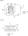
- the second pattern 28, observable under ultraviolet radiation 30, in reflection, is schematically illustrated by the figure 2b .
- the reflected ultraviolet radiation 30 is transmitted only by the perforations 20 having a dimension greater than or equal to the minimum dimension 32.
- These perforations 20 are shown in the figure 2b at the level of the hair 28a, the eyes 28b and the lips 28b.
- the perforations 20 of the cheeks and the forehead have a dimension smaller than that of the minimum dimension 32 and therefore do not allow the second reflected radiation 30 to pass.
- a document is thus obtained from which it is possible to observe a first pattern 24 under visible radiation 19, the visible radiation 19 passing through all the perforations 20 and to observe a second pattern 28 from the perforations 20 of the first pattern 24 whose dimensions are greater than or equal to the minimum dimension 32.
- the following manufacturing method will be implemented by the laser device emitting laser radiation and comprising a processing system.
- the method comprises a prior step of providing, on the laser device, an identity document comprising at least one window 16 comprising at least two transparent plastic layers 16a, 16b, a metal patch 18 and an ink layer 22 being sandwiched between the plastic layers 16a, 16b.
- the ink layer 22 is printed partially or totally opposite the metal patch 18, that is to say below the metal patch 18 when the document is observed in a direction perpendicular to its plane, and the ink layer 22 reacts, that is to say is excited, under the incidence of a second radiation 30 of wavelength shorter than that of the visible radiation 19.
- the laser device is adapted to perforate the metal patch 18.
- the processing system of the laser device is adapted to process data that will be used to control the positioning of the laser beam perforating the metal patch 18.
- the manufacturing method comprises a step of reception by the laser processing system of data relating to the first pattern 24. Then the processing system performs a step of decomposition of the first pattern 24 into gray level pixels, each gray level of the pixel corresponding to a dimension of at least one perforation in a perforation zone.
- the manufacturing method includes a step of determining the minimum dimension 32 of perforation allowing the second radiation 30 to pass.
- the value of the minimum dimension 32 can vary according to the observation conditions and the second radiation 30 chosen. It will be determined beforehand and transmitted to the processing system, or directly determined by the processing system, according to the observation conditions of the second pattern. 28.
- the second pattern 28 is considered to be observed in a direction perpendicular to the plane of the document, in reflection, under incidence of the second radiation 30.
- the second radiation 30 is ultraviolet radiation
- the minimum perforation dimension 32 allowing the ultraviolet radiation 30 to pass through has the shape of a disk with a diameter of 19 nm.
- the manufacturing method then comprises a step of assigning the minimum perforation dimension 32 to a pixel gray level of the first pattern 24.
- the assigned gray level is chosen from the 10% of the darkest gray levels.
- the minimum perforation dimension 32 is assigned to the darkest gray level in the gray color chart of the pixels.
- the processing system it is also possible to carry out, by the processing system, the replacement of a perforation dimension of a gray level among the 90% least dark by a minimum dimension 32, so as to form the second pattern 28 without however modifying the first pattern 24 observable under visible radiation 19. It is preferable in this case that the replaced perforations 20 are isolated, that is to say not neighboring, from the other perforations 20 of dimensions equal to or greater than the minimum dimensions so as not to modify the perception of the first observed pattern 24.
- the perforations 20 of dimensions equal to or greater than the minimum dimensions are thus dedicated to the formation of the second pattern 28 observable under specific conditions.
- the processing system receives data relating to the second pattern 28 intended to be formed by perforation of the metal patch 18 and intended to be observable under the second radiation 30.
- the processing system defines the position of the perforations 20 dedicated to the second pattern 28, these perforations 20 each having dimensions greater than or equal to the minimum dimensions.
- the processing system assigns the minimum perforation dimension 32 32 to a gray level of the pixel so as to visualize the second pattern 28 under the second radiation 30, in reflection and the first pattern 24 under visible radiation 19.
- the manufacturing method makes it possible to obtain an identity document 10 with two security patterns.
- the identity document 10 comprises a plastic body provided with a transparent window 16 formed from transparent plastic layers 16a, 16b between which the metal patch 18 and the ink sensitive to the second radiation 30 are positioned.
- the ink and the patch are arranged substantially opposite each other so as to obtain a superposition of the ink and the patch when observed perpendicular to the plane of the identity document 10.
- the metal patch 18 of the document is a thin metal sheet reflecting the incident light and the ink is excited under the second radiation. 30 incident, for example ultraviolet radiation.
- the patch and the ink have negligible thicknesses compared to the thicknesses of the plastic layers 16a, 16b constituting the window 16.
- the metal patch 18 and the ink layer 22 are positioned at the interface of two transparent layers, without deforming and creating excess thickness in the plastic layer.
- FIG. 4 illustrates an embodiment in which the metal patch 18 is positioned at the interface of the two transparent plastic layers 16a, 16b of the window 16, and the ink layer 22 is positioned below the interface layer of the patch 18.
- the ink 22 and the patch 18 are not in direct contact, but produce the technical effects described further in the description.
- FIG. 5 illustrates a more complex embodiment involving two metal patches 18a, 18b. It is thus possible to engrave the two patches 18a, 18b in order to secure the front face and the rear face of the window 16 by hiding information.
- the document described in the present invention is used in the context of a method for authenticating an identity document 10.
- This method is implemented by a step of positioning the window 16 of the document on an opaque background 17 blocking visible light, then reading/acquiring data from the identity document 10 under visible radiation 19. Then the document is illuminated under a second radiation 30, namely ultraviolet radiation on the face of the identity document so that the UV ink is positioned under the metal patch 18. It is then possible to acquire the second pattern 28 visible under UV radiation and to verify this second pattern 28 with a reference element, for example the first pattern 24. If the two patterns match, the verification is approved and the authentication of the document is validated.
Landscapes
- Health & Medical Sciences (AREA)
- General Health & Medical Sciences (AREA)
- Toxicology (AREA)
- Physics & Mathematics (AREA)
- General Physics & Mathematics (AREA)
- Electromagnetism (AREA)
- Optics & Photonics (AREA)
- Engineering & Computer Science (AREA)
- Manufacturing & Machinery (AREA)
- Credit Cards Or The Like (AREA)
- Laser Beam Processing (AREA)
Applications Claiming Priority (1)
| Application Number | Priority Date | Filing Date | Title |
|---|---|---|---|
| FR2306480A FR3150139B1 (fr) | 2023-06-22 | 2023-06-22 | Procédé de fabrication d’un document d’identité |
Publications (1)
| Publication Number | Publication Date |
|---|---|
| EP4480714A1 true EP4480714A1 (de) | 2024-12-25 |
Family
ID=88504694
Family Applications (1)
| Application Number | Title | Priority Date | Filing Date |
|---|---|---|---|
| EP24180691.8A Pending EP4480714A1 (de) | 2023-06-22 | 2024-06-07 | Verfahren zur herstellung einer sicherheitsvorrichtung mit mindestens einem ersten, unter einem ersten winkel sichtbaren bild und einem zweiten, unter einem zweiten winkel sichtbaren bild, durch das verfahren erhaltene sicherheitsvorrichtung und ein die sicherheitsvorrichtung enthaltendes identitätsdokument |
Country Status (2)
| Country | Link |
|---|---|
| EP (1) | EP4480714A1 (de) |
| FR (1) | FR3150139B1 (de) |
Citations (7)
| Publication number | Priority date | Publication date | Assignee | Title |
|---|---|---|---|---|
| EP0956975A2 (de) | 1994-03-25 | 1999-11-17 | Giesecke & Devrient GmbH | Vor unerlaubter Reprodukton mit einem Kopiergerät geschützte Ausweiskarte |
| WO2001007268A1 (en) | 1999-07-23 | 2001-02-01 | De La Rue International Limited | Security device |
| EP1983473A1 (de) * | 2003-11-12 | 2008-10-22 | Giesecke & Devrient GmbH | Datenträger mit Kennzeichnungen |
| EP2407314A1 (de) * | 2010-07-13 | 2012-01-18 | Oberthur Technologies | Verfahren zur Aufbringung eines Motivs auf eine Unterlage mit Hilfe von Sicherheitstinte |
| FR3045432A1 (fr) | 2015-12-17 | 2017-06-23 | Oberthur Technologies | Realisation d'une fenetre dans une couche en plastique mince |
| WO2018127269A2 (de) * | 2017-01-09 | 2018-07-12 | Giesecke+Devrient Currency Technology Gmbh | Sicherheitselement mit gelaserter oberfläche |
| EP3842254A1 (de) * | 2019-12-24 | 2021-06-30 | Thales Dis France Sa | Personalisierbares lumineszierendes sicherheitselement |
-
2023
- 2023-06-22 FR FR2306480A patent/FR3150139B1/fr active Active
-
2024
- 2024-06-07 EP EP24180691.8A patent/EP4480714A1/de active Pending
Patent Citations (7)
| Publication number | Priority date | Publication date | Assignee | Title |
|---|---|---|---|---|
| EP0956975A2 (de) | 1994-03-25 | 1999-11-17 | Giesecke & Devrient GmbH | Vor unerlaubter Reprodukton mit einem Kopiergerät geschützte Ausweiskarte |
| WO2001007268A1 (en) | 1999-07-23 | 2001-02-01 | De La Rue International Limited | Security device |
| EP1983473A1 (de) * | 2003-11-12 | 2008-10-22 | Giesecke & Devrient GmbH | Datenträger mit Kennzeichnungen |
| EP2407314A1 (de) * | 2010-07-13 | 2012-01-18 | Oberthur Technologies | Verfahren zur Aufbringung eines Motivs auf eine Unterlage mit Hilfe von Sicherheitstinte |
| FR3045432A1 (fr) | 2015-12-17 | 2017-06-23 | Oberthur Technologies | Realisation d'une fenetre dans une couche en plastique mince |
| WO2018127269A2 (de) * | 2017-01-09 | 2018-07-12 | Giesecke+Devrient Currency Technology Gmbh | Sicherheitselement mit gelaserter oberfläche |
| EP3842254A1 (de) * | 2019-12-24 | 2021-06-30 | Thales Dis France Sa | Personalisierbares lumineszierendes sicherheitselement |
Also Published As
| Publication number | Publication date |
|---|---|
| FR3150139B1 (fr) | 2025-06-27 |
| FR3150139A1 (fr) | 2024-12-27 |
Similar Documents
| Publication | Publication Date | Title |
|---|---|---|
| EP2750897B1 (de) | Sicherheitsstruktur mit einer reflektierenden optischen struktur und zugehöriges verfahren | |
| EP2780173B1 (de) | Mehrschichtige struktur, und sicherheitsdokument und echtheitsprüfung dazu | |
| EP3828000B1 (de) | Sicherheitsdokument und dessen herstellungsverfahren, die ein individuell gestaltes bild auf der basis eines metallhologramm betreffen | |
| FR2969670A1 (fr) | Element pour document de securite comportant une structure optique | |
| FR2945238A1 (fr) | Dispositif a effets optiques variables et document de securite incluant ledit dispositif | |
| CA2941531A1 (fr) | Document comprenant au moins deux images photoluminescentes, film de securite et procede de protection securitaire | |
| EP3194178B1 (de) | Sicherheitselement | |
| CA2816384C (fr) | Dispositif de securite optiquement variable pour un document-valeur | |
| EP4251430B1 (de) | Personalisiertes bild aus einer metallschicht und einem linsenraster | |
| EP2935696B1 (de) | Sicherheitsstruktur | |
| FR3003800A1 (fr) | Dispositif de securite a base de lentilles - feuille | |
| FR3150139A1 (fr) | Procédé de fabrication d’un document d’identité | |
| WO2013030782A1 (fr) | Structure de sécurité comportant un vernis transparent, et procédé associe | |
| FR2962684A1 (fr) | Procede de realisation d'un motif sur un support avec une encre de securite | |
| EP4283399A1 (de) | Verfahren zur herstellung eines identitätsdokuments, identitätsdokument und verfahren zur authentifizierung eines solchen identitätsdokuments | |
| WO2015087275A1 (fr) | Structure de sécurité | |
| EP3271192A1 (de) | Sicherheitselement und sicherheitsdokument | |
| EP4088946B1 (de) | Herstellung eines bilds aus einer holografischen struktur | |
| EP4663426A1 (de) | Verfahren zur herstellung eines identitätsdokuments | |
| EP4520543A1 (de) | Verfahren zur personalisierung eines sicheren dokuments | |
| EP4442471A1 (de) | Sicheres dokument und verfahren zur herstellung eines sicheren dokuments | |
| FR3141639A1 (fr) | Dispositif optique de sécurité | |
| FR3010000A1 (de) |
Legal Events
| Date | Code | Title | Description |
|---|---|---|---|
| PUAI | Public reference made under article 153(3) epc to a published international application that has entered the european phase |
Free format text: ORIGINAL CODE: 0009012 |
|
| STAA | Information on the status of an ep patent application or granted ep patent |
Free format text: STATUS: REQUEST FOR EXAMINATION WAS MADE |
|
| 17P | Request for examination filed |
Effective date: 20240607 |
|
| AK | Designated contracting states |
Kind code of ref document: A1 Designated state(s): AL AT BE BG CH CY CZ DE DK EE ES FI FR GB GR HR HU IE IS IT LI LT LU LV MC ME MK MT NL NO PL PT RO RS SE SI SK SM TR |
|
| RAP1 | Party data changed (applicant data changed or rights of an application transferred) |
Owner name: IDEMIA IDENTITY & SECURITY FRANCE |
|
| RAP3 | Party data changed (applicant data changed or rights of an application transferred) |
Owner name: IN SMART IDENTITY FRANCE |