EP4480767A1 - Bremssystem, steuerungsvorrichtung und elektrofahrzeug - Google Patents
Bremssystem, steuerungsvorrichtung und elektrofahrzeug Download PDFInfo
- Publication number
- EP4480767A1 EP4480767A1 EP24751358.3A EP24751358A EP4480767A1 EP 4480767 A1 EP4480767 A1 EP 4480767A1 EP 24751358 A EP24751358 A EP 24751358A EP 4480767 A1 EP4480767 A1 EP 4480767A1
- Authority
- EP
- European Patent Office
- Prior art keywords
- brake disc
- braking force
- braking
- control
- actuator
- Prior art date
- Legal status (The legal status is an assumption and is not a legal conclusion. Google has not performed a legal analysis and makes no representation as to the accuracy of the status listed.)
- Pending
Links
Images



Classifications
-
- B—PERFORMING OPERATIONS; TRANSPORTING
- B60—VEHICLES IN GENERAL
- B60T—VEHICLE BRAKE CONTROL SYSTEMS OR PARTS THEREOF; BRAKE CONTROL SYSTEMS OR PARTS THEREOF, IN GENERAL; ARRANGEMENT OF BRAKING ELEMENTS ON VEHICLES IN GENERAL; PORTABLE DEVICES FOR PREVENTING UNWANTED MOVEMENT OF VEHICLES; VEHICLE MODIFICATIONS TO FACILITATE COOLING OF BRAKES
- B60T8/00—Arrangements for adjusting wheel-braking force to meet varying vehicular or ground-surface conditions, e.g. limiting or varying distribution of braking force
- B60T8/26—Arrangements for adjusting wheel-braking force to meet varying vehicular or ground-surface conditions, e.g. limiting or varying distribution of braking force characterised by producing differential braking between front and rear wheels
-
- B—PERFORMING OPERATIONS; TRANSPORTING
- B60—VEHICLES IN GENERAL
- B60K—ARRANGEMENT OR MOUNTING OF PROPULSION UNITS OR OF TRANSMISSIONS IN VEHICLES; ARRANGEMENT OR MOUNTING OF PLURAL DIVERSE PRIME-MOVERS IN VEHICLES; AUXILIARY DRIVES FOR VEHICLES; INSTRUMENTATION OR DASHBOARDS FOR VEHICLES; ARRANGEMENTS IN CONNECTION WITH COOLING, AIR INTAKE, GAS EXHAUST OR FUEL SUPPLY OF PROPULSION UNITS IN VEHICLES
- B60K17/00—Arrangement or mounting of transmissions in vehicles
- B60K17/34—Arrangement or mounting of transmissions in vehicles for driving both front and rear wheels, e.g. four wheel drive vehicles
- B60K17/356—Arrangement or mounting of transmissions in vehicles for driving both front and rear wheels, e.g. four wheel drive vehicles having fluid or electric motor, for driving one or more wheels
-
- B—PERFORMING OPERATIONS; TRANSPORTING
- B60—VEHICLES IN GENERAL
- B60K—ARRANGEMENT OR MOUNTING OF PROPULSION UNITS OR OF TRANSMISSIONS IN VEHICLES; ARRANGEMENT OR MOUNTING OF PLURAL DIVERSE PRIME-MOVERS IN VEHICLES; AUXILIARY DRIVES FOR VEHICLES; INSTRUMENTATION OR DASHBOARDS FOR VEHICLES; ARRANGEMENTS IN CONNECTION WITH COOLING, AIR INTAKE, GAS EXHAUST OR FUEL SUPPLY OF PROPULSION UNITS IN VEHICLES
- B60K7/00—Disposition of motor in, or adjacent to, traction wheel
- B60K7/0007—Disposition of motor in, or adjacent to, traction wheel the motor being electric
-
- B—PERFORMING OPERATIONS; TRANSPORTING
- B60—VEHICLES IN GENERAL
- B60L—PROPULSION OF ELECTRICALLY-PROPELLED VEHICLES; SUPPLYING ELECTRIC POWER FOR AUXILIARY EQUIPMENT OF ELECTRICALLY-PROPELLED VEHICLES; ELECTRODYNAMIC BRAKE SYSTEMS FOR VEHICLES IN GENERAL; MAGNETIC SUSPENSION OR LEVITATION FOR VEHICLES; MONITORING OPERATING VARIABLES OF ELECTRICALLY-PROPELLED VEHICLES; ELECTRIC SAFETY DEVICES FOR ELECTRICALLY-PROPELLED VEHICLES
- B60L15/00—Methods, circuits, or devices for controlling the traction-motor speed of electrically-propelled vehicles
- B60L15/20—Methods, circuits, or devices for controlling the traction-motor speed of electrically-propelled vehicles for control of the vehicle or its driving motor to achieve a desired performance, e.g. speed, torque, programmed variation of speed
- B60L15/2009—Methods, circuits, or devices for controlling the traction-motor speed of electrically-propelled vehicles for control of the vehicle or its driving motor to achieve a desired performance, e.g. speed, torque, programmed variation of speed for braking
-
- B—PERFORMING OPERATIONS; TRANSPORTING
- B60—VEHICLES IN GENERAL
- B60L—PROPULSION OF ELECTRICALLY-PROPELLED VEHICLES; SUPPLYING ELECTRIC POWER FOR AUXILIARY EQUIPMENT OF ELECTRICALLY-PROPELLED VEHICLES; ELECTRODYNAMIC BRAKE SYSTEMS FOR VEHICLES IN GENERAL; MAGNETIC SUSPENSION OR LEVITATION FOR VEHICLES; MONITORING OPERATING VARIABLES OF ELECTRICALLY-PROPELLED VEHICLES; ELECTRIC SAFETY DEVICES FOR ELECTRICALLY-PROPELLED VEHICLES
- B60L7/00—Electrodynamic brake systems for vehicles in general
- B60L7/24—Electrodynamic brake systems for vehicles in general with additional mechanical or electromagnetic braking
- B60L7/26—Controlling the braking effect
-
- B—PERFORMING OPERATIONS; TRANSPORTING
- B60—VEHICLES IN GENERAL
- B60T—VEHICLE BRAKE CONTROL SYSTEMS OR PARTS THEREOF; BRAKE CONTROL SYSTEMS OR PARTS THEREOF, IN GENERAL; ARRANGEMENT OF BRAKING ELEMENTS ON VEHICLES IN GENERAL; PORTABLE DEVICES FOR PREVENTING UNWANTED MOVEMENT OF VEHICLES; VEHICLE MODIFICATIONS TO FACILITATE COOLING OF BRAKES
- B60T17/00—Component parts, details, or accessories of power brake systems not covered by groups B60T8/00, B60T13/00 or B60T15/00, or presenting other characteristic features
- B60T17/18—Safety devices; Monitoring
- B60T17/22—Devices for monitoring or checking brake systems; Signal devices
- B60T17/221—Procedure or apparatus for checking or keeping in a correct functioning condition of brake systems
-
- B—PERFORMING OPERATIONS; TRANSPORTING
- B60—VEHICLES IN GENERAL
- B60T—VEHICLE BRAKE CONTROL SYSTEMS OR PARTS THEREOF; BRAKE CONTROL SYSTEMS OR PARTS THEREOF, IN GENERAL; ARRANGEMENT OF BRAKING ELEMENTS ON VEHICLES IN GENERAL; PORTABLE DEVICES FOR PREVENTING UNWANTED MOVEMENT OF VEHICLES; VEHICLE MODIFICATIONS TO FACILITATE COOLING OF BRAKES
- B60T8/00—Arrangements for adjusting wheel-braking force to meet varying vehicular or ground-surface conditions, e.g. limiting or varying distribution of braking force
- B60T8/17—Using electrical or electronic regulation means to control braking
- B60T8/171—Detecting parameters used in the regulation; Measuring values used in the regulation
-
- B—PERFORMING OPERATIONS; TRANSPORTING
- B60—VEHICLES IN GENERAL
- B60T—VEHICLE BRAKE CONTROL SYSTEMS OR PARTS THEREOF; BRAKE CONTROL SYSTEMS OR PARTS THEREOF, IN GENERAL; ARRANGEMENT OF BRAKING ELEMENTS ON VEHICLES IN GENERAL; PORTABLE DEVICES FOR PREVENTING UNWANTED MOVEMENT OF VEHICLES; VEHICLE MODIFICATIONS TO FACILITATE COOLING OF BRAKES
- B60T8/00—Arrangements for adjusting wheel-braking force to meet varying vehicular or ground-surface conditions, e.g. limiting or varying distribution of braking force
- B60T8/17—Using electrical or electronic regulation means to control braking
- B60T8/172—Determining control parameters used in the regulation, e.g. by calculations involving measured or detected parameters
-
- B—PERFORMING OPERATIONS; TRANSPORTING
- B60—VEHICLES IN GENERAL
- B60K—ARRANGEMENT OR MOUNTING OF PROPULSION UNITS OR OF TRANSMISSIONS IN VEHICLES; ARRANGEMENT OR MOUNTING OF PLURAL DIVERSE PRIME-MOVERS IN VEHICLES; AUXILIARY DRIVES FOR VEHICLES; INSTRUMENTATION OR DASHBOARDS FOR VEHICLES; ARRANGEMENTS IN CONNECTION WITH COOLING, AIR INTAKE, GAS EXHAUST OR FUEL SUPPLY OF PROPULSION UNITS IN VEHICLES
- B60K17/00—Arrangement or mounting of transmissions in vehicles
- B60K17/34—Arrangement or mounting of transmissions in vehicles for driving both front and rear wheels, e.g. four wheel drive vehicles
- B60K17/354—Arrangement or mounting of transmissions in vehicles for driving both front and rear wheels, e.g. four wheel drive vehicles having separate mechanical assemblies for transmitting drive to the front or to the rear wheels or set of wheels
-
- B—PERFORMING OPERATIONS; TRANSPORTING
- B60—VEHICLES IN GENERAL
- B60L—PROPULSION OF ELECTRICALLY-PROPELLED VEHICLES; SUPPLYING ELECTRIC POWER FOR AUXILIARY EQUIPMENT OF ELECTRICALLY-PROPELLED VEHICLES; ELECTRODYNAMIC BRAKE SYSTEMS FOR VEHICLES IN GENERAL; MAGNETIC SUSPENSION OR LEVITATION FOR VEHICLES; MONITORING OPERATING VARIABLES OF ELECTRICALLY-PROPELLED VEHICLES; ELECTRIC SAFETY DEVICES FOR ELECTRICALLY-PROPELLED VEHICLES
- B60L2240/00—Control parameters of input or output; Target parameters
- B60L2240/10—Vehicle control parameters
- B60L2240/36—Temperature of vehicle components or parts
-
- B—PERFORMING OPERATIONS; TRANSPORTING
- B60—VEHICLES IN GENERAL
- B60L—PROPULSION OF ELECTRICALLY-PROPELLED VEHICLES; SUPPLYING ELECTRIC POWER FOR AUXILIARY EQUIPMENT OF ELECTRICALLY-PROPELLED VEHICLES; ELECTRODYNAMIC BRAKE SYSTEMS FOR VEHICLES IN GENERAL; MAGNETIC SUSPENSION OR LEVITATION FOR VEHICLES; MONITORING OPERATING VARIABLES OF ELECTRICALLY-PROPELLED VEHICLES; ELECTRIC SAFETY DEVICES FOR ELECTRICALLY-PROPELLED VEHICLES
- B60L2260/00—Operating Modes
- B60L2260/20—Drive modes; Transition between modes
- B60L2260/28—Four wheel or all wheel drive
-
- B—PERFORMING OPERATIONS; TRANSPORTING
- B60—VEHICLES IN GENERAL
- B60T—VEHICLE BRAKE CONTROL SYSTEMS OR PARTS THEREOF; BRAKE CONTROL SYSTEMS OR PARTS THEREOF, IN GENERAL; ARRANGEMENT OF BRAKING ELEMENTS ON VEHICLES IN GENERAL; PORTABLE DEVICES FOR PREVENTING UNWANTED MOVEMENT OF VEHICLES; VEHICLE MODIFICATIONS TO FACILITATE COOLING OF BRAKES
- B60T2270/00—Further aspects of brake control systems not otherwise provided for
- B60T2270/60—Regenerative braking
- B60T2270/604—Merging friction therewith; Adjusting their repartition
-
- Y—GENERAL TAGGING OF NEW TECHNOLOGICAL DEVELOPMENTS; GENERAL TAGGING OF CROSS-SECTIONAL TECHNOLOGIES SPANNING OVER SEVERAL SECTIONS OF THE IPC; TECHNICAL SUBJECTS COVERED BY FORMER USPC CROSS-REFERENCE ART COLLECTIONS [XRACs] AND DIGESTS
- Y02—TECHNOLOGIES OR APPLICATIONS FOR MITIGATION OR ADAPTATION AGAINST CLIMATE CHANGE
- Y02T—CLIMATE CHANGE MITIGATION TECHNOLOGIES RELATED TO TRANSPORTATION
- Y02T10/00—Road transport of goods or passengers
- Y02T10/60—Other road transportation technologies with climate change mitigation effect
- Y02T10/72—Electric energy management in electromobility
Definitions
- This application relates to the field of braking systems of electric vehicles, and in particular, to a braking system, a control apparatus, and an electric vehicle.
- Braking performance of an electric vehicle greatly affects safety and comfort of the electric vehicle.
- braking methods of the electric vehicle mainly include friction braking and feedback braking.
- the friction braking means that a braking system of the electric vehicle directly outputs braking force
- the feedback braking means that a drive motor of the electric vehicle is in a power generation state and outputs braking force to a wheel of the electric vehicle during braking of the electric vehicle.
- Cooperation between the feedback braking and mechanical braking is a hot issue of concern.
- a temperature of a brake disc of the braking system of the electric vehicle greatly affects reliability and braking performance of the braking system. If the temperature of the brake disc is too high or too low, the braking performance of the braking system deteriorates, and running life is shortened.
- this application provides a braking system, a control apparatus, and an electric vehicle.
- this application provides a braking system for an electric vehicle.
- the braking system includes a controller and four actuators.
- Each actuator includes a brake disc, four brake discs include two front brake discs and two rear brake discs, the two front brake discs include a left front brake disc and a right front brake disc, and the two rear brake discs include a left rear brake disc and a right rear brake disc.
- the controller is configured to receive a braking signal of the braking system and output four control signals.
- the braking signal of the braking system indicates total braking force of the braking system, and the four control signals are respectively used to control the four actuators to output braking force.
- the braking system is configured to adjust, based on temperatures of the four brake discs, the braking force output by the four actuators.
- the four control signals are used to control an actuator corresponding to a brake disc whose temperature is less than or equal to a first preset value to increase braking force output, where a sum of the braking force output by the four actuators is equal to the total braking force indicated by the braking signal of the braking system.
- the four control signals are used to control an actuator corresponding to a brake disc whose temperature is greater than or equal to a second preset value to reduce braking force output, where a sum of the braking force output by the four actuators is equal to the total braking force indicated by the braking signal of the braking system.
- the braking system provided in the application can adjust the braking force output of the actuator based on the temperature of the brake disc. If a brake disc is overheated, braking force output of an actuator corresponding to the brake disc is reduced. In this case, friction on the overheated brake disc is reduced, and a temperature rise speed of the brake disc is slowed down. If a temperature of a brake disc is too low, braking force output corresponding to the brake disc is increased. In this case, friction on the brake disc with the too low temperature is increased, and the temperature of the brake disc rapidly increases.
- the braking system provided in this application can prevent the temperature of the brake disc from being too low or too high by controlling the friction on the brake disc, to improve braking performance of the electric vehicle and service life and reliability of the brake disc.
- actuators corresponding to the two front brake discs are front actuators.
- the controller outputs the four control signals to increase braking force output of the front actuator in response to a temperature of at least one front brake disc being less than or equal to the first preset value.
- the controller outputs the four control signals to reduce braking force output of the front actuator in response to a temperature of at least one front brake disc being greater than or equal to the second preset value.
- actuators corresponding to the two rear brake discs are rear actuators.
- the controller outputs the four control signals to control the rear actuator to increase the braking force output in response to a temperature of at least one rear brake disc being less than or equal to the first preset value.
- the controller outputs the four control signals to control the rear actuator to reduce the braking force output in response to a temperature of at least one rear brake disc being greater than or equal to the second preset value.
- the left front brake disc and the right rear brake disc respectively correspond to a left front actuator and a right rear actuator.
- the controller is configured to control the left front actuator and the right rear actuator to increase the braking force output in response to a temperature of the left front brake disc or the right rear brake disc being less than or equal to the first preset value.
- the controller outputs the four control signals to control the left front actuator and the right rear actuator to reduce the braking force output in response to a temperature of the right front brake disc or the left rear brake disc being greater than or equal to the second preset value.
- the right front brake disc and the left rear brake disc respectively correspond to a right front actuator and a left rear actuator.
- the controller outputs the four control signals to control the right front actuator and the left rear actuator to increase the braking force output in response to the temperature of the right front brake disc or the left rear brake disc being less than or equal to the first preset value.
- the controller outputs the four control signals to control the right front actuator and the left rear actuator to reduce the braking force output in response to the temperature of the right front brake disc or the left rear brake disc being less than or equal to the second preset value.
- the braking system When braking force output by one actuator of the braking system suddenly change, the braking force output by the four actuators of the electric vehicle is different in magnitude. In this case, a vehicle body of the electric vehicle is unstable, and the electric vehicle has a risk of slipping and rollover. Therefore, when the temperature of the brake disc of the electric vehicle is abnormal, the braking system provided in this application simultaneously changes braking force output by two front actuators, or simultaneously changes braking force output by two rear actuators, or simultaneously changes braking force output by two diagonal actuators, to improve stability of the vehicle body of the electric vehicle in a braking process.
- this application provides a control apparatus for an electric vehicle.
- the electric vehicle includes a drive system, and the drive system includes at least one drive motor and at least one motor controller.
- the motor controller is configured to control the drive motor to output driving force in response to the electric vehicle running in a driving state.
- the motor controller is configured to control the drive motor to output braking force to a wheel connected to the drive motor in response to the electric vehicle running in a braking state.
- the electric vehicle includes a braking system, the braking system includes four actuators, each actuator includes a brake disc, the four actuators are configured to output the braking force, four brake discs include two front brake discs and two rear brake discs, the two front brake discs include a left front brake disc and a right front brake disc, and the two rear brake discs include a left rear brake disc and a right rear brake disc.
- the control apparatus outputs a control signal of the drive system to control the drive system to reduce braking force output in response to a temperature of a brake disc corresponding to at least one wheel connected to the drive motor being less than or equal to a first preset value.
- the motor controller is configured to receive the control signal of the drive system and control the drive motor to reduce the braking force output.
- the control apparatus outputs a control signal of the drive system to control the drive system to increase braking force output in response to a temperature of a brake disc corresponding to at least one wheel connected to the drive motor being greater than or equal to a second preset value.
- the motor controller is configured to receive the control signal of the drive system and control the drive motor to increase the braking force output.
- the drive system includes a front-drive motor, and the front-drive motor is connected to two front wheels of the electric vehicle.
- the control apparatus controls the drive system to reduce the braking force output in response to a temperature of at least one front brake disc being less than or equal to the first preset value; or the control apparatus controls the drive system to increase the braking force output in response to a temperature of at least one front brake disc being greater than or equal to the second preset value.
- the drive system includes a rear-drive motor, and the rear-drive motor is connected to two rear wheels of the electric vehicle.
- the control apparatus controls the drive system to reduce the braking force output in response to a temperature of at least one rear brake disc being less than or equal to the first preset value; or the control apparatus controls the drive system to increase the braking force output in response to a temperature of at least one rear brake disc being greater than or equal to the second preset value.
- the drive system includes four drive motors, and the four drive motors are respectively connected to four wheels of the electric vehicle.
- the control apparatus is configured to control the drive system connected to the wheel corresponding to the brake disc whose temperature is less than or equal to the first preset value to reduce the braking force output; or the control apparatus is configured to control the drive system connected to the wheel corresponding to the brake disc whose temperature is greater than or equal to the second preset value to increase the braking force output.
- the control apparatus is configured to receive a vehicle braking signal and output a control signal of the braking system, the vehicle braking signal indicates total braking force output by the drive system and the braking system, the control signal of the braking system includes four actuator control signals, and the four actuator control signals are respectively used to control the four actuators to output the braking force.
- the control apparatus is configured to adjust, based on temperatures of the four brake discs when the electric vehicle runs in the braking state, braking force output by the drive system and the braking system. A sum of the braking force output by the drive system and the braking system is equal to the total braking force indicated by the vehicle braking signal.
- the control apparatus controls the braking force output of the drive system by outputting the control signal of the drive system.
- the temperature of the brake disc corresponding to the wheel connected to the drive motor is too high, the braking force output by the drive system is increased.
- the sum of the braking force output by the drive system and the braking system is specific, the braking force output by the braking system is reduced, friction on the brake disc of the electric vehicle is also reduced, and a temperature rise speed of the brake disc is reduced. This prevents a problem like braking performance deterioration of the braking system caused by a too high temperature of the brake disc.
- the control apparatus provided in this embodiment of this application can improve the braking performance of the electric vehicle, and improve service life and reliability of the brake disc.
- actuators corresponding to the two front brake discs are front actuators.
- the control apparatus controls the front actuator to increase the braking force output in response to the temperature of the at least one front brake disc being less than or equal to the first preset value; or the control apparatus controls the front actuator to reduce the braking force output in response to the temperature of the at least one front brake disc being greater than or equal to the second preset value.
- actuators corresponding to the two rear brake discs are rear actuators.
- the control apparatus controls the rear actuator to increase the braking force output in response to the temperature of the at least one rear brake disc being less than or equal to the first preset value; or the control apparatus controls the rear actuator to reduce the braking force output in response to the temperature of the at least one rear brake disc being greater than or equal to the second preset value.
- control apparatus is configured to control an actuator corresponding to the brake disc whose temperature is less than or equal to the first preset value to increase the braking force output; or the control apparatus is configured to control an actuator corresponding to the brake disc whose temperature is greater than or equal to the second preset value to reduce the braking force output.
- the right front brake disc and the left rear brake disc respectively correspond to a right front actuator and a left rear actuator.
- the control apparatus is configured to control the right front actuator and the left rear actuator to increase the braking force output in response to a temperature of the right front brake disc or the left rear brake disc being less than or equal to the first preset value; or the control apparatus is configured to control the right front actuator and the left rear actuator to reduce the braking force output in response to a temperature of the right front brake disc or the left rear brake disc being less than or equal to the second preset value.
- the control apparatus provided in this application can adjust the braking force output of the actuator based on the temperature of the brake disc. If a brake disc is overheated, the control apparatus controls the actuator corresponding to the brake disc to reduce the braking force output. In this case, friction on the overheated brake disc is reduced, and a temperature rise speed of the brake disc is slowed down. If a temperature of a brake disc is too low, the control apparatus controls the an actuator corresponding to the brake disc increase the braking force output. In this case, friction on the brake disc with the too low temperature is increased, and the temperature of the brake disc rapidly increases.
- the braking system provided in this application can prevent the temperature of the brake disc from being too low or too high by controlling the friction on the brake disc, to improve braking performance of the electric vehicle and service life and reliability of the brake disc.
- this application provides an electric vehicle.
- the electric vehicle includes the braking system according to the first aspect or includes the control apparatus according to the second aspect.
- Beneficial effect of the electric vehicle provided in the third aspect of this application is beneficial effect of the braking system provided in the first aspect of this application or beneficial effect of the control apparatus provided in the second aspect of this application. Details are not described herein again.
- first, second, third, or the like or similar terms such as a module A, a module B, and a module C in the specification and claims are only used to distinguish between similar objects, and do not represent a specific order for objects. It can be understood that a specific order or sequence may be exchanged if allowed, so that embodiments of this application described herein can be implemented in an order other than that illustrated or described herein.
- One embodiment or “an embodiment” mentioned in this specification means that a specific feature, structure, or characteristic described in combination with this embodiment is included in at least one embodiment of this application. Therefore, the term “in one embodiment” or “in an embodiment” appearing throughout this specification does not necessarily refer to a same embodiment, but may refer to a same embodiment. Further, in one or more embodiments, the particular features, structures, or characteristics can be combined in any suitable manner, as will be apparent to a person of ordinary skill in the art from the present disclosure.
- the braking system provides braking force for a wheel of an electric vehicle.
- the braking system of the electric vehicle includes an electro-mechanical braking system and an electro-hydraulic braking system.
- a drive system of the electric vehicle is configured to: when the electric vehicle runs in a driving state, provide driving force for the electric vehicle; or when the electric vehicle runs in a braking state, convert kinetic energy of the electric vehicle into electric energy to charge a power battery, and provide braking force for the electric vehicle.
- the drive system of the electric vehicle includes a drive motor and a motor controller.
- the drive motor is in transmission connection with the wheel of the electric vehicle through a transmission apparatus.
- the drive system is configured to convert kinetic energy of the electric vehicle into electric energy, and torque output by the drive motor is transferred to the wheel through the transmission apparatus, to drive the wheel to run.
- the drive system When the electric vehicle is in a braking state, the drive system is configured to convert kinetic energy of the electric vehicle into electric energy.
- the drive motor runs in a power generation mode, and the drive motor absorbs kinetic energy of the wheel to generate power.
- the motor controller converts an alternating current generated by the drive motor into a direct current to charge the power battery of the electric vehicle.
- the braking system and the drive system cooperate with each other to provide the braking force for the wheel of the electric vehicle.
- the friction coefficient of the brake disc is reduced, thereby affecting braking effect and braking accuracy of the braking system.
- too high or too low temperature of the brake disc has great negative impact on service life and reliability of the brake disc itself.
- thermal attenuation of the braking system refers to a phenomenon that braking force of the braking system is attenuated after a high temperature is generated due to strong friction between the brake disc and a brake pad.
- the braking performance of the braking system in a high heat condition is greatly weakened. If the temperature exceeds the limit, a braking failure occurs.
- the temperature of the brake disc is directly related to the braking force of the braking system on the brake disc. Greater braking force of the braking system on the brake disc enables greater friction on the brake disc, and higher heat production efficiency of work done by the friction in the braking process enables a faster temperature rise speed of the brake disc. Greater braking force of the braking system on the brake disc enables smaller friction on the brake disc, and less heat production of work done by the friction in the braking process enables a slower temperature rise speed of the brake disc.
- embodiments of this application provide a braking system, a control apparatus, and an electric vehicle.
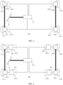
- FIG. 2 is a schematic diagram of an electric vehicle 10 according to an embodiment of this application.
- the electric vehicle 10 includes a braking system 20, a drive system 30, and a control apparatus 40.
- the braking system 20 and the drive system 30 are configured to output braking force when the electric vehicle 10 runs in a braking state.
- the electric vehicle 10 includes a wheel 11, and the wheel 11 includes a front wheel 111 and a rear wheel 112.
- the front wheel 111 includes a left front wheel 1111 and a right front wheel 1112
- the rear wheel 112 includes a left rear wheel 1121 and a right rear wheel 1122.
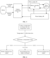
- FIG. 3 is a schematic diagram of a braking system according to an embodiment of this application.
- the braking system 20 includes a controller 22 and four actuators 23, and each actuator includes a brake disc 25.
- the controller 22 is configured to receive a braking signal 50 of the braking system and output four control signals 60.
- the braking signal 50 of the braking system indicates total braking force of the braking system, and the four control signals 60 are respectively used to control the four actuators 23 to output braking force.
- Four brake discs 25 include two front brake discs 251 and two rear brake discs 252, the two front brake discs 251 include a left front brake disc 2511 and a right front brake disc 2512, and the two rear brake discs 25 include a left rear brake disc 2521 and a right rear brake disc 2522.
- Actuators corresponding to the left front brake disc 2511, the right front brake disc 2512, the left rear brake disc 2521, and the right rear brake disc 2522 are respectively a left front actuator 2311, a right front actuator 2312, a left rear actuator 2321, and a right rear actuator 2322.
- the left front actuator 2311 and the right front actuator 2312 form a front actuator 231
- the left rear actuator 2321 and the right rear actuator 2322 form a rear actuator 232.
- the braking system 20 is an electro-hydraulic brake-by-wire system (EHB).
- the controller 22 is an electronic control unit (ECU) 221, and each actuator 23 includes a brake slave cylinder 232 and a brake 234.
- the electronic control unit (ECU) 221 receives the braking signal 50 of the braking system and outputs the four control signals 60.
- the four control signals 60 are used to control the four actuators 23 to output braking force.
- the braking system 20 is an electro-mechanical braking system (EMB).
- the controller 22 is an electronic control unit (ECU), and each actuator 23 includes a brake motor 235, a brake motor controller 236, and a brake 234.
- the electronic control unit (ECU) 222 receives the braking signal 50 of the braking system, and the electronic control unit (ECU) 221 controls, based on the braking signal of the braking system and a temperature of the brake disc 12, a voltage of a control current output by four brake motor controllers 236, to control the four brake motors 235 to apply different braking force to the four brake discs 12.
- the braking system 20 includes a sensor module 26, a brake pedal 27, and a pedal simulator 28.
- the sensor module 26 includes a temperature sensor, a vehicle speed sensor, and a pedal travel sensor.
- the pedal simulator 28 is configured to generate the braking signal 50 of the braking system based on a sensor signal from the sensor module 26.
- the braking signal 50 of the braking system indicates total braking force needed for braking of the electric vehicle.
- the drive motor 31 When the electric vehicle is in a driving state, the drive motor 31 is configured to provide driving force for the electric vehicle 10. Specifically, the drive motor 31 receives power supply of the power battery 40 of the electric vehicle 10 through the motor controller 32, and outputs torque to drive the electric vehicle 10. When the electric vehicle 10 is in a braking state, the drive motor 31 is configured to provide braking force for the electric vehicle 10. Specifically, the drive motor 31 runs in a power generation state, the drive motor 31 converts kinetic energy of the wheel 11 of the electric vehicle into electric energy, and outputs reverse torque to the wheel 11 of the electric vehicle 10, to provide the braking force for the electric vehicle 10.
- the drive system 30 keeps braking force output unchanged in response to a temperature of a brake disc 25 corresponding to at least one wheel 11 connected to the drive motor 31 being greater than the first preset value and the temperature of the brake disc 25 corresponding to the at least one wheel 11 connected to the drive motor 31 being less than the second preset value.
- the drive system 30 increases braking force output in response to a temperature of a brake disc 25 corresponding to at least one wheel 11 connected to the drive motor 31 being greater than or equal to the second preset value.
- the electric vehicle 10 is a rear-drive electric vehicle
- the drive system 30 includes a rear-drive motor 312.
- the rear-drive motor 312 When the electric vehicle 10 is in a driving state, the rear-drive motor 312 is configured to provide driving force for the two rear wheels 112 of the electric vehicle 10.
- the rear-drive motor 312 When the electric vehicle 10 is in a braking state, the rear-drive motor 312 is configured to provide braking force for the two rear wheels 112 of the electric vehicle 10.
- the electric vehicle 10 is a four-drive electric vehicle
- the drive system 30 includes a front-drive motor 311 and a rear-drive motor 312.
- the front-drive motor 311 is configured to provide driving force for the two front wheels 111 of the electric vehicle 10
- the rear-drive motor 312 is configured to provide driving force for the two rear wheels 112 of the electric vehicle 10.
- the front-drive motor 311 is configured to provide braking force for the two front wheels 111 of the electric vehicle 10
- the rear-drive motor 312 is configured to provide braking force for the two rear wheels 112 of the electric vehicle 10.
- the drive system 30 is a distributed drive system.
- the drive system 30 includes four drive motors 31.
- the four drive motors 31 When the electric vehicle 10 is in a driving state, the four drive motors 31 respectively provide driving force for the four wheels 11 of the electric vehicle 10.
- the four drive motors 31 When the electric vehicle 10 is in a braking state, the four drive motors 31 respectively provide braking force for the four wheels 11 of the electric vehicle 10.
- the braking system 20 is configured to adjust, based on temperatures of the four brake discs 25, braking force output by the four actuators 23.
- the controller 22 is configured to output four control signals to control an actuator 23 corresponding to the brake disc 25 whose temperature is less than or equal to the first preset value to increase the braking force output, where a sum of the braking force output by the four actuators 23 is equal to total braking force indicated by the braking signal 50 of the braking system.
- the controller 22 adjusts, based on the temperatures of the four brake discs 25, the four output control signals 60 to control the braking force output by the four actuators 23.
- the four control signals 60 are used to control the four actuators 23 to increase the braking force output of the actuator 23 corresponding to the brake disc 25 whose temperature is less than or equal to the first preset value, or the four control signals 60 are used to control the actuator 23 corresponding to the brake disc 25 whose temperature is greater than or equal to the second preset value to reduce the braking force output.
- a first preset temperature is 0 degrees Celsius. If a temperature of the left rear brake disc 2522 is -20 degrees Celsius in a braking process of the electric vehicle 10, the control signal 60 is used to increase the braking force output of the rear actuator 232.
- a second preset temperature is 300 degrees Celsius. If a temperature of the left rear brake disc 2521 is degrees Celsius in a braking process of the electric vehicle 10, the controller 22 is configured to reduce the braking force output of the rear actuator 232.
- the controller 22 when the temperature of the at least one front brake disc 251 is greater than a second preset temperature and the temperature of the at least one rear brake disc 252 is greater than or equal to the second preset temperature, the controller 22 is configured to reduce the braking force output of the front actuator 231 in response to an average temperature of the front brake disc 251 being greater than or equal to an average temperature of the rear brake disc 252; or the controller 22 is configured to reduce the braking force output of the rear actuator 232 in response to an average temperature of the front brake disc 251 being less than an average temperature of the rear brake disc 252.
- the braking system 20 When braking force output by one actuator of the braking system 20 suddenly change, the braking force output by the four actuators of the electric vehicle 10 is different in magnitude. In this case, a vehicle body of the electric vehicle 10 is unstable, and the electric vehicle 10 has a risk of slipping and rollover. Therefore, the braking system 20 provided in this embodiment simultaneously changes braking force output by two front actuators 231 or simultaneously changes braking force output by two rear actuators 232, to improve stability of the vehicle body of the electric vehicle 10 in a braking process.
- the drive system 30 is a distributed drive system.
- the drive system 30 includes four drive motors 31.
- the four drive motors 31 are respectively connected to four wheels of the electric vehicle.
- the control apparatus 40 is configured to: when the electric vehicle 10 is in a braking state, control the drive system 30 to reduce braking force output of a drive motor 31 connected to a wheel 11 corresponding to a brake disc 25 whose temperature is less than or equal to the first preset value.
- the control apparatus 40 is configured to: when the electric vehicle 10 is in a braking state, control the drive system 30 to increase braking force output of a drive motor 31 connected to a wheel 11 corresponding to a brake disc 25 whose temperature is greater than or equal to the second preset value.
- the control apparatus 40 provided in this embodiment of this application controls the braking force output of the drive system by outputting the control signal 70 of the drive system.
- the temperature of the brake disc corresponding to the wheel connected to the drive system 30 is too high, the braking force output by the drive system is increased.
- the braking force of the braking system 20 is reduced, friction on the brake disc 25 of the electric vehicle is also reduced, and a temperature rise speed of the brake disc 25 is reduced. This prevents a problem like braking performance deterioration of the braking system 20 caused by a too high temperature of the brake disc.
- control apparatus 40 controls a rear actuator 232 to increase the braking force output in response to the temperature of the at least one rear brake disc 252 being less than or equal to the first preset value. In an embodiment, the control apparatus 40 controls a rear actuator 232 to reduce the braking force output in response to the temperature of the at least one rear brake disc 252 being greater than or equal to the second preset value.
- control apparatus 40 is integrated in the vehicle control unit 51.
- control apparatus 40 is an electronic control unit (ECU) integrated in the braking system.
- ECU electronice control unit
Landscapes
- Engineering & Computer Science (AREA)
- Transportation (AREA)
- Mechanical Engineering (AREA)
- Power Engineering (AREA)
- Chemical & Material Sciences (AREA)
- Combustion & Propulsion (AREA)
- Physics & Mathematics (AREA)
- Electromagnetism (AREA)
- Regulating Braking Force (AREA)
- Braking Systems And Boosters (AREA)
- Electric Propulsion And Braking For Vehicles (AREA)
Applications Claiming Priority (2)
| Application Number | Priority Date | Filing Date | Title |
|---|---|---|---|
| CN202310495117.0A CN116442967A (zh) | 2023-05-05 | 2023-05-05 | 一种制动系统、控制装置及电动汽车 |
| PCT/CN2024/071214 WO2024230224A1 (zh) | 2023-05-05 | 2024-01-08 | 一种制动系统、控制装置及电动汽车 |
Publications (2)
| Publication Number | Publication Date |
|---|---|
| EP4480767A1 true EP4480767A1 (de) | 2024-12-25 |
| EP4480767A4 EP4480767A4 (de) | 2025-08-20 |
Family
ID=87127356
Family Applications (1)
| Application Number | Title | Priority Date | Filing Date |
|---|---|---|---|
| EP24751358.3A Pending EP4480767A4 (de) | 2023-05-05 | 2024-01-08 | Bremssystem, steuerungsvorrichtung und elektrofahrzeug |
Country Status (4)
| Country | Link |
|---|---|
| US (1) | US20240425024A1 (de) |
| EP (1) | EP4480767A4 (de) |
| CN (1) | CN116442967A (de) |
| WO (1) | WO2024230224A1 (de) |
Families Citing this family (3)
| Publication number | Priority date | Publication date | Assignee | Title |
|---|---|---|---|---|
| CN112924195A (zh) * | 2021-04-01 | 2021-06-08 | 中信戴卡股份有限公司 | 一种用于车轮及悬架系统试验的制动装置及实验设备 |
| CN116442967A (zh) * | 2023-05-05 | 2023-07-18 | 华为数字能源技术有限公司 | 一种制动系统、控制装置及电动汽车 |
| CN120573069A (zh) * | 2024-05-11 | 2025-09-02 | 小米汽车科技有限公司 | 制动力控制方法、装置、介质、产品及车辆 |
Family Cites Families (11)
| Publication number | Priority date | Publication date | Assignee | Title |
|---|---|---|---|---|
| DE10219067A1 (de) * | 2002-04-29 | 2003-11-20 | Wabco Gmbh & Co Ohg | Verfahren und Anordnung zur Zuspannenergieregelung bei elektronisch geregelten Bremssystemen von Fahrzeugen |
| US8596390B2 (en) * | 2007-12-05 | 2013-12-03 | Ford Global Technologies, Llc | Torque control for hybrid electric vehicle speed control operation |
| JP5116519B2 (ja) * | 2008-03-13 | 2013-01-09 | 日立オートモティブシステムズ株式会社 | 車両のブレーキ制御装置 |
| US8380418B2 (en) * | 2009-08-26 | 2013-02-19 | GM Global Technology Operations LLC | Method for maintaining a brake rotor |
| CN102612612B (zh) * | 2009-11-09 | 2015-04-29 | 丰田自动车株式会社 | 车辆的制动装置 |
| CN104590219B (zh) * | 2014-12-24 | 2019-07-12 | 阜阳市风雅颂生产力促进中心有限责任公司 | 一种防高温汽车刹车系统及其控制方法 |
| CN107303820B (zh) * | 2016-04-25 | 2019-06-28 | 上海汽车集团股份有限公司 | 防抱死制动系统及其控制方法、装置 |
| CN107554505B (zh) * | 2016-06-28 | 2021-05-18 | 罗伯特·博世有限公司 | 机动车辆用陡坡缓降方法及系统 |
| CN108045362B (zh) * | 2017-12-08 | 2020-05-12 | 毕作亮 | 刹车盘预热式制动方法 |
| CN110588615A (zh) * | 2019-08-28 | 2019-12-20 | 安徽理工大学 | 一种基于电子机械制动集成系统协调控制策略 |
| CN116442967A (zh) * | 2023-05-05 | 2023-07-18 | 华为数字能源技术有限公司 | 一种制动系统、控制装置及电动汽车 |
-
2023
- 2023-05-05 CN CN202310495117.0A patent/CN116442967A/zh active Pending
-
2024
- 2024-01-08 EP EP24751358.3A patent/EP4480767A4/de active Pending
- 2024-01-08 WO PCT/CN2024/071214 patent/WO2024230224A1/zh not_active Ceased
- 2024-09-06 US US18/826,631 patent/US20240425024A1/en active Pending
Also Published As
| Publication number | Publication date |
|---|---|
| WO2024230224A1 (zh) | 2024-11-14 |
| US20240425024A1 (en) | 2024-12-26 |
| EP4480767A4 (de) | 2025-08-20 |
| CN116442967A (zh) | 2023-07-18 |
Similar Documents
| Publication | Publication Date | Title |
|---|---|---|
| EP4480767A1 (de) | Bremssystem, steuerungsvorrichtung und elektrofahrzeug | |
| US5839800A (en) | Braking control system for electric automobile | |
| EP2789516B1 (de) | Fahrzeugsteuerungsvorrichtung | |
| JP5721792B2 (ja) | 少なくとも1つの電気モータを含む車両の回生制動制御方法 | |
| US8360533B2 (en) | Regenerative braking system | |
| JP5970953B2 (ja) | 車両用ブレーキ制御装置、車両用ブレーキ制御方法 | |
| KR101262973B1 (ko) | 하이브리드 전기 차량의 비상주행 제어시스템 및 그 제어방법 | |
| CN102582448B (zh) | 动力系中的混合制动管理 | |
| US20220097700A1 (en) | One-pedal drive filters and rate limits of powertrain torque | |
| US11634138B2 (en) | Electric vehicle | |
| KR20120024001A (ko) | 전기자동차의 제동 제어 방법 | |
| JP2007137413A (ja) | 回生ブレーキ装置を持つ車両、その車両の制御方法、回生ブレーキ装置を制御する方法、及びその方法をコンピューターに実行させるコンピューター・プログラム | |
| KR102883162B1 (ko) | 전동식 브레이크 장치 및 제어방법 | |
| CN111251898A (zh) | 复合制动系统的控制方法、装置和电动汽车 | |
| CN105437983A (zh) | 用于调整抬升踏板再生的车辆系统和方法 | |
| KR20110033620A (ko) | 회생 제동 시스템 | |
| CN112550254A (zh) | 电子机械制动系统及其控制方法 | |
| CN117734652A (zh) | 用于车辆的制动系统、轮端制动装置和车辆 | |
| CN114312328A (zh) | 车辆单踏板驾驶期间的制动辅助 | |
| KR20130057052A (ko) | 인휠 구동시스템 및 에이비에스 제동방법 | |
| KR20210072172A (ko) | 전기 차량의 제동 제어 방법 | |
| JP2024058480A (ja) | 車両の回生協調制動制御装置 | |
| CN112319206B (zh) | 一种混合动力系统及其控制方法、车辆 | |
| KR20200054512A (ko) | 친환경 차량의 제동 제어 시스템 및 방법 | |
| KR101500348B1 (ko) | 하이브리드 차량의 제동 제어방법 |
Legal Events
| Date | Code | Title | Description |
|---|---|---|---|
| STAA | Information on the status of an ep patent application or granted ep patent |
Free format text: STATUS: UNKNOWN |
|
| STAA | Information on the status of an ep patent application or granted ep patent |
Free format text: STATUS: THE INTERNATIONAL PUBLICATION HAS BEEN MADE |
|
| PUAI | Public reference made under article 153(3) epc to a published international application that has entered the european phase |
Free format text: ORIGINAL CODE: 0009012 |
|
| STAA | Information on the status of an ep patent application or granted ep patent |
Free format text: STATUS: THE APPLICATION HAS BEEN PUBLISHED |
|
| AK | Designated contracting states |
Kind code of ref document: A1 Designated state(s): AL AT BE BG CH CY CZ DE DK EE ES FI FR GB GR HR HU IE IS IT LI LT LU LV MC ME MK MT NL NO PL PT RO RS SE SI SK SM TR |
|
| STAA | Information on the status of an ep patent application or granted ep patent |
Free format text: STATUS: REQUEST FOR EXAMINATION WAS MADE |
|
| 17P | Request for examination filed |
Effective date: 20250514 |
|
| A4 | Supplementary search report drawn up and despatched |
Effective date: 20250718 |
|
| RIC1 | Information provided on ipc code assigned before grant |
Ipc: B60T 8/171 20060101AFI20250714BHEP Ipc: B60T 8/172 20060101ALI20250714BHEP Ipc: B60T 17/22 20060101ALI20250714BHEP |