EP4480826A1 - Procédé et système pour atténuer un défaut de moteur électrique dans une centrale électrique d'aéronef - Google Patents
Procédé et système pour atténuer un défaut de moteur électrique dans une centrale électrique d'aéronef Download PDFInfo
- Publication number
- EP4480826A1 EP4480826A1 EP24183554.5A EP24183554A EP4480826A1 EP 4480826 A1 EP4480826 A1 EP 4480826A1 EP 24183554 A EP24183554 A EP 24183554A EP 4480826 A1 EP4480826 A1 EP 4480826A1
- Authority
- EP
- European Patent Office
- Prior art keywords
- electric motor
- power
- controller
- request
- aircraft
- Prior art date
- Legal status (The legal status is an assumption and is not a legal conclusion. Google has not performed a legal analysis and makes no representation as to the accuracy of the status listed.)
- Pending
Links
Images


Classifications
-
- B—PERFORMING OPERATIONS; TRANSPORTING
- B64—AIRCRAFT; AVIATION; COSMONAUTICS
- B64D—EQUIPMENT FOR FITTING IN OR TO AIRCRAFT; FLIGHT SUITS; PARACHUTES; ARRANGEMENT OR MOUNTING OF POWER PLANTS OR PROPULSION TRANSMISSIONS IN AIRCRAFT
- B64D31/00—Power plant control systems; Arrangement of power plant control systems in aircraft
- B64D31/02—Initiating means
- B64D31/06—Initiating means actuated automatically
- B64D31/09—Initiating means actuated automatically in response to power plant failure
- B64D31/10—Initiating means actuated automatically in response to power plant failure for preventing asymmetric thrust
-
- B—PERFORMING OPERATIONS; TRANSPORTING
- B64—AIRCRAFT; AVIATION; COSMONAUTICS
- B64D—EQUIPMENT FOR FITTING IN OR TO AIRCRAFT; FLIGHT SUITS; PARACHUTES; ARRANGEMENT OR MOUNTING OF POWER PLANTS OR PROPULSION TRANSMISSIONS IN AIRCRAFT
- B64D27/00—Arrangement or mounting of power plants in aircraft; Aircraft characterised by the type or position of power plants
- B64D27/02—Aircraft characterised by the type or position of power plants
- B64D27/10—Aircraft characterised by the type or position of power plants of gas-turbine type
-
- B—PERFORMING OPERATIONS; TRANSPORTING
- B64—AIRCRAFT; AVIATION; COSMONAUTICS
- B64D—EQUIPMENT FOR FITTING IN OR TO AIRCRAFT; FLIGHT SUITS; PARACHUTES; ARRANGEMENT OR MOUNTING OF POWER PLANTS OR PROPULSION TRANSMISSIONS IN AIRCRAFT
- B64D27/00—Arrangement or mounting of power plants in aircraft; Aircraft characterised by the type or position of power plants
- B64D27/02—Aircraft characterised by the type or position of power plants
- B64D27/24—Aircraft characterised by the type or position of power plants using steam or spring force
-
- B—PERFORMING OPERATIONS; TRANSPORTING
- B64—AIRCRAFT; AVIATION; COSMONAUTICS
- B64D—EQUIPMENT FOR FITTING IN OR TO AIRCRAFT; FLIGHT SUITS; PARACHUTES; ARRANGEMENT OR MOUNTING OF POWER PLANTS OR PROPULSION TRANSMISSIONS IN AIRCRAFT
- B64D27/00—Arrangement or mounting of power plants in aircraft; Aircraft characterised by the type or position of power plants
- B64D27/02—Aircraft characterised by the type or position of power plants
- B64D27/30—Aircraft characterised by electric power plants
- B64D27/33—Hybrid electric aircraft
-
- B—PERFORMING OPERATIONS; TRANSPORTING
- B64—AIRCRAFT; AVIATION; COSMONAUTICS
- B64D—EQUIPMENT FOR FITTING IN OR TO AIRCRAFT; FLIGHT SUITS; PARACHUTES; ARRANGEMENT OR MOUNTING OF POWER PLANTS OR PROPULSION TRANSMISSIONS IN AIRCRAFT
- B64D27/00—Arrangement or mounting of power plants in aircraft; Aircraft characterised by the type or position of power plants
- B64D27/02—Aircraft characterised by the type or position of power plants
- B64D27/30—Aircraft characterised by electric power plants
- B64D27/34—All-electric aircraft
-
- B—PERFORMING OPERATIONS; TRANSPORTING
- B64—AIRCRAFT; AVIATION; COSMONAUTICS
- B64D—EQUIPMENT FOR FITTING IN OR TO AIRCRAFT; FLIGHT SUITS; PARACHUTES; ARRANGEMENT OR MOUNTING OF POWER PLANTS OR PROPULSION TRANSMISSIONS IN AIRCRAFT
- B64D31/00—Power plant control systems; Arrangement of power plant control systems in aircraft
- B64D31/02—Initiating means
- B64D31/04—Initiating means actuated personally
-
- B—PERFORMING OPERATIONS; TRANSPORTING
- B64—AIRCRAFT; AVIATION; COSMONAUTICS
- B64D—EQUIPMENT FOR FITTING IN OR TO AIRCRAFT; FLIGHT SUITS; PARACHUTES; ARRANGEMENT OR MOUNTING OF POWER PLANTS OR PROPULSION TRANSMISSIONS IN AIRCRAFT
- B64D31/00—Power plant control systems; Arrangement of power plant control systems in aircraft
- B64D31/02—Initiating means
- B64D31/06—Initiating means actuated automatically
- B64D31/09—Initiating means actuated automatically in response to power plant failure
-
- B—PERFORMING OPERATIONS; TRANSPORTING
- B64—AIRCRAFT; AVIATION; COSMONAUTICS
- B64D—EQUIPMENT FOR FITTING IN OR TO AIRCRAFT; FLIGHT SUITS; PARACHUTES; ARRANGEMENT OR MOUNTING OF POWER PLANTS OR PROPULSION TRANSMISSIONS IN AIRCRAFT
- B64D27/00—Arrangement or mounting of power plants in aircraft; Aircraft characterised by the type or position of power plants
- B64D27/02—Aircraft characterised by the type or position of power plants
- B64D27/026—Aircraft characterised by the type or position of power plants comprising different types of power plants, e.g. combination of a piston engine and a gas-turbine
Definitions
- the disclosure relates generally to aircraft power plants and, more particularly, to mitigating electric motor faults in aircraft power plants.
- an electric motor In an aircraft power plant including electric propulsion, electrical energy is converted to mechanical energy by an electric motor to drive an air mover, such as a fan or a propeller.
- an air mover such as a fan or a propeller.
- the electric motor could potentially enter into an over torque condition or an over speed condition, which could negatively affect the operation of the aircraft to which the power plant is mounted. Improvement is desired.
- the disclosure describes a method of operating an aircraft power plant including an electric motor configured to propel an aircraft.
- the method comprising:
- the method may include generating the deactivation request in response the power lever being moved to a prescribed power lever position.
- the prescribed power lever position may be an idle position.
- Generating the deactivation request may include actuating a switch from movement of the power lever to the prescribed power lever position.
- the method may include generating the deactivation request in response to an actuation of a manual switch located on the power lever.
- Disabling the electric motor may include disconnecting the electric motor from a power source configured to power the electric motor.
- the controller may be a first controller for the electric motor.
- the method may include: receiving the deactivation request at a second controller for the electric motor; and using the second controller to deactivate the electric motor.
- the deactivation request may be indicative of a request for zero output torque from the electric motor.
- the method may include deactivating the electric motor via a communication path that excludes the controller.
- the method may include: using a first communication path between the power lever and the electric motor to control the electric motor according to the power request, the first communication path including the controller; and using a second communication path between the power lever and the electric motor to deactivate the electric motor, the second communication path being separate from the first communication path.
- the aircraft power plant may include a thermal engine configured to propel the aircraft.
- the method may include controlling the thermal engine according to the power request.
- Embodiments may include combinations of the above features.
- the disclosure describes a method of operating an aircraft power plant including an electric motor configured to propel an aircraft.
- the method comprises:
- the first communication path may include a motor controller.
- the second communication path may exclude the motor controller.
- the first communication path may include a first motor controller.
- the second communication path may include a second motor controller.
- the power aircraft plant may include a thermal engine configured to propel the aircraft.
- the method may include controlling the thermal engine according to the power request.
- Embodiments may include combinations of the above features.
- the disclosure describes a system for operating an aircraft power plant including an electric motor configured to propel an aircraft.
- the system comprises:
- the switch may be actuatable via a push button disposed on the power lever.
- the switch may be actuatable by movement of the power lever to a prescribed lever position.
- the system may include a contactor configured to disconnect the electric motor from a power source configured to power the electric motor.
- the switch may be operatively connected to the contactor via a communication path that excludes the controller.
- the controller may be a first controller for the electric motor.
- the system may include a second controller for the electric motor configured to received the deactivation request and deactivate the electric motor.
- Embodiments may include combinations of the above features.
- the present disclosure is directed to controlling electric motors, such as those used in aircraft propulsion systems.
- Systems and methods for operating aircraft power plants including one or more electric motor are described.
- the systems and methods described herein may facilitate the mitigation of faults associated with such electric motors.
- the systems and methods described herein may provide a separate (second) communication path for deactivating an electric motor after a fault is detected.
- the second communication path may be separate and independent from another (first) communication path that was being used to control the electric motor immediately before the fault occurred or was detected.
- the use of the second communication path may provide an independent means of deactivating the electric motor even in if the fault is caused by a failure in the first communication path.
- HEP hybrid-electric power plant
- a thermal engine for propelling an aircraft
- electric motor for propelling an aircraft
- the principles described herein may be similarly applied to aircraft power plants which include one or more electric motors for propelling the aircraft, without the presence of a thermal (e.g. combustion) engine.
- HEP power deviations from one power source may be mitigated by increasing or decreasing the power output from the other power source to accommodate the fault.
- Controlling the power output from an electric motor requires the use of electronic components.
- the electric motor may be deactivated or shut down as quickly as possible to limit the impact on the operation of the aircraft and/or limit damage that could occur to the electric motor and/or to associated (e.g., electronic) components.
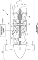
- An example HEP 100 is shown in FIG. 1 and generally comprises a thermal engine 110, an electric motor 130 and a propeller 120.
- the thermal engine 110 is, in this example, a combustion engine, and more particularly a turboprop gas turbine engine.
- Other types of internal combustion engines such as gas turbine (e.g., turboshaft, turbofan) engines, piston engines and rotary engines, may also be suitable.
- the thermal engine 110 may be any system that converts heat or thermal energy to mechanical energy which can then be used to drive a load, such as the propeller 120.
- the load may be any suitable air mover for propelling a fixed-wing aircraft or a rotary wing aircraft.
- the load may be a bladed rotor such as a propeller, a fan, a helicopter main rotor and/or a helicopter tail rotor.
- the electric motor 130 may be any suitable type of electric motor, including an electric machine that may be driven as a motor and as a generator.
- the propeller 120 may be attached to (i.e., in torque-transmitting engagement with) a shaft 108 and driven by one or more turbines of the turbine section 106 via the shaft 108.
- a compressor section 114 for pressurizing ambient air
- a combustor 116 in which the compressed air is mixed with fuel and ignited for generating an annular stream of hot combustion gases
- a turbine section 106 for extracting energy from the combustion gases driving the rotation of the propeller 120 through the shaft 108.
- the propeller 120 converts rotary motion from the shaft 108 of the thermal engine 110 to provide propulsive force (e.g., thrust) for the aircraft.
- the propeller 120 may be a variable-pitch propeller capable of generating forward and reverse thrust and may comprise two or more propeller blades 122.
- the thermal engine 110 may drive the propeller 120 via a (e.g., speed-reducing) gear box (RGB) 132.
- RGB speed-reducing gear box
- the electric motor 130 may also be configured to drive the propeller 120 via RGB 132 and the shaft 108.
- the electric motor 130 may convert electricity to motive power that is in turn converted to thrust by the propeller 120.
- the HEP 100 thus includes two motive power sources, namely the electric motor 130 and the thermal engine 110, whose power may be combined (e.g., through the RGB 132) and used to drive the load (e.g., propeller 120). While the thermal engine 110 and the electric motor 130 are shown in this example to be coupled to the propeller 120 through the RGB 132, other configurations are also contemplated. For example, in other configurations, a power plant having a thermal engine and an electric motor may be coupled to one or more loads without a gear box.
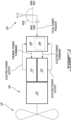
- a power management system 200 is coupled to the HEP 100, which includes the thermal engine 110, electric motor 130, and a combining gearbox 232 (which can also provide the mechanical speed reduction typically provided by the reduction gearbox 132).
- a total power request is received, for example from a power lever 202 (also known as "throttle lever") in an aircraft cockpit, at the power management system 200.
- the position of power lever 202 may provide a power lever angle (PLA) representative of the total power request.
- PPA power lever angle
- the total power request may come from another aircraft or avionic system, or from an engine system or controller.
- the total power request may be sent from the power lever 202 to another system which may then provide the information to the power management system 200.
- the power management system 200 may convert the total power request into an electric power request and a thermal power request in accordance with a desired proportion of electric power and thermal power.
- the electric power request and the thermal power request may then be converted into an electric power command and a thermal power command, respectively, which are used to drive the electric motor 130 and thermal engine 110, respectively.
- the breakdown between thermal power and electric power may vary anywhere between 0% to 100% for either power source. It will be appreciated that in embodiments which do not include a thermal engine 110, the total power request may be used as the electric power request without any conversion to proportions of thermal power and electric power.
- two separate power lanes are provided from the power management system 200 to the HEP 100, one for the thermal power command and one for the electric power command, and are referred to herein as the thermal power lane and the electric power lane, respectively.
- the actual power output by the HEP 100 for each power source may be provided to the power management system 200 (e.g., by a torque and/or speed sensor, such as speed/torque sensor 402 as shown in FIG. 5A as power is the product of torque and angular velocity).
- the power management system 200 may be configured to detect faults that have the potential to affect the power command or power output to a given power lane by comparing a given power command to an actual output power.
- a fault in the electric power lane may be detected when the electric power output deviates from the electric power command by more than a first threshold.
- a fault in the thermal power lane may be detected when the thermal power output deviates by the thermal power command by more than a second threshold.
- the first and second thresholds may be the same or different, taking into account the differences between the thermal engine 110 and the electric motor 130.
- the fault may be confirmed using a timer, i.e. the deviation is maintained for a predetermined time (e.g., the fault meets a persistence criteria).
- the power management system 200 is implemented within a single controller 204.
- the controller 204 may be part of a multi channel or single channel arrangement, each channel having one or more processors, each processor having one or more cores.
- Various functions of the system 200 may be split across channels and/or processors and/or cores. For example, a first channel may convert the thermal power request to a thermal power command while a second channel may convert the electric power request to an electric power command.
- a first processor or first core may convert the thermal power request to a thermal power command while a second processor or core may convert the electric power request to an electric power command.
- Fault detection and fault accommodation may be provided in a same or separate channel, processor, and/or core.
- FIG. 3 is a schematic diagram of an exemplary embodiment of the power management system 200.
- the power management system 200 may include a first controller and a second controller, with each controller dedicated to one of the thermal engine 110 and the electric motor 130.
- a thermal engine controller 302 may receive the thermal power request and determine the thermal power command based on the thermal power request.
- other parameters such as aircraft parameters, thermal engine parameters, and ambient operating conditions may be used to determine the thermal power command.
- aircraft parameters may include but are not limited to flight phase, aircraft weight, fuel status, battery state of charge, weight on wheels, flap setting, and secondary system requests (e.g. bleed system, hydraulic drive system, electrical power generation system).
- Examples of engine parameters may include but are not limited to temperature, rotational speed, pressure, fuel rate, output torque, and internal system operating conditions.
- Examples of ambient operating conditions may include but are not limited to outside air temperature, altitude, Mach number, calibrated air speed, and ambient pressure.
- a motor controller 304 may receive the electric power request and may determine the electric power command based on the electric power request. In some embodiments, other parameters such as the aircraft parameters, electric motor parameters, and the ambient operating conditions may be used to determine the thermal power command.
- Examples of the electric motor parameters may include but are not limited to voltage, current, torque, speed, power factor, efficiency, internal temperature, and internal resistance.
- a third controller may be provided in the power management system 200 for converting the total power request into the thermal power request and the electric power request.
- a power controller 306 may be found upstream of the thermal engine controller 302 and the motor controller 304 to perform this function.
- the power controller 306 may form part of the thermal engine controller 302 or the motor controller 304 instead of being provided separately therefrom.
- each controller 302, 304 may be configured to perform fault detection for its own power lane in a form of self-diagnosis.
- the motor controller 304 may receive the electric power output from the HEP 100 and compare the electric power output to its own electric power command to detect a fault.
- the motor controller 304 may send a fault flag which may be converted to a (e.g., visual and/or aural) notification to the pilot of the aircraft (e.g.
- warning signal in the cockpit of the aircraft.
- This warning signal may be perceived by the pilot, who may then mitigate the fault or failure by moving the power lever 202 to the idle (off) position (as shown in FIG. 2 ) in order to reduce the speed and torque of electric motor 130 to zero.
- motor controller 304 When the power lever 202 is in the idle position, motor controller 304 will receive a signal from the PLA position sensor 203 (shown in FIG. 5B ) and generate an electric power command to set the electric motor 130 torque to zero.
- a potential problem underlying power management system 200 is that in the event of the fault associated with the electric motor 130 being a failure in the motor controller 304, PLA position sensor 203 or other part of the electric power lane, the zero torque command generated via the PLA sensor 203 may not be effective due to the fault. If the motor controller 304 or associated control electronics are malfunctioning, the total power request from power lever 202 might not get converted to the corresponding electric power command correctly. In addition, if motor controller 304 is malfunctioning, the electric power command might not be transferred to electric motor 130. Thus, it is possible that the zero torque command set by the pilot via power lever 202 in response to a detected overspeed or overtorque condition might not be delivered to the electric motor 130, which could result in the overspeed or overtorque condition persisting.
- the systems and methods described herein may allow for electric motor 130 to be deactivated (e.g., stopped, shut down) without relying on a single communication path.
- the systems and methods described herein may rely on a separate communication path (e.g., independent of motor controller 304 and/or of PLA position sensor 203) for deactivating electric motor 130.
- FIG. 4 is a flow diagram of method 1000 of operating an aircraft power plant such as HEP 100 including electric motor 130.
- Method 1000 may be carried out using fault mitigation system 400 described below or using other system.
- Method 1000 may include elements of fault mitigation system 400, 450 and/or other actions disclosed herein.
- method 1000 may include:
- controlling electric motor 130 according to the power request may be carried out via a first communication path between power lever 202 and electric motor 130.
- the electric motor 130 may be deactivated via a second communication path between power lever 202 and electric motor 130.
- the second communication path being separate from the first communication path.
- the second communication path may exclude the first communication path.
- the second communication path may exclude one or more elements of the first communication path.
- the second communication path may exclude controller 304 or 304a.
- the second communication path may be independent of the first communication path so that a failure along the first communication path may still permit electric motor 130 to be deactivated via the second communication path.
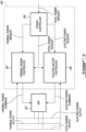
- FIG. 5A is a schematic diagram of an exemplary fault mitigation system 400, in accordance with some embodiments.
- the position (e.g., PLA) of power lever 202 will be detected by a sensor (e.g., PLA sensor 203), which may convert the PLA to a signal in the form of a power request received at motor controller 304.
- Motor controller 304 may then convert the PLA to a corresponding power command used to control electric motor 130.
- the output power of electric motor 130 may be measured by one or more speed and/or torque sensors 402.
- system 400 includes two sensors, namely speed/torque sensor A 402a and speed/torque sensor B 402b.
- Electric motor 130 power output signals may be transmitted from speed/torque sensor 402a to motor controller 304.
- electric power output signal may be transmitted to a display 404 in the cockpit of the aircraft (e.g., to provide a visual indication of the current electric power output to pilot 406).
- Motor controller 304 may be configured to compare the electric power output to the electric power command that motor controller 304 is using to drive electric motor 130.
- Speed/torque sensor A 402a may provide feedback to motor controller 304 to permit closed loop control of electric motor 130.
- motor controller 304 may determine that a fault (e.g., overspeed or overtorque condition) is associated with electric motor 130, and may cause a warning to be delivered to pilot 406 via cockpit display 404.
- a fault e.g., overspeed or overtorque condition
- speed/torque sensor B 402b may provide torque and/or speed feedback to pilot 406 via cockpit display 404 (e.g., directly) without electric motor controller 304 as an intermediary. Pilot 406 may then determine whether the fault (e.g., overspeed or overtorque condition) exists based on the feedback provided via cockpit display 404.
- the pilot 406 may adjust the position of power lever 202 to an idle (off) position.
- power lever 202 includes a switch 410 or switch 510 which is (e.g., directly) operatively connected to an electrical power input electric motor 130 via a communication path that excludes motor controller 304. Switch 410, 510 may be used to generate the deactivation request.
- switch 410, 510 is positioned on power lever 202 or otherwise associated with power lever 202 so as to be easily accessible and/or actuatable by pilot 406. In some embodiments, activation of switch 410, 510 will disconnect electrical power from electric motor 130, thereby resulting in de-powering electric motor 130. In other words, switch 410, 510 may be operated as a "kill" switch for electric motor 130.
- switch 410, 510 may be a micro-switch. That is, switch 410, 510 may require relatively little amount of force to be actuated. Thus, pilot 406 may quickly and easily actuate switch 410, 510 in the event of a detected fault to quickly deactivate (e.g., de-power) electric motor 130, and activate a direct shutdown path for electric motor 130 without motor controller 304 as a possible point of failure in the de-powering mechanism. In some embodiments, switch 410, 510 may act as a relay between an electric power input to electric motor 130 and a power source for powering electric motor 130.
- switch 410, 510 may provide a method of de-powering electric motor 130 which is independent from the operation of motor controller 304.
- pilot 406 may have an alternative communication path for disabling electric motor 130.
- actuating switch 410, 510 may result in the electric motor 130 being powered down in a shorter amount of time than via motor controller 304, as the use of switch 410, 510 may avoid the signal processing time required to convert the PLA into a command for electric motor 130 by motor controller 304.
- the positioning of switch 410, 510 on or in the vicinity of the power lever 202 may allow for a deactivation request to be transmitted directly to electric motor 130, and the position of power lever 202 may still be utilized by power controller 306 and thermal engine controller 302 to control thermal engine 110.
- power controller 306 may be configured to adjust the thermal power command based on, for example, whether switch 410, 510 has been actuated or power lever 202 is in the designated throttle position for deactivating electric motor 130. For example, power controller 306 may increase the thermal power command to compensate for a loss of electric power when electric motor 130 is shut down.
- power controller 306 may be configured to shut down thermal engine 110 when switch 410, 510 has been actuated (e.g., by cutting the fuel supply to thermal engine 110).
- FIG. 5B is another schematic diagram of an exemplary fault mitigation system 450, in accordance with some embodiments.
- System 450 includes components similar to system 400, and incorporates a dual-channel electric motor controller architecture (depicted as motor controller 304a and motor controller 304b in FIG. 5B ). As depicted, certain aspects of system 450 function in a similar manner to those of system 400. For example, speed/torque sensor A 402a and speed/torque sensor B 402b may detect the electric output power from electric motor 130 and transmit a power output signal to cockpit display 404 in the cockpit of the aircraft and transmit feedback on the operation of electric motor 130 to motor controller 304a.
- speed/torque sensor A 402a and speed/torque sensor B 402b may detect the electric output power from electric motor 130 and transmit a power output signal to cockpit display 404 in the cockpit of the aircraft and transmit feedback on the operation of electric motor 130 to motor controller 304a.
- motor controller 304a may determine that electric motor 130 is in a fault (e.g., overspeed or overtorque) condition, and cause a warning to be delivered to pilot 406 via cockpit display 404 in the cockpit of the aircraft.
- speed/torque sensor B 402b may provide torque and/or speed feedback to pilot 406 via cockpit display 404 (e.g., directly) without electric motor controller 304a as an intermediary. Pilot 406 may then determine whether the fault (e.g., overspeed or overtorque condition) exists based on the feedback provided via cockpit display 404.
- the pilot 406 in response to receiving the overspeed/overtorque warning signal on cockpit display 404 in the cockpit of the aircraft, the pilot 406 may adjust the position of power lever 202 to an idle (off) position.
- a switch 410, 510 may be associated power lever 202 may be operatively connected to motor controller 304b.
- motor controller 304b may be a separate controller from motor controller 304b and may serve as a separate channel functioning independently of motor controller 304a.
- movement of power lever 202 to the idle position may trigger the actuation of switch 410, 510, or switch 410, 510 may be separately manually actuated by pilot 406 so that the actuation of switch 410, 510 is not caused by movement of power lever 202.
- Actuation of switch 410, 510 may transmit a deactivation request to motor controller 304b, which may then, in response to receiving the deactivation request, de-power electric motor 130.
- the signal from switch 410, 510 may be routed via a fully independent communication path to de-power and shut down electric motor 130.
- system 450 may also not have a single point of failure for shutting down electric motor 130. For example, in the event that motor controller 304a were to fail, and motor controller 304b may still function to shut down electric motor 130.
- systems 400, 450 may allow electric motor overspeed/overtorque conditions to be quickly detected and mitigated while respecting industry standards and guidelines for airborne electronic hardware.
- ARP Aerospace Recommended Practice
- ARP4754A Guidelines For Development Of Civil Aircraft and Systems
- RTCA Radio Technical Commission for Aeronautics
- RTCA DO-254 Design Assurance Guidance for Airborne Electronic Hardware
- FAA Federal Aviation Administration
- DAL A through E Development Assurance Levels
- DAL A is the most stringent, defined as a "catastrophic" effect, while a DAL E will not affect the safety of the aircraft.
- Meeting DAL A compliance for complex electronic hardware requires a much higher level of verification and validation than a DAL E compliance.
- Most avionic platforms are DAL B or DAL C and may not be suitable for mitigating a fault such as an overspeed or overtorque condition in electric motor 130. It may be desirable or required to have such fault mitigation meet DAL A.
- Systems 400, 450 for mitigating electric motor faults are provided with architectures that have two independent, segregated ways of deactivating electric motor 130, so as to meet industry regulations such as RTCA DO-254.
- Critical electric motor 130 control functions may be performed by components having a critical, or highest, level of reliability and non-critical electric motor control functions may be performed by components having a non-critical level of reliability.
- a component is deemed to have a critical level of reliability if a comprehensive combination of deterministic tests and analyses can ensure correct functional performance under all foreseeable operating conditions with no anomalous behavior.
- a component that cannot have a correct functional performance ensured by tests and analyses alone cannot be assigned a critical level of reliability and is therefore deemed to have a non-critical level of reliability. There may be multiple levels of non-criticality.
- the critical electric motor 130 functions may comprise cutting electrical power to electric motor 130, and may be performed with components having a critical level of reliability, which is equivalent to DAL A for RTCA DO-254. Deactivating electric motor 130 may be performed via switch 410, 510.
- components such as switch 410, 510 having a critical level of reliability may be non-complex electronic hardware components. This may include deterministic (or binary) logic components, such as Boolean gates, non-complex hardware switches and commercial off-the-shelf (COTS) components.
- COTS commercial off-the-shelf
- Firmware which is understood as a specific class of software that provides low-level control for a device's specific hardware, may also fall into the category of non-complex electric hardware components.
- Various architectures are contemplated for the failure mitigation system 400, 450, including having a direct communication path between switch 410, 510 and electric motor 130, and as part of a dual-channel configuration including motor controllers 304a, 304b having independent and redundant paths for deactivating (e.g., shutting down) electric motor 130.
- FIG. 6A is a schematic diagram of an exemplary switch 410 that may be incorporated in fault mitigation system 400 or in fault mitigation system 450.
- Switch 410 may be disposed on a handle of power lever 202 or on another part of power lever 202 and may be manually actuatable by pilot 406 independently of the positional setting of power lever 202.
- Switch 410 may be disposed at a convenient location that is readily accessible by pilot 406.
- switch 410 may be actuatable via a (e.g., spring loaded) push button disposed on power lever 202.
- depressing the push button may electrically connect terminals 420, 422 together, which may be part of a relay switch configuration where the application of (e.g., low) direct-current (DC) voltage LV may cause the opening of contactor 424, which may be normally closed during normal operation of electric motor 130.
- the opening of contactor 424 may cause (e.g., high-voltage) battery 426 to become disconnected from inverter 428 and hence from electric motor 130.
- the actuation of switch 410 may be considered a deactivation request for deactivating electric motor 130.
- the deactivation request may be used to open contactor 424 or to instruct motor controller 304b to deactivate electric motor 130.
- the communication path between switch 410 and contactor 424 (or between switch 410 and motor controller 304b) may exclude controller 304 or 304a.
- FIG. 6B is a schematic diagram of an exemplary switch 510 that may be incorporated in fault mitigation system 400 or fault mitigation system 450.
- Switch 510 may be actuatable from the movement (e.g., rotation) of power lever 202 to a prescribed PLA (e.g., idle or other position) of power lever 202.
- a prescribed PLA e.g., idle or other position
- the movement of power lever 202 to the idle position may electrically connect terminals 420, 422 together, which may be part of a relay switch configuration as shown in FIG. 6A to cause opening of contactor 424.
- the movement of power lever 202 away from the idle position may electrically disconnect terminals 420, 422.
- the deactivation request from switch 510 may be used to open contactor 424 or to instruct motor controller 304b to deactivate electric motor 130 by causing electric motor 130 to output zero torque (i.e., motor controller 304b executing a zero torque command).
- the communication path between switch 510 and contactor 424 or between switch 510 and motor controller 304b may exclude controller 304a.
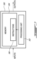
- the power management system 200 and/or fault mitigation system 400 may be implemented with one or more computing devices 500, an example of which is illustrated in FIG. 7 .
- computing devices 500 may be the same or different types of devices.
- the thermal engine controller 302 and/or power controller 306 may be implemented as part of a full-authority digital engine controls (FADEC) or other similar device, including electronic engine control (EEC), engine control unit (ECU), electronic propeller control, propeller control unit, and the like.
- the motor controller 304 may be implemented as part of a motor controller (MC), electric motor controller (EMC), electric powertrain controller (EPC), and the like. Other embodiments may also apply.
- the computing device 500 may comprise a processing unit 502 and a memory 504 which has stored therein computer-executable instructions 506.
- the processing unit 502 may comprise any suitable devices configured to implement the method 1000 such that instructions 506, when executed by the computing device 500 or other programmable apparatus, may cause the functions/acts/steps performed as part of the method 1000 as described herein to be executed.
- the processing unit 502 may comprise, for example, any type of general-purpose microprocessor or microcontroller, a digital signal processing (DSP) processor, a central processing unit (CPU), an integrated circuit, a field programmable gate array (FPGA), a reconfigurable processor, other suitably programmed or programmable logic circuits, or any combination thereof.
- DSP digital signal processing
- CPU central processing unit
- FPGA field programmable gate array
- reconfigurable processor other suitably programmed or programmable logic circuits, or any combination thereof.
- the memory 504 may comprise any suitable known or other machine-readable storage medium.
- the memory 504 may comprise non-transitory computer readable storage medium, for example, but not limited to, an electronic, magnetic, optical, electromagnetic, infrared, or semiconductor system, apparatus, or device, or any suitable combination of the foregoing.
- the memory 504 may include a suitable combination of any type of computer memory that is located either internally or externally to device, for example random-access memory (RAM), read-only memory (ROM), compact disc read-only memory (CDROM), electro-optical memory, magnetooptical memory, erasable programmable read-only memory (EPROM), and electrically-erasable programmable read-only memory (EEPROM), Ferroelectric RAM (FRAM) or the like.
- Memory 504 may comprise any storage means (e.g., devices) suitable for retrievably storing machine-readable instructions 506 executable by processing unit 502.
- the methods and systems for fault mitigation of an aircraft power plant described herein may be implemented in a high level procedural or object oriented programming or scripting language, or a combination thereof, to communicate with or assist in the operation of a computer system, for example the computing device 500.
- the methods and systems for fault mitigation may be implemented in assembly or machine language.
- the language may be a compiled or interpreted language.
- Program code for implementing the methods and systems for fault mitigation may be stored on a storage media or a device, for example a ROM, a magnetic disk, an optical disc, a flash drive, or any other suitable storage media or device.
- the program code may be readable by a general or special-purpose programmable computer for configuring and operating the computer when the storage media or device is read by the computer to perform the procedures described herein.
- Embodiments of the methods and systems for fault mitigation may also be considered to be implemented by way of a non-transitory computer-readable storage medium having a computer program stored thereon.
- the computer program may comprise computer-readable instructions which cause a computer, or more specifically the processing unit 502 of the computing device 500, to operate in a specific and predefined manner to perform the functions described herein, for example those described in the method 1000.
Landscapes
- Engineering & Computer Science (AREA)
- Aviation & Aerospace Engineering (AREA)
- Control Of Electric Motors In General (AREA)
Applications Claiming Priority (1)
| Application Number | Priority Date | Filing Date | Title |
|---|---|---|---|
| US18/213,483 US12617539B2 (en) | 2023-06-23 | Method and system for mitigating an electric motor fault in an aircraft power plant |
Publications (1)
| Publication Number | Publication Date |
|---|---|
| EP4480826A1 true EP4480826A1 (fr) | 2024-12-25 |
Family
ID=91620656
Family Applications (1)
| Application Number | Title | Priority Date | Filing Date |
|---|---|---|---|
| EP24183554.5A Pending EP4480826A1 (fr) | 2023-06-23 | 2024-06-20 | Procédé et système pour atténuer un défaut de moteur électrique dans une centrale électrique d'aéronef |
Country Status (1)
| Country | Link |
|---|---|
| EP (1) | EP4480826A1 (fr) |
Cited By (1)
| Publication number | Priority date | Publication date | Assignee | Title |
|---|---|---|---|---|
| EP4671131A1 (fr) * | 2024-06-28 | 2025-12-31 | Pratt & Whitney Canada Corp. | Systèmes et procédés de commande d'un moteur électrique d'un système de propulsion d'aéronef |
Citations (2)
| Publication number | Priority date | Publication date | Assignee | Title |
|---|---|---|---|---|
| US20210347490A1 (en) * | 2020-05-07 | 2021-11-11 | Gulfstream Aerospace Corporation | Hybrid jet electric aircraft |
| US20230002034A1 (en) * | 2021-07-01 | 2023-01-05 | Beta Air, Llc | System for fixed-pitch lift configured for use in an electric aircraft |
-
2024
- 2024-06-20 EP EP24183554.5A patent/EP4480826A1/fr active Pending
Patent Citations (2)
| Publication number | Priority date | Publication date | Assignee | Title |
|---|---|---|---|---|
| US20210347490A1 (en) * | 2020-05-07 | 2021-11-11 | Gulfstream Aerospace Corporation | Hybrid jet electric aircraft |
| US20230002034A1 (en) * | 2021-07-01 | 2023-01-05 | Beta Air, Llc | System for fixed-pitch lift configured for use in an electric aircraft |
Cited By (1)
| Publication number | Priority date | Publication date | Assignee | Title |
|---|---|---|---|---|
| EP4671131A1 (fr) * | 2024-06-28 | 2025-12-31 | Pratt & Whitney Canada Corp. | Systèmes et procédés de commande d'un moteur électrique d'un système de propulsion d'aéronef |
Also Published As
| Publication number | Publication date |
|---|---|
| US20240425187A1 (en) | 2024-12-26 |
Similar Documents
| Publication | Publication Date | Title |
|---|---|---|
| EP4032812B1 (fr) | Procédés et systèmes de gestion d'alimentation d'un moteur électrique hybride | |
| US11794916B2 (en) | Control systems for hybrid electric power plants | |
| CN110844088B (zh) | 用于飞行器的容错性混合电动推进系统 | |
| US20200339268A1 (en) | Control systems for hybrid electric powerplants | |
| EP3101277B1 (fr) | Aéronef avec ventilateur de refroidissement de frein | |
| KR102951857B1 (ko) | 공중 정지가 가능한 항공기 및 관련 항공기를 제어하기 위한 방법 | |
| US12300991B2 (en) | Overspeed and/or overtorque protection for hybrid electric aircraft propulsion system | |
| EP4035998B1 (fr) | Système et procédé de détection de défaillance d'un dispositif de rétroaction d'hélice | |
| CA2923405C (fr) | Mecanisme et methode de protection contre le charriage | |
| US11821325B2 (en) | System and method for detecting failure of a propeller control unit | |
| EP3909856A1 (fr) | Systèmes de commande pour des centrales électriques hybrides | |
| EP4019396B1 (fr) | Système et procédé de détection de dysfonctionnement d'hélice | |
| EP4480826A1 (fr) | Procédé et système pour atténuer un défaut de moteur électrique dans une centrale électrique d'aéronef | |
| CA3079061A1 (fr) | Systeme et procede de detection d`un evenement puissant non sollicite ou incontrolable dans un aeronef | |
| CN111792021B (zh) | 用于使螺旋桨顺桨的方法和系统 | |
| US12617539B2 (en) | Method and system for mitigating an electric motor fault in an aircraft power plant | |
| US20220298971A1 (en) | Method for protecting an aircraft engine on spin-up |
Legal Events
| Date | Code | Title | Description |
|---|---|---|---|
| PUAI | Public reference made under article 153(3) epc to a published international application that has entered the european phase |
Free format text: ORIGINAL CODE: 0009012 |
|
| STAA | Information on the status of an ep patent application or granted ep patent |
Free format text: STATUS: THE APPLICATION HAS BEEN PUBLISHED |
|
| AK | Designated contracting states |
Kind code of ref document: A1 Designated state(s): AL AT BE BG CH CY CZ DE DK EE ES FI FR GB GR HR HU IE IS IT LI LT LU LV MC ME MK MT NL NO PL PT RO RS SE SI SK SM TR |
|
| STAA | Information on the status of an ep patent application or granted ep patent |
Free format text: STATUS: REQUEST FOR EXAMINATION WAS MADE |
|
| 17P | Request for examination filed |
Effective date: 20250625 |
|
| GRAP | Despatch of communication of intention to grant a patent |
Free format text: ORIGINAL CODE: EPIDOSNIGR1 |
|
| STAA | Information on the status of an ep patent application or granted ep patent |
Free format text: STATUS: GRANT OF PATENT IS INTENDED |
|
| INTG | Intention to grant announced |
Effective date: 20260126 |