EP4480882A1 - Système d'entraînement - Google Patents
Système d'entraînement Download PDFInfo
- Publication number
- EP4480882A1 EP4480882A1 EP24183770.7A EP24183770A EP4480882A1 EP 4480882 A1 EP4480882 A1 EP 4480882A1 EP 24183770 A EP24183770 A EP 24183770A EP 4480882 A1 EP4480882 A1 EP 4480882A1
- Authority
- EP
- European Patent Office
- Prior art keywords
- joint
- elements
- engagement elements
- engagement
- operating position
- Prior art date
- Legal status (The legal status is an assumption and is not a legal conclusion. Google has not performed a legal analysis and makes no representation as to the accuracy of the status listed.)
- Pending
Links
Images

Classifications
-
- B—PERFORMING OPERATIONS; TRANSPORTING
- B66—HOISTING; LIFTING; HAULING
- B66B—ELEVATORS; ESCALATORS OR MOVING WALKWAYS
- B66B13/00—Doors, gates, or other apparatus controlling access to, or exit from, cages or lift well landings
- B66B13/02—Door or gate operation
- B66B13/12—Arrangements for effecting simultaneous opening or closing of cage and landing doors
-
- B—PERFORMING OPERATIONS; TRANSPORTING
- B66—HOISTING; LIFTING; HAULING
- B66B—ELEVATORS; ESCALATORS OR MOVING WALKWAYS
- B66B13/00—Doors, gates, or other apparatus controlling access to, or exit from, cages or lift well landings
- B66B13/02—Door or gate operation
- B66B13/14—Control systems or devices
- B66B13/16—Door or gate locking devices controlled or primarily controlled by condition of cage, e.g. movement or position
- B66B13/18—Door or gate locking devices controlled or primarily controlled by condition of cage, e.g. movement or position without manually-operable devices for completing locking or unlocking of doors
- B66B13/20—Lock mechanisms actuated mechanically by abutments or projections on the cages
Definitions
- the present invention relates to a driver system for the joint opening and closing of an elevator car door and an elevator shaft door, which is assigned to the elevator car, comprising a base unit, a pair of a first and a second engagement element, which extend substantially parallel and vertically and which are displaceable between an open operating position in which they have a first horizontal distance from one another, and a closed operating position in which they have a second horizontal distance from one another, wherein the first horizontal distance is greater than the second horizontal distance and the closed operating position corresponds to a state in which the two engagement elements mechanically engage with counter elements of the elevator shaft door, and at least a first and a second joint arrangement which carry the pair of engagement elements in a parallelogram configuration and are rotatable for displacing the engagement elements between the open operating position and the closed operating position.
- Such carrier systems are used according to the prior art to be transferred between the closed position, in which the engagement elements, also referred to as “swords", are brought closer together, and the open position.
- the present invention relates in particular to a carrier system of the so-called “clamp type", in which the closed position corresponds to that in which the engagement elements engage with corresponding counter-elements of the elevator shaft door in order to enable a joint movement of the two doors for opening and closing, while in the open position the elevator car door can be moved vertically together with the elevator car in the elevator shaft.
- the two blades are brought closer together in a plane parallel to the planes of the two doors in order to finally interact with the counter-elements mentioned which are provided on the lift shaft door in order to allow the lift car door and the lift shaft door to be opened and closed together.
- the elevator car is assigned a drive device which is coupled to the driver system and interacts in such a way that when the two doors are opened, in a first step the engagement elements are first transferred from their open position to their closed position and then a joint displacement of the doors coupled in this way is effected, while when the doors are closed a reverse movement sequence occurs.
- the open position corresponds to the state in which the elevator car can be moved vertically in the elevator shaft
- the closed position corresponds to the state in which the elevator car door and the elevator shaft door can be opened and closed together, so that the elevator car must be vertically immobile in a predetermined orientation opposite the elevator shaft door.
- the driver systems used to date for this purpose are relatively complex in design, since in addition to the two engagement elements, a locking mechanism must also be provided for safety reasons, which blocks the elevator car door against manual opening when the drive device is de-energized to drive the joint opening and closing of the elevator car door and the elevator shaft door and to transfer the engagement elements between their open and closed positions or in other conceivable malfunction cases.
- the carrier systems used to date generally required a total of three rails and three rollers or counter-elements interacting with them or similarly complex safety devices, which requires a large number of components and complex control of the respective operation of these components.
- driver systems of the type described above which are characterized by a simplified design with consistently safe operation and consequently offer savings potential with regard to their production as well as their maintenance and operation.
- the first joint arrangement comprises a first joint element carrying the first engagement element and a second joint element carrying the second engagement element, wherein the first joint element is pivotally connected to the base unit and can be driven to perform a pivoting movement for a transition between the closed operating position and the open operating position, wherein the first joint element and the second joint element are furthermore pivotally connected relative to one another via a first bearing, wherein the second joint arrangement furthermore comprises a third joint element carrying the first engagement element and a fourth joint element carrying the second engagement element, wherein the third joint element is pivotally connected to the base unit and the third joint element and the fourth joint element are pivotally connected relative to one another via a second bearing, wherein the driver system furthermore comprises a Preload arrangement which cooperates with one of the joint arrangements and/or one of the engagement elements in such a way that the engagement elements are preloaded towards one another, wherein the joint arrangements are designed in such a way that the preload
- the trigger element in a state in which, for example in the event of a failure of the drive device between two floors, the engagement elements move beyond the closed operating position into the locking position due to the lack of engagement with the counter elements, the trigger element is in a position in which it cannot pivot the locking element into its open position, so that it remains in the closed position and manual opening of the Elevator cabin door is prevented in such a state.
- the term "otherwise force-free state" is to be understood in such a way that neither a drive motor for transferring the engagement elements between their closed and open operating positions nor counter elements associated with an elevator shaft door act on the engagement elements.
- a clamp-type driver system is created with a reduced number of necessary components and a simplified mechanism, which can nevertheless ensure the same level of operational safety as similar systems currently on the market with a much more complex safety system.
- the preload arrangement can in particular comprise two elastic elements, in particular springs, wherein one of the elastic elements acts on one of the joint elements and the other of the elastic elements acts between this joint element and the other joint element of the corresponding joint arrangement.
- the locking element can be provided with a guide curve along which the trigger element can run for transferring the joint element into its open position, although alternatively other shapes of the locking element could also be conceivable which enable actuation in the closed operating position of the engagement elements, but prevent it in the locking position of the engagement elements.
- an elastic element in particular a spring, can be provided which preloads the locking element into its closed position, so that the action of the trigger element on the locking element must first overcome the corresponding preload force of the elastic element in order to be able to transfer the locking element into its open position and consequently to allow the elevator car door to open.
- the locking element could also be activated solely by the action of be preloaded into the closed position by gravity, provided that a suitable geometry and weight distribution on the locking element can ensure its safe functioning.
- the locking position can be defined in such a way that the first and second joint elements and/or the third and fourth joint elements come into contact with one another, so that at this point a further approach of the two engagement elements to one another is prevented and the locking position is clearly defined.
- additional or alternative means could also be provided to determine the minimum distance between the two engagement elements corresponding to the locking position, for example stop elements permanently installed on the base unit.
- a toothed belt coupling can be provided to drive the pivoting movement for the transition between the closed operating position and the open operating position of the engagement elements, which forms a particularly simple, low-maintenance and reliable embodiment of such a drive or a corresponding coupling to a motor.
- the trigger element rolls on a counter surface of the locking element in order to transfer the latter into its open position in a predetermined operating sequence
- the trigger element is designed as an eccentric bolt, preferably with a ball bearing, in order to keep the wear of the corresponding parts as low as possible and to enable a low-noise actuation of the locking element.
- At least one of the engagement elements can be provided with a hole pattern to allow variable positioning with respect to the joint units, for example to enable fine adjustment of the driver system to local conditions and geometries. or to enable a single type of carrier system to be used with different designs of elevator cars and/or elevator shaft doors.
- the present invention relates to an elevator car door, comprising an inventive driver system of the type just described and a drive device which is designed to trigger a pivoting of the joint elements, wherein said drive device can act in particular on the toothed belt coupling already mentioned above.
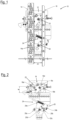
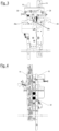
- FIG. 1 to 6 an embodiment of a driver system according to the invention for the joint opening and closing of a lift car door and lift shaft door (not shown) which is assigned to the lift car is shown in different views or different operating states, wherein the driver system is generally designated by the reference numeral 10.
- the driver system 10 comprises a base unit 12, in particular in the form of several mounting plates, to which the components described below are mounted or hinged directly or indirectly in the manner described. Furthermore, for example, in Fig. 1 a pair of a first or left engagement element 14 and a second or right engagement element 16 are shown, which in Fig. 1 initially in an open operating position with a first horizontal distance A1.
- the left engagement element 14 is provided with a hole pattern 14a, which enables variable mounting thereof in different relative orientations with respect to the joint arrangements 18 and 20 described below.
- the hole pattern 14a the embodiment shown in the present figures is merely an example; in alternative variants, for example, the right engagement element 16 or both engagement elements 14 and 16 could also be provided in a similar manner with hole patterns for variable mounting thereof in order to be able to adapt the driver system 10 to compensate for tolerances on the one hand and to enable use of a single type of driver system with different elevator car doors and elevator shaft doors on the other.
- the driver system 10 comprises a first or upper joint arrangement 18 and a second or lower joint arrangement 20, which the pair of engagement elements 14, 16 in a parallelogram configuration and are each pivotally mounted on the base unit 12 in order to be able to adjust the distance between the two engagement elements 14 and 16.
- the first joint arrangement 18 comprises a first joint element 18a, which carries the first engagement element 14, and a second joint element 18b, which carries the second engagement element 16.
- the first joint element 18a and the second joint element 18b are connected to one another via a first bearing 18c, which allows the two joint elements 18a and 18b to perform a pivoting relative movement to one another.
- the first joint element 18a is coupled to a toothed belt coupling 22 for driving a pivoting movement thereof, which enables the transition between the open operating position of the engagement elements 14, 16 from Fig. 1 and the closed operating position discussed below from Fig. 4
- the connection of the first joint element 18a to the base unit 12 is again made via a pivot bearing 18d, so that a pivoting transition of the engagement elements 14, 16 carried by the joint unit 18 between the positions shown in the present figures is possible.
- the second joint arrangement 20 also comprises two joint elements, namely a third joint element 20a and a fourth joint element 20b, which are pivotally coupled to one another via a second bearing 20c.
- the third joint element 20a and the fourth joint element 20b are further preloaded in the direction of movement of the two engagement elements 14, 16 towards one another via a preload arrangement 24 in the form of a first spring 24a acting on the third joint element and supported on the base unit 12 and a second spring 24b acting between the third joint element 20a and the fourth joint element 20b.
- the pivoting of the third joint element 20a is made possible by a mounted coupling to the base unit 12 by means of a further pivot bearing 20d, which is aligned in the vertical direction with the above-mentioned pivot bearing 18d of the first joint unit 18.
- the Figures 1 and 2 shown open operating position of the engagement elements 14 and 16 is a state in which a travel operation of the corresponding elevator car in an associated elevator shaft is possible, since the engagement elements 14 and 16 are aligned in such a way that they do not engage with external elements.
- a force is required that counteracts the loading by the preload arrangement 24, which is carried out by means of a motor (not shown) via the toothed belt coupling 22, whereby the joint arrangements 18 and 20 and thus the engagement elements 14 and 16 are pivoted into a so-called "zero-degree position".
- This case corresponds to the one in Fig. 1 indicated and already mentioned above maximum distance A1 of the engagement elements 14 and 16.
- Fig. 3 which shows a rear view of the driver system 10 in the operating state from the Figures 1 and 2
- the driver system 10 further comprises a locking element 26, which in the Fig. 3 shown configuration prevents the elevator car door from opening by a suitable engagement with a counter element (not shown here), wherein it is preloaded into this closed position by an elastic element 28, in this case a spring.
- the locking element 26 also has a guide curve 26a, which is shaped in such a way that when a suitable force is applied to the guide curve 26a, pivoting of the locking element 26 relative to the base unit 12 about its pivot axis 26b is triggered, which corresponds to a transition of the locking element 26 from the closed position mentioned to an open position in which opening of the elevator car door is permitted and possible.
- a trigger element 30 is also assigned to the first joint arrangement 18 in a suitable manner, in the embodiment shown here an eccentric bolt with a ball bearing, which, however, in the operating state from the Figures 1 to 3 is initially spaced from the locking element 26 and in particular the guide curve 26a, so that the locking element in this state, which in the manner mentioned corresponds to the driving state of the elevator car, remains in its closed position and thus prevents the elevator car door from opening in the desired manner.
- the Fig. 4 in a similar view as the Fig. 1 the driver system 10 in a closed operating position of the engagement elements 14 and 16, in which they are brought closer to each other by pivoting the joint arrangements 18 and 20 up to a distance A2 which is smaller than the distance A1 described above. At this distance A2, the two engagement elements 14 and 16 come into engagement with counter elements 32 which are assigned to the elevator shaft door.
- the deflection angle of the joint units 18 and 20 compared to their position in Fig. 1 can, for example, be in the range of about 50°.
- the counter elements 32 act in such a way that, on the one hand, the clamping thereof by means of the engagement elements 14 and 16 enables a joint opening of the elevator car door and the elevator shaft door and, on the other hand, a further approach of the two engagement elements 14 and 16 beyond the second horizontal distance A2 is prevented.
- This state therefore corresponds to a deactivation of the motor which acts on the toothed belt coupling 22, the transition from the open to the closed position being caused by the action of the preload arrangement 24 and being limited by the counter elements 32 with regard to the approach of the two engagement elements 14 and 16 to the second horizontal distance A2.
- the trigger element 30 on the first joint arrangement 18 is located precisely in the area of the guide curve 26a of the locking element 26 due to the pivoting movement carried out and by this mechanical engagement such a lever force is exerted on the locking element 26 that it pivots against the action of the spring 28 about the pivot axis 26b into its open position, in which allows and enables the opening of the elevator car door.
- the operating position corresponds to the Figures 4 and 5 each a state in which the elevator car door is aligned in the desired manner with an elevator shaft door and consequently the engagement elements 14 and 16 come into contact with the counter elements 32 and interact in such a way that the locking element 26 is simultaneously transferred into its open position and thus a joint opening of the elevator car door and the elevator shaft door is made possible.
- Fig. 6 which shows a state in which the drive motor acting on the toothed belt coupling 22 is de-energized, but the elevator car is outside the unlocking zone, ie not in the desired alignment with an elevator shaft door. In such a case, it must be ensured that the locking element 26 prevents the elevator car door from opening and accordingly remains in its closed position.
- the two engagement elements 14 and 16 pivot towards each other up to a distance A3, which is referred to here as the locking position and, for example, prevents the joint units 18, 20 from pivoting relative to the position from Fig. 1 by approximately 57°.
- This locking position is ultimately determined by the fact that the first and second joint elements 18a, 18b and/or the third and fourth joint elements 20a, 20b rest against each other in pairs and thus further pivoting is prevented.
- Fig. 6 compared to Fig. 5 It can be seen that due to the third horizontal distance A3 being smaller than the second horizontal distance A2, the trigger element 30 is not in the area of the guide curve 26a of the locking element 26, but is located further in the direction of the spring 28, where a corresponding guide curve is not present and therefore no Force effect of the trigger element 30 on the locking element 26 is possible. Accordingly, in the Fig. 6 shown locking position, the locking element 26 remains in its closed position, into which it is preloaded by the spring 28, and consequently, in the state described here, opening of the elevator car door is prevented, which represents a safety measure in states in which the drive motor has lost power or fails for other reasons, but the elevator car is not in a designated position relative to an elevator shaft door.
Landscapes
- Engineering & Computer Science (AREA)
- Mechanical Engineering (AREA)
- Automation & Control Theory (AREA)
- Elevator Door Apparatuses (AREA)
Applications Claiming Priority (1)
| Application Number | Priority Date | Filing Date | Title |
|---|---|---|---|
| DE102023116443.0A DE102023116443A1 (de) | 2023-06-22 | 2023-06-22 | Mitnehmersystem |
Publications (1)
| Publication Number | Publication Date |
|---|---|
| EP4480882A1 true EP4480882A1 (fr) | 2024-12-25 |
Family
ID=91663956
Family Applications (1)
| Application Number | Title | Priority Date | Filing Date |
|---|---|---|---|
| EP24183770.7A Pending EP4480882A1 (fr) | 2023-06-22 | 2024-06-21 | Système d'entraînement |
Country Status (2)
| Country | Link |
|---|---|
| EP (1) | EP4480882A1 (fr) |
| DE (1) | DE102023116443A1 (fr) |
Citations (3)
| Publication number | Priority date | Publication date | Assignee | Title |
|---|---|---|---|---|
| CN111470397A (zh) * | 2020-05-28 | 2020-07-31 | 上海贝思特门机有限公司 | 一种内夹式集成轿门锁同步门刀 |
| DE102019204321A1 (de) * | 2019-03-28 | 2020-10-01 | Franz Xaver Meiller Fahrzeug- Und Maschinenfabrik - Gmbh & Co Kg | Variables Mitnehmersystem |
| DE102020204593A1 (de) * | 2020-04-09 | 2021-10-14 | Franz Xaver Meiller Fahrzeug- Und Maschinenfabrik - Gmbh & Co Kg | Kabinentüranordnung für einen aufzug mit einer mechanischen kabinentürverriegelung |
Family Cites Families (4)
| Publication number | Priority date | Publication date | Assignee | Title |
|---|---|---|---|---|
| FI100517B (fi) * | 1995-09-13 | 1997-12-31 | Kone Oy | Menetelmä hissin tasonoven sulkemisessa ja mukaanottaja |
| FI101784B1 (fi) * | 1995-09-13 | 1998-08-31 | Kone Corp | Menetelmä hissin tasonoven liikuttamiseksi ja mukaanottaja |
| FI102673B1 (fi) * | 1996-02-28 | 1999-01-29 | Kone Corp | Mukaanottaja ja lukituslaite |
| CN205527239U (zh) * | 2016-02-04 | 2016-08-31 | 杭州优迈科技有限公司 | 一种集成轿门锁同步门刀及同步门刀系统 |
-
2023
- 2023-06-22 DE DE102023116443.0A patent/DE102023116443A1/de not_active Withdrawn
-
2024
- 2024-06-21 EP EP24183770.7A patent/EP4480882A1/fr active Pending
Patent Citations (3)
| Publication number | Priority date | Publication date | Assignee | Title |
|---|---|---|---|---|
| DE102019204321A1 (de) * | 2019-03-28 | 2020-10-01 | Franz Xaver Meiller Fahrzeug- Und Maschinenfabrik - Gmbh & Co Kg | Variables Mitnehmersystem |
| DE102020204593A1 (de) * | 2020-04-09 | 2021-10-14 | Franz Xaver Meiller Fahrzeug- Und Maschinenfabrik - Gmbh & Co Kg | Kabinentüranordnung für einen aufzug mit einer mechanischen kabinentürverriegelung |
| CN111470397A (zh) * | 2020-05-28 | 2020-07-31 | 上海贝思特门机有限公司 | 一种内夹式集成轿门锁同步门刀 |
Also Published As
| Publication number | Publication date |
|---|---|
| DE102023116443A1 (de) | 2024-12-24 |
Similar Documents
| Publication | Publication Date | Title |
|---|---|---|
| EP1541517B1 (fr) | Dispositif sur une cabine d'ascenseur pour coupler temporairement un panneau de porte de cabine avec un panneau de porte palière et pour activer un mécanisme de verrouillage | |
| EP2297018B1 (fr) | Système de porte d'ascenseur à dispositif de verrouillage de porte de cabine | |
| AT505923B1 (de) | Verriegelungsvorrichtung einer tür | |
| EP1713712B9 (fr) | Dispositif d'actionnement et de verrouillage de portes d'ascenseurs | |
| EP1717392B1 (fr) | Arrangement de serrure supplémentaire pour porte coulissante de véhicule automobile | |
| WO2018033601A1 (fr) | Ensemble charnière | |
| EP0513509A1 (fr) | Ascenseur | |
| EP1594717A1 (fr) | Siege de vehicule reglable en hauteur comportant une unite de blocage pour collisions | |
| EP3317142B1 (fr) | Siège de véhicule réglable en hauteur équipé d'une unité anticollision | |
| EP2430273B1 (fr) | Entraînement de volet de meuble, pouvant pivoter | |
| EP1914189A1 (fr) | Mécanisme de verrouillage pour la porte d'une cabine d'ascenseur | |
| AT511710B1 (de) | Vorrichtung zum anstellen einer motorhaube | |
| DE10040593C2 (de) | Verriegelungseinrichtung für längsverstellbare Sitze, insbesondere Kraftfahrzeugsitze | |
| AT414115B (de) | Bodenverriegelung | |
| DE102023117383A1 (de) | Antriebsanordnung für eine Klappe eines Kraftfahrzeugs mit einer Karosserie | |
| EP4098556B1 (fr) | Unité de porte pour un véhicule | |
| DE102023116443A1 (de) | Mitnehmersystem | |
| WO2025003108A1 (fr) | Ensemble d'entraînement pour un volet d'un véhicule automobile présentant un carrosserie | |
| EP3901082B1 (fr) | Agencement de porte de cabine pour un ascenseur doté d'un verrouillage mécanique de porte de cabine | |
| EP4185508B1 (fr) | Système de porte pour un véhicule et véhicule comprenant un système de porte | |
| DE102014216951B3 (de) | Verriegelungsvorrichtung | |
| EP4201864A1 (fr) | Système d'entraînement | |
| DE10346148B4 (de) | Vorrichtung zur Verriegelung und zur Entriegelung, insbesondere eines Beschlags zur Verstellung von Teilen eines Fahrzeugsitzes, und Verfahren | |
| EP2071110B1 (fr) | Dispositif de guidage et de verrouillage d'un système basculant coulissant | |
| EP4559738A1 (fr) | Mécanisme de déverrouillage et siège de véhicule |
Legal Events
| Date | Code | Title | Description |
|---|---|---|---|
| PUAI | Public reference made under article 153(3) epc to a published international application that has entered the european phase |
Free format text: ORIGINAL CODE: 0009012 |
|
| STAA | Information on the status of an ep patent application or granted ep patent |
Free format text: STATUS: THE APPLICATION HAS BEEN PUBLISHED |
|
| AK | Designated contracting states |
Kind code of ref document: A1 Designated state(s): AL AT BE BG CH CY CZ DE DK EE ES FI FR GB GR HR HU IE IS IT LI LT LU LV MC ME MK MT NL NO PL PT RO RS SE SI SK SM TR |
|
| STAA | Information on the status of an ep patent application or granted ep patent |
Free format text: STATUS: REQUEST FOR EXAMINATION WAS MADE |
|
| 17P | Request for examination filed |
Effective date: 20250623 |