EP4480887A1 - Dispositif de levage à fixer au plafond ou au mur - Google Patents
Dispositif de levage à fixer au plafond ou au mur Download PDFInfo
- Publication number
- EP4480887A1 EP4480887A1 EP24183161.9A EP24183161A EP4480887A1 EP 4480887 A1 EP4480887 A1 EP 4480887A1 EP 24183161 A EP24183161 A EP 24183161A EP 4480887 A1 EP4480887 A1 EP 4480887A1
- Authority
- EP
- European Patent Office
- Prior art keywords
- roller
- sheet
- support structure
- attached
- rotation
- Prior art date
- Legal status (The legal status is an assumption and is not a legal conclusion. Google has not performed a legal analysis and makes no representation as to the accuracy of the status listed.)
- Withdrawn
Links
Images
Classifications
-
- B—PERFORMING OPERATIONS; TRANSPORTING
- B66—HOISTING; LIFTING; HAULING
- B66C—CRANES; LOAD-ENGAGING ELEMENTS OR DEVICES FOR CRANES, CAPSTANS, WINCHES, OR TACKLES
- B66C13/00—Other constructional features or details
- B66C13/04—Auxiliary devices for controlling movements of suspended loads, or preventing cable slack
- B66C13/06—Auxiliary devices for controlling movements of suspended loads, or preventing cable slack for minimising or preventing longitudinal or transverse swinging of loads
-
- A—HUMAN NECESSITIES
- A61—MEDICAL OR VETERINARY SCIENCE; HYGIENE
- A61G—TRANSPORT, PERSONAL CONVEYANCES, OR ACCOMMODATION SPECIALLY ADAPTED FOR PATIENTS OR DISABLED PERSONS; OPERATING TABLES OR CHAIRS; CHAIRS FOR DENTISTRY; FUNERAL DEVICES
- A61G7/00—Beds specially adapted for nursing; Devices for lifting patients or disabled persons
- A61G7/10—Devices for lifting patients or disabled persons, e.g. special adaptations of hoists thereto
- A61G7/1013—Lifting of patients by
- A61G7/1015—Cables, chains or cords
-
- B—PERFORMING OPERATIONS; TRANSPORTING
- B66—HOISTING; LIFTING; HAULING
- B66D—CAPSTANS; WINCHES; TACKLES, e.g. PULLEY BLOCKS; HOISTS
- B66D3/00—Portable or mobile lifting or hauling appliances
- B66D3/18—Power-operated hoists
Definitions
- Lifting devices are known which require a supporting structure resting on the floor.
- such lifting devices suffer from the drawback of taking up space on the floor and therefore needing sufficient free space on the floor for their installation.
- lifting devices such as winches or hoists that can be mounted on the ceiling or wall.
- Such lifting devices operate with ropes or chains, thus with essentially one-dimensional traction members. This can lead to problems in the stability of the load during vertical movement.
- a lifting device thus configured, in particular due to the fact that the traction member is formed by a sheet, i.e. a two-dimensional member, and due to the fact that the coupling means extend substantially over the entire width of the sheet, it is possible to vertically move loads of various kinds, in a stable and safe manner, using a single device or at most two devices operating in combination.
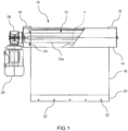
- a lifting device according to an embodiment of the present invention is generally indicated 10.
- the lifting device 10 further comprises a support structure 14 on which the roller 12 is supported in a rotatable manner for rotation about an axis of rotation coinciding with the longitudinal axis x.
- the support structure 14 is advantageously formed by a box-like casing, for example of a parallelepiped shape, within which the roller 12 is accommodated. In this way, the support structure 14 has the function not only of support, but also of protection, for the roller 12.
- the support structure 14 is provided with attachment means for attachment of the support structure itself to a ceiling or wall of a building so that the axis of rotation of the roller 12 is oriented horizontally.
- the lifting device 10 further comprises, as a traction member, a sheet 18 which is made, for example, of polyamide or another suitable material to ensure adequate tensile strength.
- a sheet 18 which is made, for example, of polyamide or another suitable material to ensure adequate tensile strength.
- the term 'sheet' is to be understood to mean in general a two-dimensional traction member, i.e. a traction member having one of the three dimensions (in this case the thickness) negligible in relation to the other two, unlike a one-dimensional traction member, such as for example a rope, cable or band.
- the sheet 18 has a width greater than the diameter of roller 12.
- the sheet 18 is fixed at a first end thereof to the lateral surface 12a of the roller 12 so that it can be wound on, or unwound from, the roller as a result of the rotation of the latter about its axis of rotation.
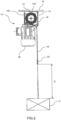
- the sheet 18 is provided with coupling means which extend substantially over the whole width of the sheet 18 and are configured to enable a load C to be vertically moved (shown in Figure 2 ) to be coupled to the sheet.
- such coupling means are formed by an elongated end plate 20 with a length substantially equal to the width of the sheet 18, said plate having a plurality of holes 22, for example arranged equally spaced from each other in the direction of the length of the end plate 20 (i.e. in the direction of the width of the sheet 18).
- the holes 22 serve to allow insertion of hooks or other suitable coupling members with which to couple the load C to be vertically moved to the end plate 20, and thus to the sheet 18.
- the roller 12 is advantageously provided with a pair of lateral guide discs 24 (one of which can be seen in Figure 1 ) positioned at the opposite axial ends of the roller.
- the lifting device 10 further comprises actuating means operatively associated with the roller 12 to control its rotation in one direction or the other about its axis of rotation to cause the winding of the sheet 18 on the roller 12, and thus the upward movement of the end plate 20 (and of the load C coupled thereto), or respectively the unwinding of the sheet 18 from the roller 12, and thus the downward movement of the end plate 20 (and of the load C coupled thereto).
- actuating means include, for example, a motor 26, in particular an electric motor, which may be directly or indirectly connected to the roller 12 and may be mounted inside or outside the latter.
- the motor 26 is mounted outside the roller 12, in particular with the axis of rotation of its rotor oriented vertically, and an angle gear reducer 28 is interposed between the motor 26 and the roller 12.
- the motor may be arranged with the axis of its rotor oriented horizontally, in particular coinciding with the longitudinal axis x of the roller 12.
- a gear reducer may be provided between the motor and the roller.
- the aforesaid actuating means also include a special control member, such as a push-button (which may be either physical or virtual), to enable the operator to control the rotation of the motor 26, and thus of the roller 12, in one direction or the other and thus cause the lifting or lowering of the sheet 18, and therefore of the load C.
- a special control member such as a push-button (which may be either physical or virtual) to enable the operator to control the rotation of the motor 26, and thus of the roller 12, in one direction or the other and thus cause the lifting or lowering of the sheet 18, and therefore of the load C.
- the lifting device 10 is designed to vertically move loads C of various kinds, in particular loads with masses between 50kg and 1000kg. As shown in Figure 2 , the load C to be moved may be coupled directly to the end plate 20, using the holes 22 provided therein. However, it is possible to interpose one or more traction members between the load C and the end plate 20. Still with reference to Figure 2 , the maximum stroke of the vertical movement of the load C that can be controlled with the lifting device 10 is indicated by D. Said maximum stroke will of course depend on the length of the sheet 18.
- the load C is moved vertically using only one lifting device 10.
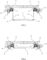
- two lifting devices 10 are provided for supporting the load C to be vertically moved, which loading platform is coupled with two opposite sides thereof parallel to the end plates 20 attached to the sheets 18 of the two lifting devices 10.
- the two lifting devices 10 have their motors 26 arranged horizontally, i.e. arranged so that the axes of rotation of the respective rotors are oriented horizontally. More specifically, in the present case the sheets 18 of the two lifting devices 10 face each other, while the motors 26 are arranged on opposite sides of each other.
- Figure 3 shows the condition in which the loading platform P is lowered
- Figure 4 shows the condition in which the loading platform P is at the maximum possible height (condition corresponding to the complete winding of the sheets 18 on the respective rollers 12).
- an appropriate synchronous control of the two motors 26 will be provided in this case to ensure that the loading platform P maintains a horizontal attitude during upward or downward movement.
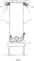
- a stretcher B or other suitable support means for receiving a person, to the end plates 20 of the sheets 18 of the two lifting devices 10.
- a stretcher or other suitable support means for receiving a person
- the lifting device of the present invention allows loads of various kinds to be moved vertically in a stable and safe manner using a single device or, at most, two devices operating in combination, without requiring a supporting structure resting on the floor and thus without taking up space on the floor.
Landscapes
- Health & Medical Sciences (AREA)
- Engineering & Computer Science (AREA)
- Mechanical Engineering (AREA)
- Nursing (AREA)
- Life Sciences & Earth Sciences (AREA)
- Animal Behavior & Ethology (AREA)
- General Health & Medical Sciences (AREA)
- Public Health (AREA)
- Veterinary Medicine (AREA)
- Invalid Beds And Related Equipment (AREA)
Applications Claiming Priority (1)
| Application Number | Priority Date | Filing Date | Title |
|---|---|---|---|
| IT102023000012657A IT202300012657A1 (it) | 2023-06-20 | 2023-06-20 | Dispositivo di sollevamento fissabile a soffitto o a parete |
Publications (1)
| Publication Number | Publication Date |
|---|---|
| EP4480887A1 true EP4480887A1 (fr) | 2024-12-25 |
Family
ID=87974678
Family Applications (1)
| Application Number | Title | Priority Date | Filing Date |
|---|---|---|---|
| EP24183161.9A Withdrawn EP4480887A1 (fr) | 2023-06-20 | 2024-06-19 | Dispositif de levage à fixer au plafond ou au mur |
Country Status (2)
| Country | Link |
|---|---|
| EP (1) | EP4480887A1 (fr) |
| IT (1) | IT202300012657A1 (fr) |
Citations (3)
| Publication number | Priority date | Publication date | Assignee | Title |
|---|---|---|---|---|
| US5667035A (en) * | 1995-10-19 | 1997-09-16 | Hughes; Douglas J. | Overhead platform elevation device |
| US20090255889A1 (en) * | 2007-11-14 | 2009-10-15 | Kurt Geffe | Storage system |
| ES2328238T3 (es) * | 2002-12-05 | 2009-11-11 | EISENMANN ANLAGENBAU GMBH & CO. KG | Dispositivo elevador movil. |
-
2023
- 2023-06-20 IT IT102023000012657A patent/IT202300012657A1/it unknown
-
2024
- 2024-06-19 EP EP24183161.9A patent/EP4480887A1/fr not_active Withdrawn
Patent Citations (3)
| Publication number | Priority date | Publication date | Assignee | Title |
|---|---|---|---|---|
| US5667035A (en) * | 1995-10-19 | 1997-09-16 | Hughes; Douglas J. | Overhead platform elevation device |
| ES2328238T3 (es) * | 2002-12-05 | 2009-11-11 | EISENMANN ANLAGENBAU GMBH & CO. KG | Dispositivo elevador movil. |
| US20090255889A1 (en) * | 2007-11-14 | 2009-10-15 | Kurt Geffe | Storage system |
Also Published As
| Publication number | Publication date |
|---|---|
| IT202300012657A1 (it) | 2024-12-20 |
Similar Documents
| Publication | Publication Date | Title |
|---|---|---|
| JP2764891B2 (ja) | 揚重装置及び、該装置を用いた構築資材の運搬方法 | |
| EP3699133B1 (fr) | Ensemble de levage, ascenseur de saut et procédé de saut | |
| CN110844743B (zh) | 跃层电梯和跃层方法 | |
| US6860367B1 (en) | Elevator system having drive motor located below the elevator car | |
| RU2704655C1 (ru) | Фасадный подъемник с вертикальным и горизонтальным перемещением люльки | |
| JPH0829904B2 (ja) | エレベータの据付工法 | |
| EP4480887A1 (fr) | Dispositif de levage à fixer au plafond ou au mur | |
| JPH1077171A (ja) | エレベータ用巻上装置 | |
| JP2000313578A (ja) | 工事用エレベータ | |
| KR20230163597A (ko) | 감아올림 가능한 차 갑판 패널 | |
| JP2665686B2 (ja) | 垂直型交通機関 | |
| KR101432451B1 (ko) | 엘리베이터 장치 | |
| KR20230161600A (ko) | 승강기구 | |
| JPH05246654A (ja) | エレベータ制御ケーブルの架設装置 | |
| JPH10316331A (ja) | クライミングエレベータ | |
| CN219990959U (zh) | 一种吊装设备 | |
| EP1967478A1 (fr) | Appareil électromécanique pour l'élévation de personnes et/ou des charges | |
| JP2998068B2 (ja) | 昇降装置 | |
| KR200236339Y1 (ko) | 회전형 리프트 크레인 | |
| EP0298924A1 (fr) | Appareil pour augmenter la capacité de stockage d'une pièce et en particulier d'un garage pour voiture | |
| JP2000118912A (ja) | エレベーター装置 | |
| JP2002096991A (ja) | 荷役用昇降装置 | |
| JP2001287881A (ja) | 工事用エレベータおよびその据付方法 | |
| JP2005231780A (ja) | エレベータ装置およびそのエレベータ装置の据付工法 | |
| KR0139129B1 (ko) | 건축공사용 기자재의 양중장치및 양중방법 |
Legal Events
| Date | Code | Title | Description |
|---|---|---|---|
| PUAI | Public reference made under article 153(3) epc to a published international application that has entered the european phase |
Free format text: ORIGINAL CODE: 0009012 |
|
| STAA | Information on the status of an ep patent application or granted ep patent |
Free format text: STATUS: THE APPLICATION HAS BEEN PUBLISHED |
|
| AK | Designated contracting states |
Kind code of ref document: A1 Designated state(s): AL AT BE BG CH CY CZ DE DK EE ES FI FR GB GR HR HU IE IS IT LI LT LU LV MC ME MK MT NL NO PL PT RO RS SE SI SK SM TR |
|
| STAA | Information on the status of an ep patent application or granted ep patent |
Free format text: STATUS: THE APPLICATION IS DEEMED TO BE WITHDRAWN |
|
| 18D | Application deemed to be withdrawn |
Effective date: 20250626 |