EP4480930A1 - Réacteur à biofilm de microalgues - Google Patents
Réacteur à biofilm de microalgues Download PDFInfo
- Publication number
- EP4480930A1 EP4480930A1 EP24181977.0A EP24181977A EP4480930A1 EP 4480930 A1 EP4480930 A1 EP 4480930A1 EP 24181977 A EP24181977 A EP 24181977A EP 4480930 A1 EP4480930 A1 EP 4480930A1
- Authority
- EP
- European Patent Office
- Prior art keywords
- housing
- cultivation
- water
- wastewater
- biofilm
- Prior art date
- Legal status (The legal status is an assumption and is not a legal conclusion. Google has not performed a legal analysis and makes no representation as to the accuracy of the status listed.)
- Pending
Links
Images


Classifications
-
- C—CHEMISTRY; METALLURGY
- C02—TREATMENT OF WATER, WASTE WATER, SEWAGE, OR SLUDGE
- C02F—TREATMENT OF WATER, WASTE WATER, SEWAGE, OR SLUDGE
- C02F3/00—Biological treatment of water, waste water, or sewage
- C02F3/32—Biological treatment of water, waste water, or sewage characterised by the animals or plants used, e.g. algae
- C02F3/322—Biological treatment of water, waste water, or sewage characterised by the animals or plants used, e.g. algae use of algae
-
- C—CHEMISTRY; METALLURGY
- C02—TREATMENT OF WATER, WASTE WATER, SEWAGE, OR SLUDGE
- C02F—TREATMENT OF WATER, WASTE WATER, SEWAGE, OR SLUDGE
- C02F2201/00—Apparatus for treatment of water, waste water or sewage
- C02F2201/009—Apparatus with independent power supply, e.g. solar cells, windpower or fuel cells
-
- C—CHEMISTRY; METALLURGY
- C02—TREATMENT OF WATER, WASTE WATER, SEWAGE, OR SLUDGE
- C02F—TREATMENT OF WATER, WASTE WATER, SEWAGE, OR SLUDGE
- C02F2203/00—Apparatus and plants for the biological treatment of water, waste water or sewage
- C02F2203/006—Apparatus and plants for the biological treatment of water, waste water or sewage details of construction, e.g. specially adapted seals, modules, connections
-
- C—CHEMISTRY; METALLURGY
- C02—TREATMENT OF WATER, WASTE WATER, SEWAGE, OR SLUDGE
- C02F—TREATMENT OF WATER, WASTE WATER, SEWAGE, OR SLUDGE
- C02F2203/00—Apparatus and plants for the biological treatment of water, waste water or sewage
- C02F2203/008—Mobile apparatus and plants, e.g. mounted on a vehicle
-
- C—CHEMISTRY; METALLURGY
- C02—TREATMENT OF WATER, WASTE WATER, SEWAGE, OR SLUDGE
- C02F—TREATMENT OF WATER, WASTE WATER, SEWAGE, OR SLUDGE
- C02F2301/00—General aspects of water treatment
- C02F2301/02—Fluid flow conditions
- C02F2301/022—Laminar
-
- C—CHEMISTRY; METALLURGY
- C02—TREATMENT OF WATER, WASTE WATER, SEWAGE, OR SLUDGE
- C02F—TREATMENT OF WATER, WASTE WATER, SEWAGE, OR SLUDGE
- C02F2303/00—Specific treatment goals
- C02F2303/14—Maintenance of water treatment installations
-
- C—CHEMISTRY; METALLURGY
- C02—TREATMENT OF WATER, WASTE WATER, SEWAGE, OR SLUDGE
- C02F—TREATMENT OF WATER, WASTE WATER, SEWAGE, OR SLUDGE
- C02F3/00—Biological treatment of water, waste water, or sewage
- C02F3/02—Aerobic processes
- C02F3/10—Packings; Fillings; Grids
- C02F3/103—Textile-type packing
-
- C—CHEMISTRY; METALLURGY
- C12—BIOCHEMISTRY; BEER; SPIRITS; WINE; VINEGAR; MICROBIOLOGY; ENZYMOLOGY; MUTATION OR GENETIC ENGINEERING
- C12M—APPARATUS FOR ENZYMOLOGY OR MICROBIOLOGY; APPARATUS FOR CULTURING MICROORGANISMS FOR PRODUCING BIOMASS, FOR GROWING CELLS OR FOR OBTAINING FERMENTATION OR METABOLIC PRODUCTS, i.e. BIOREACTORS OR FERMENTERS
- C12M21/00—Bioreactors or fermenters specially adapted for specific uses
- C12M21/02—Photobioreactors
Definitions
- the present invention relates to devices for the treatment of wastewater, in particular for the phytoremediation of wastewater (agricultural, industrial, municipal, aquaculture) by means of a harvestable stationary algal biofilm.
- ATS Algal Turf Scrubber
- WO 96/13970 A1 and US 4,333,263 are open to the environment and can lead to the release of potentially harmful wastewater and biofilm.
- Commercially available algae biofilm systems as described in WO 2014/172691 A1 use a mobile cultivation area that is moved via pulleys.
- This and similar systems such as in WO 2014/085869 A1 have disadvantageous, high energy consumption, technical failure rates and expenses, as well as biofilm detachment.
- Enclosed systems such as in DE 20 2019 005 811 U1 are only suitable for very small amounts of wastewater and are unsuitable for use on a large scale.
- WO 2024/038269 A1 in which either suspensions/solutions of microorganisms or microorganisms floating on an aqueous stream are used
- DE 10 2014 000 691 A1 concerning circulating suspensions of free-floating microorganisms
- US 2007/0155006 A1 concerning the cultivation of microalgae in suspensions
- WO 2015/087169 A2 concerning a variety of culture reactors for microorganisms in dedicated racks
- DE 10 2009 016 738 A1 concerning special reactor systems for culture suspensions.
- the object of the present invention was therefore to provide, with regard to the state of the art, new devices for the treatment of waste water, which are improved compared to the devices of the state of the art and have new or further advantages.
- the reference system used in the present invention is an observer standing upright on the ground in front of the object under discussion.
- ambient temperature means a temperature of 20°C. Temperatures are in degrees Celsius (°C), unless otherwise stated.
- the reactions or process steps mentioned are carried out at atmospheric pressure, i.e. at about 1013 kPa.
- harvesting means that the biomass or the (algal) biofilm is removed from the cultivation area, for example scraped off; the product thus obtained can then be used as biofertilizer, biogas substrate, soil conditioner, soil additive or similar.
- the present invention relates in a first subject to a device for the treatment of waste water which comprises all the necessary devices or equipment in a (single) completely closed housing.
- the interior of the housing is preferably made of corrosion-resistant and washable material or is coated with such a material; an example of a preferred material is stainless steel.
- a certain level of humidity is present in the interior. This can condense on the walls and - with other materials - could lead to corrosion.
- the present invention is based on biological processes. In this respect, it is useful to be able to remove impurities from the surfaces (of the housing) (this could also lead to contamination of the purified water).
- the housing is a cuboid-shaped housing, preferably a container, possibly converted, particularly preferably a standard container or ISO container, possibly converted, in particular a 10-foot shipping container, 20-foot shipping container or 40-foot shipping container, possibly converted.
- a container possibly converted, particularly preferably a standard container or ISO container, possibly converted, in particular a 10-foot shipping container, 20-foot shipping container or 40-foot shipping container, possibly converted.
- such a container enables transport and mobile use, preferably by means of transport eyes and/or attachment of transverses and feet.
- the housing which is closed on all sides, has one or more opening and closing access points.
- these can be all types of access points, for example manholes, hatches, doors, etc.
- These are preferably doors that are either incorporated into the respective head sides of the housing or form the entire respective head sides; the latter is often the case with ISO containers, which are a preferred type of housing in the context of the present invention.
- two or more cultivation surfaces are arranged one above the other inside the housing. These are preferably arranged parallel to one another, i.e. in particular the planes formed by their base surfaces are parallel to one another. Furthermore, the cultivation surfaces (or the planes formed by their base surfaces) each have an inclination in relation to the horizontal of between 0.5° and 7.5°, preferably between 1° and 5°, particularly preferably between 1.5° and 3.5° and in particular 2°, with the base surface of the housing (bottom of the container) being considered as the horizontal.
- the individual cultivation surfaces can in principle be inclined in any way with respect to the housing, for example also diagonally within the housing, but it is preferred if they are inclined in such a way that, in a sectional view of the housing, they are inclined from one side of the housing to the opposite side, whereby it is not necessary and is generally not designed in such a way that the ends of the cultivation surfaces abut the side walls.
- supply and discharge devices for the waste water are provided at the inlet and outlet ends of the cultivation surface.
- cultivation surface is understood to mean flat, level workpieces that have longitudinal edges so that they form a space that is open on one side (at the top) and has a usable volume, with space and volume being formed by the base area, the side lengths and the lowest height of the edges, and which are intended to accommodate biofilms and, if necessary, growth aids (technically and scientifically also referred to as “substrate”) for the biofilms or the organisms that form the biofilms in the resulting volume.
- the longitudinal edges are between 1 cm and 10 cm high, particularly preferably between 2 cm and 5 cm.
- the workpieces formed in this way - cultivation surfaces - usually have, preferably, rectangular bases; however, parallelogram-like, trapezoidal, triangular, n-sided or ellipsoidal bases are also conceivable.
- cultivation areas with dimensions of 11500 mm x 1500 mm can be used in a 40-foot container, the sides of which are preferably bent up by 90° and then have a height of 30 mm.
- the cultivation surfaces are made in particular of inert, i.e. particularly corrosion-resistant, washable, chemical-resistant and reflective materials.
- inert i.e. particularly corrosion-resistant, washable, chemical-resistant and reflective materials.
- An example of such a material is stainless steel.
- the cultivation areas are not limited in their dimensions as long as they, and any other devices/equipment present, find space inside the housing of the device according to the invention.
- a stack of ten cultivation areas measuring 11500 mm x 1500 mm x 30 mm can easily be arranged on one half of the container, while leaving enough space in the other half to allow access; for example, as a maintenance arm.
- the distance between the individual cultivation areas in this embodiment can be, for example, 250 mm (area to area, not taking edge heights into account).
- the surfaces of the cultivation areas are "covered” by adhering biofilms (covered like a lawn), preferably by microalgae biofilms, whereby the biofilms adhering to the different cultivation areas are all the same, partly the same or all different, whereby “the same” preferably means that the same microorganisms are used.
- comparability refers to biofilms with a similar structure and similar function despite differentiated microbial composition. Even with the same inocculum, ultimately different biofilms can form on the flowways (cultivation areas; this is where the water flows) (mathematical-dynamic system); see also D.
- microalgae e.g. spirulina, chlorella
- prokaryotic kingdom bacteria
- eukaryotic kingdoms metazoans (ciliates) and fungi
- EPS extracellular polymeric substances
- locally occurring organisms are used for the biofilms (for example, microalgae from the local environment), thereby increasing environmental compatibility, because this avoids, for example, contamination of the environment by organisms not native to the area (keywords: neophyte or neomycete avoidance).
- biofilms covering cultivation surfaces means that the biofilms, preferably microalgae biofilms, adhere to the cultivation surfaces directly or to any growth material for the biofilm that may be present, i.e. are stationary within the scope of the usual operating conditions of the devices/methods according to the invention and are not detached by water flowing along the cultivation surfaces and in particular do not form suspensions (whereby individual or small numbers of detached microalgae that are washed away in suspension in flowing water are not understood as a suspension).
- the device according to the invention comprises at least one feed device for applying waste water to be treated to one or more cultivation areas.
- one device distributes the waste water applied to it to all cultivation areas.
- several feed devices may be present, which then either supply individual cultivation areas with waste water or several.
- the waste water is evenly distributed to all cultivation areas by a feed device.
- the at least one feed device within the scope of the present invention is arranged such that the water to be treated is applied to the higher end of the respective - inclined cultivation areas; in this way it is ensured that the wastewater flows along the cultivation areas driven by gravity and thus passes through the biofilms.
- the supply device for applying waste water to be treated comprises a controllable (adjustable) pump for the waste water.
- the device according to the invention also comprises at least one discharge device for the treated water, wherein the at least one discharge device is arranged such that it discharges the treated water from the lower end of the respective cultivation areas. It thus forms the counterpart to the feed device.
- the at least one feed device and the at least one discharge device comprised by the device according to the invention are, in the simplest case, simple pipes with branches to the individual cultivation areas. It is preferred if the feed devices have branches adapted to even distribution to the individual cultivation areas, for example different diameters, or corresponding control devices such as valves. In further preferred embodiments of the present invention, the branches to the individual cultivation areas have widenings, for example up to the entire width of the respective cultivation area, in order to ensure that the water is evenly applied to the respective cultivation area. In some preferred variants, the discharge devices have corresponding widenings to collect the purified water. In other variants, the cultivation areas have one or more drainage holes at their ends, to which the discharge device(s) is (are) then connected. If the drainage holes are designed to allow water to be collected at the bottom of the housing by means of a gutter or similar, then the drainage holes and the gutter are to be regarded as a drainage device.
- the at least one feed device and the at least one discharge device are preferably, but not necessarily, arranged inside the housing, so that the transport of the device is easier than if it were arranged on the outside.
- the at least one feed device and the at least one discharge device are designed such that they are provided with standardized connections so that the wastewater to be treated or the purified water can be connected to the existing water network or the like on site using conventional connecting elements.
- These standardized connections can, for example, be correspondingly standardized connections for hoses or pipes.
- this is not always necessary for the proper operation of the devices according to the invention, since it is also possible to simply add water to be purified to the feed device using, for example, a gutter or a funnel and, in the simplest case, to simply let the purified water run off into the environment (which would usually be a waste and is therefore not usually done).
- Another component of the device according to the invention is at least one ventilation device for the housing, configured to supply air, in particular ambient air, and to remove used air.
- this is a passive ventilation device, in particular in the form of ventilation holes that are incorporated into the housing.
- one or more ventilation holes are designed on the floor, or near the floor, of the housing, and one or more in the ceiling, or near the ceiling, of the housing.
- active ventilation devices are used, such as fans and/or blowers. It can be advantageous if shields are attached to the upper edges of the openings of the ventilation devices facing the environment, which, for example, prevent rain from entering. In the case of active ventilation devices, it is preferred in variants if the air is sucked in via a filter or the like.
- active or passive ventilation devices it is preferred if they can be closed at least to the outside (i.e. towards the outside of the housing) (which is particularly advantageous for transport).
- Yet another component is at least one device for supplying light to the biofilms, which can be passive or active. These are preferably designed so that they are controllable, i.e. the amount and intensity of the light entering the housing and in particular the cultivation surfaces can be adjusted. This can be controlled manually or electronically for the device(s) selected.
- variant b) is less common (among other things because there are hardly any containers that have corresponding ceiling designs and because the uppermost cultivation area shades the ones below), but is still just as possible as variants a) and c).
- Variants a) and b) are passive devices for supplying light, as they depend on whether and, if so, how much light is present or generated outside the housing.
- Variant c) is an active device, as it can generate light independently of the environment (assuming a power supply).
- the devices in variants a) and b) can be controlled by simple measures such as blinds, in particular reflective ones; however, they can also include electrically adjustable polarization filters or similar.
- the devices in variant c) can be controlled in various ways.
- a lamp can be controlled simply using a dimmer. If there are several individual lamp elements, these can also be dimmed independently of one another, or switched on or off independently of one another.
- Both the active and passive light supply devices can be modified by using filters so that only certain wavelengths or wavelength ranges of light reach the biofilms.
- the lamps can be positioned in any way; for example, they can be mounted on stands, attached to the walls or hung up.
- the lamps in particular LEDs, are designed like a curtain so that the lamps can be moved.
- the lamps hang from the housing ceiling and are attached in such a way that they can be moved individually or in groups, in particular sideways.
- This is a particularly flexible solution for supplying light, by means of which the light can be intensified or weakened simply by moving it to the desired locations.
- this lamp curtain does not touch the housing base but hangs above it, this solution is also advantageous from the point of view of easier cleaning options and hygiene.
- the housing has at least one translucent, preferably daylight-permeable, side element in a housing wall, and lamps arranged within the housing, preferably LEDs, in particular as a lamp curtain.
- lamps that are well known to experts can be used to illuminate plants.
- An example of commercially available (vertical) LED lighting technology in plant cultivation are lamps such as those available from Blooms Grow Tech ® .
- the device according to the invention can optionally have at least one supply device for CO2-containing gas.
- This gas serves to provide additional nutrients for the algae in the biofilms and is not always required, but is only used in accordance with the exact conditions (because there are cases in which no additional CO2 is necessary).
- the device according to the invention can comprise electronic and optionally hydraulic operating devices, such as in particular control and regulation devices for temperature, water flow, in particular in the biofilms, lighting, CO2 supply, ventilation, gas supply and discharge.
- the control devices can comprise, for example, sensors, for example for pH, conductivity, etc., whereby these can be IoT sensors in order to be able to track and monitor the data continuously and online, which then enables immediate intervention (manual or automated) if this appears necessary based on the data.
- These operating devices are not necessary in the simplest embodiment, when the wastewater is fed into the feed device, for example via gutters, the water simply runs through the biofilms and simply flows away at the end and only a translucent housing wall serves as lighting.
- water inflow and outflow as well as the flow rate through the biofilms are regulated or at least adjusted and monitored, so that electronic and optionally hydraulic operating devices are then present.
- These can be arranged in one or more housings and can be arranged inside or outside the housing of the device according to the invention. In preferred variants of the present invention, these are arranged inside so as not to impair the transportability (and stackability, etc.) of the device according to the invention.
- the housing and/or the operating devices have interfaces for the optional integration of CO2 supply, power supply from external sources for example and preferably photovoltaics and/or wind power.
- the device according to the invention has a warning system for pump, air conditioning system and/or LED stop.
- a growth material for the biofilm is first applied to the upper surfaces of the cultivation surfaces. And only then is the respective biofilm, preferably microalgae biofilm.
- this growth material can be made either from robust and durable material, preferably glass fiber fabric, polypropylene, stainless steel, particularly preferably as a net or fabric, in particular with a mesh size >2, or compostable material, preferably from linen, hemp, cotton, sisal, particularly preferably designed as a net or fabric, in particular with a mesh size >2; in the case of short cultivation cycles with a focus on biofilm/fertilizer production, this can also be jute, in particular a net or fabric, in particular with a mesh size >2, made of jute.
- the present invention is not limited to a precise number of cultivation surfaces arranged one above the other.
- at least 3, at least 4, at least 5, at least 6, at least 7, at least 8, at least 9, at least 10 or more cultivation surfaces are arranged one above the other in the housing.
- two openable and closable accesses are provided, which are located on two opposite sides of the housing and are designed as personal accesses.
- the cultivation surfaces are arranged in one half of the housing and the other half of the housing is configured as a (walk-in) maintenance room or maintenance area, and lamps are arranged in the middle of the housing, which are configured to illuminate the cultivation surfaces and the biofilms located thereon.
- the supply device for applying waste water to be treated (4) and The discharge device for the treated water (8) shall be provided with standard connections.
- one or more photovoltaic elements are arranged on the top of the device, which are configured to supply the internal electronics of the device with power.
- the device according to the invention also comprises secondary batteries that can be charged by the photovoltaic elements when a surplus of power is generated and that are able to supply the device according to the invention with power when the photovoltaic elements cannot generate power (for example at night).
- the device according to the invention is provided with corresponding interfaces which make it possible to supply the electricity generated by the photovoltaic elements to external consumers or a local power grid when the electricity generated is not currently needed by the device according to the invention.
- the photovoltaic elements are therefore optional devices in case a more self-sufficient or sustainable operation is desired.
- the device according to the invention comprises at least one integrated transport lock, in particular a main switch to power the container and/or a main shut-off valve to supply the ATS system with waste water.
- the device has a fresh water inlet at the foot end of the housing, in particular inside, which can be used in particular for the hygienic final cleaning of the equipment and the personnel (hand washing).
- the housing of the device according to the invention can, in preferred embodiments of the present invention, accordingly be an ISO container, for example a shipping container, particularly preferably a 40-foot container, 20-foot container or 10-foot container, particularly preferred is a 40-foot container.
- ISO container for example a shipping container, particularly preferably a 40-foot container, 20-foot container or 10-foot container, particularly preferred is a 40-foot container.
- the inclinations of the individual cultivation surfaces can be adjusted if necessary.
- the inclinations of the individual cultivation surfaces can be changed independently of one another.
- the inclination change can be carried out either manually or with mechanical/electronic support; for the latter purpose, motors are installed in particular.
- the various cultivation surfaces are movably mounted at their lower end and provided with locking lugs at their upper end, which can engage in corresponding recesses in support rods (similar to what is usual in shelving systems).
- a very simple way of implementing the cultivation surfaces arranged one above the other, but one that is possible within the scope of the present invention, is to use shelving systems in which the individual cultivation surfaces are arranged on the respective shelves, or the shelves themselves form the cultivation surfaces, whereby the shelves must be designed accordingly for this to work (in particular metal shelves), and the shelves are not inserted straight, but higher on one side than the other.
- all existing cultivation surfaces are arranged parallel to one another and all inclined in the same direction and no cultivation surfaces are inclined in the other direction.
- wastewater can be treated within the scope of the present invention, provided that it is not toxic to the available biofilms.
- wastewater can also be treated that is toxic to some species but not to others - then other organisms (tolerant or resistant to this wastewater) would be suitable for the biofilm.
- wastewater examples include: municipal wastewater, wastewater from/from animal husbandry, or also biogas wastewater, industrial wastewater from food production and processing (non-critical), from healthcare facilities (critical if contaminated with pharmaceuticals or pathogens), from textile processing (critical if still contaminated with dyes or fixers), from contaminated production facilities (critical if contaminated with heavy metals or PFAS), from decontamination measures for leachate from landfills and contaminated sites (e.g. from active pumping) - although this list is of course not (cannot be) exhaustive.
- “Critical” in this context refers to whether the wastewater contains substances with health or environmental risks in the sense of international, national and/or municipal specifications (e.g. European UWWTD, German AbwV).
- the present invention further relates to processes for wastewater treatment in which wastewater is applied to a device according to the present invention and the treated water is collected again.
- ground level and/or weatherproof means an installation in accordance with the climate zone at the installation site, in particular a solid foundation and a housing with sufficient stability for possible snow loads and/or against winds (wind resistance), devices for rain drainage, devices for shading or installation in (partial) shade (too high temperatures inside may promote water evaporation beyond an acceptable level).
- compact growth in step vi) is understood to mean a continuous growth of the substrate of at least 80%, preferably at least 90%, particularly preferably at least 95% (based on the surface) with a biofilm with a layer thickness of 2 mm to 20 mm, preferably 3 mm to 15 mm, in particular 5 mm to 10 mm.
- the "adjusted wastewater volume” means that a uniform water flow is set that is neither too slow (insufficient transport of the substances) nor too fast (the water runs off without sufficient interaction); this is easily possible for the person skilled in the art on the basis of his general specialist knowledge.
- a wastewater volume according to requirements and objectives in step vii) is defined according to the The objective is understood to be either an adjustment of the wastewater volume for optimal remediation (e.g. 50 percent reduction of N or P values) or an adjustment of the wastewater volume for optimal biofilm production (e.g. for biogas substrate).
- Targets can also correspond to legal and/or operational requirements (e.g. European Regulation 2020/741, EU CAP Strategy and Zero Pollution Action Plan).
- the present invention relates to the use of a device according to the present invention for wastewater treatment, preferably by means of phytoremediation.
- the arrangement of parallel stacks of (static) cultivation areas in the device according to the invention enables a reduction in the installation area (land consumption).
- the arrangement of the cultivation surfaces in fixed inclination angles of 2° enables a cost-effective and low-maintenance construction, because 2° is a good value at which the water flows off slowly and laminarly in order to generate good nutrient uptake (contact time) and biofilm growth.
- an adjustable wastewater pump for supplying wastewater to be purified can be used to regulate the wastewater flow and the resulting contact time between Biofilm, especially microalgae biofilm, and wastewater, which allows adaptation according to the degree of contamination (objective remediation).
- an adjustable wastewater pump allows for regulation of the wastewater flow and adjustment according to the wastewater volume.
- the device according to the invention comprises such an adjustable waste water pump in preferred variants.
- This can, but does not have to, be an integral part of the waste water supply device.
- microalgae biofilm reactor i.e. the multitude of cultivation surfaces
- a housing that is enclosed on all sides, preferably a standard container, with a lateral window and artificial LED lighting enables the containment of contaminated and/or potentially health- or environmentally harmful wastewater (pharmaceuticals, heavy metals, etc.).
- the present invention involves phytoremediation of atmospheric CO2 by the algal biofilm.
- algal biofilms with carbon contents of 20 to 40% dry weight were achieved.
- This direct biological fixation of carbon (C) qualifies the present invention as a Negative Emissions Technology (NET).
- NET Negative Emissions Technology
- SCS Soil Carbon Sequestration
- BECCS Bioenergy Carbon Capture & Storage
- BC Biochar
- the water is not circulated. This means that it is preferred according to the invention that water is continuously supplied and discharged in a single pass.
- the individual parts of the products according to the invention are operatively connected to one another in a conventional and known manner.
- the present invention is therefore based on adhering (algal) biofilms, whereby free-floating/suspended microorganisms (algae) are not desired (individual microorganisms (algae) that detach from the films (for example due to mechanical force) can occur, but are neither desired nor relevant in comparison to the overall biofilm).
- the process is carried out with (waste) water in continuous operation (one-time flow of the water). Furthermore, the resource expenditure during harvesting is comparatively low (simply scraping is sufficient). And a technology for the phytoremediation of wastewater is provided.
- the stacking of flowways (cultivation surfaces) in the sense of the present invention is new.
- the closed and stacked ATS system of the present invention reduces evaporation pressure, increases reactor control options and biosafety.
- the remediation performance of a device according to the invention is shown in a table here.
- the device according to the invention was a 40-foot container (with dimensions 12200 mm x 2400 mm x 2600 mm) in which 10 cultivation surfaces were stacked parallel and at the same distance, each with an inclination of 2° to the horizontal.
- the individual cultivation surfaces each had a surface area of 11500 mm by 1500 mm; the sides were bent up at a 90° angle (which prevents the biofilms from slipping/falling sideways from the surfaces).
- the water height was about 20 mm. This resulted in an area of 17.25 m 2 and a volume of 0.35 m 3 (per cultivation surface) and the flow rate of the water through the cultivation surfaces was about 20 L/min.
- the total area was 172.5 m 2 and the volume flow was 200 L/min (corresponding to about 288 m 3 /d).
- Stainless steel was used as the material for the cultivation surfaces.
- Glass fiber fabric with a mesh size of >2 was used as the growth material for the microalgae biofilm. and for the biofilm, microalgae from the local environment (i.e. locally occurring organisms).
- Table 2 wastewater biofilm [% liter] standard deviation [% biomass] standard deviation N -37 10% 3.5 1.2% P -35 25% 4.4 2.7% K -3 7% 0.6 0.4% C 23.4 5.5%
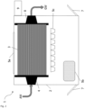
- Figure 1 shows a front view of a device 1 according to the invention, that is, a head view of the housing 2, which in preferred embodiments of the invention is formed from a shipping container, in particular a 40-foot shipping container (with dimensions of 12200 mm x 2400 mm x 2600 mm).
- a shipping container in particular a 40-foot shipping container (with dimensions of 12200 mm x 2400 mm x 2600 mm).
- This translucent side element 5a is normally designed as one or more windows; however, it is also possible to use a larger translucent plate, for example made of Plexiglas.
- Translucent ceiling elements 5b can also be present in the housing ceiling.
- FIG. 1 a variant of the present invention is shown in which the cultivation surfaces 3 are arranged in only one half of the housing 2 (here on the left).
- the cultivation surfaces 3 in this figure only take up about a third of the width (which is purely illustrative), the cultivation surfaces 3 can of course also take up more or less width than shown in the figure, or even the entire width (which is often not desired, since then easy access to the housing 2 or to the cultivation surfaces 3 is no longer guaranteed; in this respect, at least a small part of the width will usually remain free as a passage/access).
- the present invention is also not limited to the five cultivation surfaces 3 shown arranged one above the other; there can of course be more or fewer.
- a feed device for water to be treated 4 is also shown, by means of which water to be treated (waste water) AW is distributed to the individual cultivation surfaces 3 .
- Water to be treated (wastewater) AW is supplied from the outside, illustrated here by a spotted arrow, for example via a suitable wastewater inlet such as a hose or a gutter (not shown).
- a suitable wastewater inlet such as a hose or a gutter (not shown).
- a (dirt) pump which can be arranged (outside) at the head end of the housing (container).
- the housing has ventilation devices, which are shown here as ventilation holes 6 ; instead of simple holes, however, mechanically and/or electronically supported ventilation devices can also be present. Ideally (for better air circulation) these are located on or on the bottom and top of the housing 2. Approximately in the middle of the interior of the housing 2, further devices for supplying light are shown in the form of lamps 5c ; these can in particular be LED lamps, which can be suspended laterally, for example, which is not visible in the figure perspective. Furthermore, a door is indicated in the figure by means of a dashed line, as a preferred embodiment of an openable and closable access 7. Furthermore, a discharge device for treated water 8 is indicated by means of dashed lines, which is located at the other end of the housing.
- the window and also the cultivation area are shown on the left. This is preferred but not necessarily always the case - because it is preferred if the cultivation area is arranged directly next to the (one) window so that the cultivation areas, and thus the biofilms, receive sufficient light; however, this can be deviated from, especially if lamps 5c and/or translucent elements 5b are present.
- Figure 2 shows a top view of the same housing 2 as Figure 1 . Shown here is the same supply device for water to be treated 4 with inflow of water to be treated AW, as in Figure 1 and at the other end of the cultivation areas 3 (of which only the top one can be seen due to the perspective) there is the discharge device for treated water 8.
- the purified water GW is then discharged to the outside in some variants (shown here by a spotted arrow). It is also possible to circulate the purified water and feed it back to the cultivation areas 3 to enable further purification; however, this is not usually the case. It is also possible to temporarily store the purified water in a collection container until it is released, for example until it has been tested and processed in accordance with legal or operational requirements.
- the lamps 5c can be seen in their lateral arrangement in this illustration, as well as the translucent side element 5a.
- Figure 2 Another, optional, translucent ceiling element 5b is shown (of which one, several or none at all may be present). Similar to Figure 1 Openable and closable accesses 7 are indicated by a dashed line.
- Electronic/hydraulic operating devices 9 are in Figure 2 shown arranged externally, but in some preferred variants of the present invention they are arranged inside the housing, since this variant simplifies the transportability of the entire device 1 .
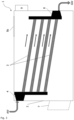
- Figure 3 shows a side view of the same device 1.
- the inclination angles of the cultivation areas 3 shown are shown for better illustration and do not necessarily correspond to the angles used in reality.
- the four arrows arranged above the respective cultivation areas 3 indicate the flow direction of the water to be treated over the cultivation areas 3 or the (microalgae) biofilms located thereon.
- the feed device for water to be treated 4 with inflow of water to be treated AW, and at the other end of the cultivation areas 3 the discharge device for treated water 8 , and in the variant shown the purified water GW is discharged to the outside.
- the water inlet of the feed device 4 is arranged higher than the uppermost cultivation area 3 and the water outlet of the discharge device 8 is lower than the lowermost cultivation area 3; in this way the water transport or the water flow takes place according to gravity and does not require any additional energy-intensive help from pumps, for example.
- the feed and discharge devices for the water are designed as a distributor on the one hand and as a collector on the other. However, within the scope of the present invention it is also possible to provide several feed and discharge devices, for example for some cultivation areas and/or for individual cultivation areas; as required.
- Figure 4 shows the data of Table 1 as a diagram, showing the percentage of the different elements (K, N, P, C and rest) in the total mass.
Landscapes
- Life Sciences & Earth Sciences (AREA)
- Engineering & Computer Science (AREA)
- Biotechnology (AREA)
- Botany (AREA)
- Biodiversity & Conservation Biology (AREA)
- Microbiology (AREA)
- Hydrology & Water Resources (AREA)
- Environmental & Geological Engineering (AREA)
- Water Supply & Treatment (AREA)
- Chemical & Material Sciences (AREA)
- Organic Chemistry (AREA)
- Biological Treatment Of Waste Water (AREA)
Applications Claiming Priority (1)
| Application Number | Priority Date | Filing Date | Title |
|---|---|---|---|
| DE102023116102.4A DE102023116102A1 (de) | 2023-06-20 | 2023-06-20 | Mikroalgenbiofilmreaktor |
Publications (1)
| Publication Number | Publication Date |
|---|---|
| EP4480930A1 true EP4480930A1 (fr) | 2024-12-25 |
Family
ID=91539801
Family Applications (1)
| Application Number | Title | Priority Date | Filing Date |
|---|---|---|---|
| EP24181977.0A Pending EP4480930A1 (fr) | 2023-06-20 | 2024-06-13 | Réacteur à biofilm de microalgues |
Country Status (2)
| Country | Link |
|---|---|
| EP (1) | EP4480930A1 (fr) |
| DE (1) | DE102023116102A1 (fr) |
Citations (11)
| Publication number | Priority date | Publication date | Assignee | Title |
|---|---|---|---|---|
| US4333263A (en) | 1980-10-07 | 1982-06-08 | The Smithsonian Institution | Algal turf scrubber |
| WO1996013970A1 (fr) | 1994-11-08 | 1996-05-17 | Ecological Systems, Inc. | Procede d'epuration d'eau au moyen d'un tapis d'algue |
| US20070155006A1 (en) | 2005-12-30 | 2007-07-05 | Alexander Levin | Photobioreactor |
| DE102009016738A1 (de) | 2009-04-09 | 2010-10-14 | Salata Gmbh | Photobioreaktor sowie Verfahren zur Kultivation von Biomasse mittels Photosynthese |
| WO2014085869A1 (fr) | 2012-12-07 | 2014-06-12 | James Cook University | Bioréacteur et procédé d'utilisation |
| AU2012339628A1 (en) * | 2011-11-15 | 2014-07-10 | Advanced Algal Technologies Limited | A system for growing one or more biological organisms |
| WO2014172691A1 (fr) | 2013-04-18 | 2014-10-23 | Higgs Daniel | Procédés et système de conversion solaire |
| WO2015087169A2 (fr) | 2013-12-13 | 2015-06-18 | Algabloom International Ltd. | Bioréacteurs supportés dans un châssis à claies et procédés de culture de micro-organismes les utilisant |
| DE102014000691A1 (de) | 2014-01-17 | 2015-07-23 | Forschungszentrum Jülich GmbH Fachbereich Patente | Photobioreaktor und Verfahren zur Dünnschichtkultivierung |
| DE202019005811U1 (de) | 2019-02-05 | 2022-08-18 | Solaga UG (haftungsbeschränkt) | Bioreaktor für stationäre Biofilme aus photosynthetisch aktiven Mikroorganismen |
| WO2024038269A1 (fr) | 2022-08-17 | 2024-02-22 | A Healthier Earth Limited | Culture d'organismes aquatiques, ainsi que d'algues, en particulier pour favoriser la conversion du co2 en biomasse |
-
2023
- 2023-06-20 DE DE102023116102.4A patent/DE102023116102A1/de active Pending
-
2024
- 2024-06-13 EP EP24181977.0A patent/EP4480930A1/fr active Pending
Patent Citations (11)
| Publication number | Priority date | Publication date | Assignee | Title |
|---|---|---|---|---|
| US4333263A (en) | 1980-10-07 | 1982-06-08 | The Smithsonian Institution | Algal turf scrubber |
| WO1996013970A1 (fr) | 1994-11-08 | 1996-05-17 | Ecological Systems, Inc. | Procede d'epuration d'eau au moyen d'un tapis d'algue |
| US20070155006A1 (en) | 2005-12-30 | 2007-07-05 | Alexander Levin | Photobioreactor |
| DE102009016738A1 (de) | 2009-04-09 | 2010-10-14 | Salata Gmbh | Photobioreaktor sowie Verfahren zur Kultivation von Biomasse mittels Photosynthese |
| AU2012339628A1 (en) * | 2011-11-15 | 2014-07-10 | Advanced Algal Technologies Limited | A system for growing one or more biological organisms |
| WO2014085869A1 (fr) | 2012-12-07 | 2014-06-12 | James Cook University | Bioréacteur et procédé d'utilisation |
| WO2014172691A1 (fr) | 2013-04-18 | 2014-10-23 | Higgs Daniel | Procédés et système de conversion solaire |
| WO2015087169A2 (fr) | 2013-12-13 | 2015-06-18 | Algabloom International Ltd. | Bioréacteurs supportés dans un châssis à claies et procédés de culture de micro-organismes les utilisant |
| DE102014000691A1 (de) | 2014-01-17 | 2015-07-23 | Forschungszentrum Jülich GmbH Fachbereich Patente | Photobioreaktor und Verfahren zur Dünnschichtkultivierung |
| DE202019005811U1 (de) | 2019-02-05 | 2022-08-18 | Solaga UG (haftungsbeschränkt) | Bioreaktor für stationäre Biofilme aus photosynthetisch aktiven Mikroorganismen |
| WO2024038269A1 (fr) | 2022-08-17 | 2024-02-22 | A Healthier Earth Limited | Culture d'organismes aquatiques, ainsi que d'algues, en particulier pour favoriser la conversion du co2 en biomasse |
Non-Patent Citations (4)
| Title |
|---|
| D. REINECKE ET AL., SEPARATION AND PURIFICATION TECHNOLOGY, vol. 305, 2023, pages 122471 |
| IST D. REINECKE ET AL.: "Nutrient recovery from wastewater by algal biofilm fertilizer production part 1: Case study on the techno-economical aspects at pilot-scale", SEPARATION AND PURIFICATION TECHNOLOGY, vol. 305, 2023, pages 122471 |
| POSADAS ESTHER ET AL: "Enclosed tubular and open algal-bacterial biofilm photobioreactors for carbon and nutrient removal from domestic wastew", ECOLOGICAL ENGINEERING, ELSEVIER, AMSTERDAM, NL, vol. 67, 4 May 2014 (2014-05-04), pages 156 - 164, XP029025127, ISSN: 0925-8574, DOI: 10.1016/J.ECOLENG.2014.03.007 * |
| SINGH GULAB ET AL: "Development and Applications of Attached Growth System for Microalgae Biomass Production", BIOENERGY RESEARCH, SPRINGER US, BOSTON, vol. 14, no. 3, 28 September 2020 (2020-09-28), pages 709 - 722, XP037554052, ISSN: 1939-1234, [retrieved on 20200928], DOI: 10.1007/S12155-020-10195-8 * |
Also Published As
| Publication number | Publication date |
|---|---|
| DE102023116102A1 (de) | 2024-12-24 |
Similar Documents
| Publication | Publication Date | Title |
|---|---|---|
| DE69030976T2 (de) | Prozess und apparatur zur produktion von photosynthetisierenden mikroben | |
| EP2417243B1 (fr) | Photobioréacteurs et procédé pour la culture de biomasse par la photosynthèse | |
| DE4224554C2 (de) | Verfahren zum Aufziehen von Fischen | |
| AT517667B1 (de) | Verfahren zur Gewinnung von entfeuchteter Biomasse | |
| DE102018123378A1 (de) | Torfmooswand | |
| WO2011018082A2 (fr) | Procédé et dispositif de production de biomasse | |
| EP1748960A1 (fr) | Station d'epuration de type vegetal pour epurer des eaux usees | |
| EP4480930A1 (fr) | Réacteur à biofilm de microalgues | |
| DE202019106334U1 (de) | Kreislaufkultursystem, Verwenden eines Kreislaufkultursystems | |
| DE102015013574A1 (de) | Plattform zur bakteriellen nitrifikaton von wasser und/oder zum anbau erdloser pflanzenkulturen über wasserflächen und feuchtgebieten | |
| DE102012011409B4 (de) | Verfahren zur Wasserbehandlung mit Pflanzenanlagen und Verwendungen des Verfahrens | |
| EP2417242B1 (fr) | Dispositif et procédé d'élimination de co2, et utilisations | |
| EP3015157B1 (fr) | Filtre et systeme de filtre | |
| DE3921241C1 (fr) | ||
| EP3557974A1 (fr) | Unité agricole, module agricole, système agricole et procédé destiné au fonctionnement d'un système agricole | |
| DE102010017097B4 (de) | Trocknungsanlage für Biomasse und/oder Schlämme | |
| EP2100856B1 (fr) | Procédé de traitement biologique de l'eau | |
| EP4236675A1 (fr) | Système de culture modulaire et procédé de culture d'organismes procaryotes et/ou eucaryotes | |
| DE102020125591B4 (de) | Technische Anlage zur industriellen Zucht der Alge Cladophora glomerata sowie Verwendung dieser Anlage zur Abwasserreinigung, Entsorgung von Brüdenkondensat, Reinigung von Klärschlammasche, Phosphorrückgewinnung und/oder Biogasproduktion sowie Verwendung der Alge Cladophora glomerata zur Abwasserreinigung | |
| WO2020038896A1 (fr) | Dispositif et procédé permettant simultanément l'épuration biologique d'eaux usées, en particulier d'eaux usées comprenant une charge polluante biologiquement dégradable, et la fourniture d'air refroidi | |
| DE102012024463A1 (de) | Verfahren und Einrichtung zur Abwasser- oder Prozesswasserbehandlung, oder Prozesswasserbehandlung aus der hydrothermalen Karbonisierung | |
| DE102010018431B4 (de) | Verfahren und Vorrichtung zur Sterilisation von Erde zur Anpflanzung von koreanischem Ginseng | |
| DE102022100209B4 (de) | Photobioreaktor zur Lebenderhaltung von Algen mit von außen beleuchteten Fächern | |
| AT523817A2 (de) | Bioreaktor für stationäre Biofilme aus photosynthetisch aktiven Mikroorganismen | |
| DE102008016116A1 (de) | Bioreaktor und Verfahren zum Betreiben eines Bioreaktors |
Legal Events
| Date | Code | Title | Description |
|---|---|---|---|
| PUAI | Public reference made under article 153(3) epc to a published international application that has entered the european phase |
Free format text: ORIGINAL CODE: 0009012 |
|
| STAA | Information on the status of an ep patent application or granted ep patent |
Free format text: STATUS: THE APPLICATION HAS BEEN PUBLISHED |
|
| AK | Designated contracting states |
Kind code of ref document: A1 Designated state(s): AL AT BE BG CH CY CZ DE DK EE ES FI FR GB GR HR HU IE IS IT LI LT LU LV MC ME MK MT NL NO PL PT RO RS SE SI SK SM TR |
|
| STAA | Information on the status of an ep patent application or granted ep patent |
Free format text: STATUS: REQUEST FOR EXAMINATION WAS MADE |
|
| 17P | Request for examination filed |
Effective date: 20250306 |