EP4481145A1 - Clé, serrure et système de clé et serrure associé - Google Patents
Clé, serrure et système de clé et serrure associé Download PDFInfo
- Publication number
- EP4481145A1 EP4481145A1 EP24180603.3A EP24180603A EP4481145A1 EP 4481145 A1 EP4481145 A1 EP 4481145A1 EP 24180603 A EP24180603 A EP 24180603A EP 4481145 A1 EP4481145 A1 EP 4481145A1
- Authority
- EP
- European Patent Office
- Prior art keywords
- key
- lock
- rotor
- flat
- discontinuity
- Prior art date
- Legal status (The legal status is an assumption and is not a legal conclusion. Google has not performed a legal analysis and makes no representation as to the accuracy of the status listed.)
- Pending
Links
Images


Classifications
-
- E—FIXED CONSTRUCTIONS
- E05—LOCKS; KEYS; WINDOW OR DOOR FITTINGS; SAFES
- E05B—LOCKS; ACCESSORIES THEREFOR; HANDCUFFS
- E05B19/00—Keys; Accessories therefor
- E05B19/0017—Key profiles
- E05B19/0041—Key profiles characterized by the cross-section of the key blade in a plane perpendicular to the longitudinal axis of the key
- E05B19/0047—Key profiles characterized by the cross-section of the key blade in a plane perpendicular to the longitudinal axis of the key with substantially circular or star-shape cross-section
-
- E—FIXED CONSTRUCTIONS
- E05—LOCKS; KEYS; WINDOW OR DOOR FITTINGS; SAFES
- E05B—LOCKS; ACCESSORIES THEREFOR; HANDCUFFS
- E05B27/00—Cylinder locks or other locks with tumbler pins or balls that are set by pushing the key in
- E05B27/0003—Details
- E05B27/0007—Rotors
-
- E—FIXED CONSTRUCTIONS
- E05—LOCKS; KEYS; WINDOW OR DOOR FITTINGS; SAFES
- E05B—LOCKS; ACCESSORIES THEREFOR; HANDCUFFS
- E05B27/00—Cylinder locks or other locks with tumbler pins or balls that are set by pushing the key in
- E05B27/0042—Cylinder locks or other locks with tumbler pins or balls that are set by pushing the key in with additional key identifying function, e.g. with use of additional key operated rotor-blocking elements, not of split pin tumbler type
-
- E—FIXED CONSTRUCTIONS
- E05—LOCKS; KEYS; WINDOW OR DOOR FITTINGS; SAFES
- E05B—LOCKS; ACCESSORIES THEREFOR; HANDCUFFS
- E05B27/00—Cylinder locks or other locks with tumbler pins or balls that are set by pushing the key in
- E05B27/0053—Cylinder locks or other locks with tumbler pins or balls that are set by pushing the key in for use with more than one key, e.g. master-secondary key
-
- E—FIXED CONSTRUCTIONS
- E05—LOCKS; KEYS; WINDOW OR DOOR FITTINGS; SAFES
- E05B—LOCKS; ACCESSORIES THEREFOR; HANDCUFFS
- E05B35/00—Locks for use with special keys or a plurality of keys ; keys therefor
- E05B35/08—Locks for use with special keys or a plurality of keys ; keys therefor operable by a plurality of keys
- E05B35/10—Locks for use with special keys or a plurality of keys ; keys therefor operable by a plurality of keys with master and pass keys
Definitions
- the present invention refers to a key, a lock, and a related key and lock system, in particular a master key key and lock system, which allows in a simple, reliable, safe, efficient and economical way to create systems with master key.
- a so-called master key system of keys and locks includes a group of locks distinct from each other, each operated in closing and opening by a respective key, in which a single key, called master key, is configured to operate in closing and opening all the system locks.
- master key systems are applied in hotels, for example for rooms on the same floor, in which there is a group of keys each configured to operate a respective lock, mounted on the entrance door of a corresponding room, and a master key configured to operate all the locks mounted on the entrance doors of the rooms on the floor, typically used by the domestic worker to access each of the rooms on the floor.
- the hierarchical structure of the keys of a master key system can be extended to multiple levels, so a group of master keys can in turn have one or more superior master keys.
- a second type of prior art master key systems uses specific key profiles in which each key of the system has a different cross section from that of the other keys and can consequently only fit into a respective lock, while the master key of the system, known as a master key, has a cross section configured to enter and operate all locks in the system.
- This second type of prior art master key systems is very expensive as it requires keys and locks with peculiar processes.
- a third type of prior art master key systems applied in very complex facilities, such as universities and hospitals, consists of a combination of the first two types of prior art master key systems illustrated above.
- the aim of the present invention is to allow master key systems with high security to be created in a simple, reliable, efficient and economical way.
- the specific object of the present invention is a key having a longitudinally extending actuating element provided with one or more blades which protrude longitudinally and orthogonally from the actuating element, wherein the actuating element describes a portion of cylindrical surface whose distal end is a an arc of a circle, whereby the actuating member defines an open channel, wherein the actuating member is configured to fit into a corresponding slot of a lock rotor and said one or more blades are each configured for interacting with pins housed in a respective longitudinal row of rotor chambers when the actuating member is inserted of said lock, wherein the actuating member has a flat proximal retaining surface, which is opposite the distal end and disposed internally to said open channel, wherein the flat proximal retaining surface is provided with at least a first discontinuity element, wherein when the actuating element is inserted into the corresponding slot of the rotor at the actuation position:
- said at least one first discontinuity element may consist of a single first discontinuity element.
- said at least one first discontinuity element can be a longitudinal hole configured to receive a corresponding longitudinal protruding pin of the corresponding external stop surface of said lock.
- said at least one first discontinuity element can be a longitudinal protruding pin configured to fit into a corresponding longitudinal hole of the corresponding external stop surface of said lock.
- said one or more blades can consist of three blades spaced angularly apart from each other by 90° with respect to a longitudinal axis of the actuating element.
- the angle delimiting the an arc of a circle of the distal end of the actuating element can be greater than 270°, optionally greater than 300°.
- a specific object of the present invention is also a lock comprising a rotor housed inside a stator, in which the rotor is provided with a slot defined by a core having two ends and fixed inside the rotor, in which the slot is configured to receive a key actuation member as precedingly described, wherein the rotor is provided with one or more rows of rotor chambers each of which rows of rotor chambers accommodate pins configured to interact with a respective blade of said one or multiple key blades, wherein at least one of the two ends of the core has a flat outer stop surface which is provided with at least a second discontinuity element, wherein when the actuating element is inserted into the corresponding slot of the rotor at the position drive:
- Said at least one second discontinuity element can be a longitudinal protruding pin configured to fit into a corresponding longitudinal hole of the corresponding flat proximal retaining surface of the key, or said at least one second discontinuity element can be a longitudinal hole configured to receive a corresponding longitudinal protruding pin of the corresponding flat proximal retaining surface of the key.
- a specific object of the present invention is a key and lock system, comprising at least one lock as described above and at least one corresponding key as precedingly described, in which the stator of said at least one lock is provided with one or more rows of stator chambers each of which rows of stator chambers houses counter-pins pushed by respective springs and which in turn push the pins towards the rotor chambers, wherein the rotor of said at least one lock is configured to rotate inside the stator of said at least one lock when the pins and counterpins align in an opening configuration when the rotor slot of said at least one lock receives the operating element of said at least one corresponding key at the operating position.
- the key and lock system may be a master key system.
- the key and lock system according to the invention advantageously applicable to armored doors, offers numerous advantages.
- system according to the invention uses a key equipped with encryption with very high resistance to break-in.
- the lock comprises a rotor 10, which has a cylindrical shape, housed inside a stator 20, which has the shape of a hollow cylinder.
- the rotor 10 is provided with a slot 15, defined by a core or core 40 conventionally fixed inside the rotor 10 by means of a pin 45; the slot 15 is configured to receive a key 30.
- the rotation of the rotor 10 inside the stator 20 is conventionally prevented by a plurality of pins 22A, 22B and 22C of various lengths arranged radially and housed in respective chambers 14A and 14B, 14C arranged radially on the rotor 10, and possibly in respective chambers 24A, and 24B and 24C arranged radially on the stator 20, arranged along three longitudinal rows spaced angularly apart from each other by 90° with respect to the longitudinal axis of the rotor 10 and the stator 20.
- the pins 22A, 22B and 22C are conventionally pushed towards the inside of the chambers 14A, 14B and 14C of the rotor 10 by respective counter pins 26A, 26B and 26C pushed in turn by respective springs 28A, 28B and 28C.
- the key 30 has a longitudinally extending actuating element 32 provided with three blades 35A, 35B and 35C which project longitudinally and orthogonally from the actuating element 32.
- the actuating element 32 describes a portion of cylindrical surface, whose distal end 37, configured to be inserted into the slot 15 of the rotor 10, has a transverse profile which is a an arc of a circle delimited by an angle greater than 270°, advantageously greater of 300°, on which the three blades 35A, 35B and 35C are spaced angularly apart from each other by 90°, with respect to the longitudinal axis of the drive element 32.
- the three blades 35A, 35B and 35C are configured to interact each conventionally with the pins 22A, 22B and 22C housed in a respective row of the chambers 14A, 14B and 14C of the rotor 10: in particular, by inserting the key 30 into the rotor 10, the blades 35A, 35B and 35C, provided with notches of variable depth, interact with the pins 22A, 22B and 22C in such a way that pins 22A, 22B and 22C and counter-pins 26A, 26B and 26C align in an opening configuration wherein the pins 22A, 22B and 22C are entirely housed inside the chambers 14A, 14B and 14C of the rotor 10, while the counter pins 26A, 26B and 26C are entirely housed inside the chambers 24A, 24B and 24C of the stator 20, thus allowing the rotation of the rotor 10 inside the stator 20.
- the lengths of the pins 22A, 22B and 22C correspond to the depths of the notches of the respective blades 35A, 35B and 35C; in this regard, the notches of the blades 35A, 35B and 35C constitute the encryption of the key 30.
- the correct position for inserting the key 30 inside the rotor 10 in order to obtain the alignment of the pins 22A, 22B and 22C and counter-pins 26A, 26B and 26C is defined by the contact of an entirely planar proximal retaining surface 38 of the key 30, which is opposite to the distal end 37 and arranged internally to the open channel defined by the drive element 32, with a corresponding entirely planar external stop surface 48 of the core 40 fixed inside the rotor 10.
- any incorrect positioning of the element 32 for operating the key 30 in the slot 15 of the rotor 10 would result in a failure to correctly align the pins 22A, 22B and 22C and the counter-pins 26A, 26B and 26C which would consequently not assume the opening configuration, keeping the lock locked since the rotor 10 could not rotate inside the stator 20.
- the key 30 must also have the coding corresponding to the pins 22A, 22B and 22C.
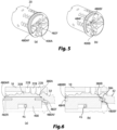
- a first embodiment of the key according to the invention differs from the key 30 of Figures 1-3 in that the flat proximal retaining surface 380A of the key 300A is provided with a longitudinal hole 382 configured to receive a corresponding pin.
- the key 300A is configured to be inserted into a first embodiment of the lock according to the invention, shown in Figure 5a , which differs from the lock of Figures 1-3 in that the core 400A, fixed inside of the rotor 10, has a flat external stop surface 480AF provided with a protruding longitudinal pin 482F configured to be inserted into the longitudinal hole 382 of the flat proximal stop surface 380A of the key 300A.
- Figure 6a shows the actuating element 32 of the key 300A inserted into the slot 15 of the rotor 10 up to the position wherein the flat proximal stop surface 380A of the key 300A comes into contact with the corresponding flat external stop surface 480AF of the core 400A and the protruding longitudinal pin 482F of the flat external stop surface 480AF of the core 400A fits into the longitudinal hole 382 of the flat proximal stop surface 380A of the key 300A, blocking the further advancement of the actuating element 32 in the slot 15 of the rotor 10 and allowing the notches of the blades 35A, 35B and 35C of the key 300A to interact with the pins 22A, 22B and 22C thus obtaining the alignment of pins 22A, 22B and 22C and counter pins 26A, 26B and 26C, similarly to what is shown in Figure 3 .
- the first embodiment of the lock according to the invention can be operated by the same key 300A in the same way from both sides, therefore, as shown in Figure 6a , also the other end of the core 400A has a flat external stop surface 480AR provided with a protruding longitudinal pin 482R configured to be inserted into the longitudinal hole 382 of the flat proximal stop surface 380A of the key 300A; obviously, the notches of the blades 35A, 35B and 35C are also shaped so as to interact correctly with the pins 22A, 22B and 22C even when the drive element 32 is inserted into the other side of the slot 15 of the rotor 10.
- a second embodiment of the key according to the invention differs from the key 30 of Figures 1-3 in that the flat proximal retaining surface 380B of the key 300B is provided with a protruding longitudinal pin 384 configured to be inserted into a corresponding hole.
- the key 300B is configured to be inserted into a second embodiment of the lock according to the invention, shown in Figure 5b , which differs from the lock of Figures 1-3 in that the core 400B, fixed inside of the rotor 10, has a flat external stop surface 480BF provided with a longitudinal hole 484F configured to receive the protruding longitudinal pin 384 of the flat proximal stop surface 380B of the key 300B.
- Figure 6b shows the actuating element 32 of the key 300B inserted into the slot 15 of the rotor 10 up to the position wherein the flat proximal stop surface 380B of the key 300B comes into contact with the corresponding flat external stop surface 480BF of the core 400B and the protruding longitudinal pin 384 of the flat proximal stop surface 380B of the key 300B fits into the longitudinal hole 484F of the flat external stop surface 480BF of the core 400B, blocking the further advancement of the actuating element 32 in the slot 15 of the rotor 10 and allowing the notches of the blades 35A, 35B and 35C of the key 300B to interact with the pins 22A, 22B and 22C thus obtaining the alignment of pins 22A, 22B and 22C and counter pins 26A, 26B and 26C, similarly to what is shown in Figure 3 .
- the second embodiment of the lock according to the invention can also be operated by the same key 300B in the same way from both sides, therefore, as shown in Figure 6b , also the other end of the core 400B has a flat external stop surface 480BR provided with a longitudinal hole 484R configured to receive the protruding longitudinal pin 384 of the flat proximal stop surface 380B of the key 300B; obviously, the notches of the blades 35A, 35B and 35C are also shaped so as to interact correctly with the pins 22A, 22B and 22C even when the drive element 32 is inserted into the other side of the slot 15 of the rotor 10.
- the first embodiment of the key according to the invention is a female version, wherein the flat proximal retaining surface 380A of the key 300A is provided with a longitudinal hole 382, while the second embodiment of the key according to the The invention is a male version, wherein the flat proximal retaining surface 380A of the key 300A is provided with a longitudinal protruding pin 384.
- the first embodiment of the lock according to the invention is a male version, wherein the flat external stop surface 480AF of the core 400A is provided with a longitudinal protruding pin 482F
- the second embodiment of the lock according to the invention is a female version, wherein the flat external stop surface 480AF of the core 400A is provided with a longitudinal hole 484F.
- the flat proximal surface, 380A or 380B, holding the key, 300A or 300B, according to the invention is provided with a first discontinuity element, wherein this first discontinuity element is a longitudinal hole 382 or a pin longitudinal projection 384; in particular, the first discontinuity element can be entirely or partially surrounded by the flat proximal surface.
- the first discontinuity element, 382 or 384, of the flat proximal surface, 380A or 380B, holding the key, 300A or 300B, according to the invention is configured to interact, in particular to couple in a removable way, with a corresponding second discontinuity element discontinuity of the flat external stop surface, 480AF or 480BF, of the core 400A or 400B, fixed inside the rotor 10 of the lock according to the invention; this corresponding second discontinuity element can also be entirely or partially surrounded by the flat proximal stop surface, 480AF or 480BF, of the core, 400A or 400B.
- this second discontinuity element is a longitudinal protruding pin 482F when the first discontinuity element is a longitudinal hole 382, while it is a longitudinal hole 484F when the first discontinuity element is a longitudinal protruding pin 384.
- the key and lock according to the invention allow the creation of a master key system, even at two levels.
- the key 300B of Figure 4b is configured to operate only the lock of Figure 5b , not being able to operate the lock of Figure 5a or the lock of Figure 2b , wherein the external stop surface 48 of the core 40 is entirely planar, ie free of holes and protruding pins.
- the key 300A of Figure 4a is configured to operate the lock of Figure 5a , the lock of Figure 5b , and also the lock of Figure 2b .
- the key 30 of Figures 1 and 2c wherein the proximal latch surface 38 is entirely planar, i.e. free of protruding holes and pins, is configured to operate the lock of Figure 5b and the lock of Figure 2b , but cannot operate the lock of Figure 5a .
- embodiments of the key and lock according to the invention may have the flat proximal retaining surface of the key which is provided with a plurality of first discontinuity elements, comprising longitudinal holes and/or pins longitudinal, each of which is configured to interact, in particularto couple in a removable way, with a respective corresponding second element of discontinuity of the flat external stop surface of the core, fixed inside the rotor 10 of the lock, so that also the surface external flat stop of the core is provided with a plurality of second discontinuity elements, therefore comprising longitudinal pins and/or longitudinal holes.
- the first discontinuity elements can be entirely or partially surrounded by the flat proximal surface; the second discontinuity elements can be entirely or partially surrounded by the flat external surface.
- the master key system according to the invention as a system wherein the element 32 for operating the key, or a single key, is configured to be inserted into a corresponding slot 15 of a rotor 10 of a plurality of locks, and when the operating element 32 is inserted into the corresponding slot 15 of the rotor 10 of a lock of the plurality of locks, in the operating position:
- further embodiments of the key and lock according to the invention may have a number of blades protruding from the actuating element 32, and a corresponding number of longitudinal rows of chambers arranged radially on the rotor 10 and of chambers arranged radially on the stator 20, which house pins, respective counter-pins and respective springs, different from three, for example one, two or more than three, always remaining within the scope of protection of the present invention.
Landscapes
- Lock And Its Accessories (AREA)
Applications Claiming Priority (1)
| Application Number | Priority Date | Filing Date | Title |
|---|---|---|---|
| IT102023000012789A IT202300012789A1 (it) | 2023-06-21 | 2023-06-21 | Chiave, serratura e relativo sistema di chiave e serratura |
Publications (1)
| Publication Number | Publication Date |
|---|---|
| EP4481145A1 true EP4481145A1 (fr) | 2024-12-25 |
Family
ID=88097346
Family Applications (1)
| Application Number | Title | Priority Date | Filing Date |
|---|---|---|---|
| EP24180603.3A Pending EP4481145A1 (fr) | 2023-06-21 | 2024-06-06 | Clé, serrure et système de clé et serrure associé |
Country Status (3)
| Country | Link |
|---|---|
| EP (1) | EP4481145A1 (fr) |
| IL (1) | IL313720A (fr) |
| IT (1) | IT202300012789A1 (fr) |
Citations (6)
| Publication number | Priority date | Publication date | Assignee | Title |
|---|---|---|---|---|
| US2620649A (en) * | 1948-02-18 | 1952-12-09 | Bernardo Vicente Santo Domingo | Pin tumbler lock |
| US4148201A (en) | 1975-11-22 | 1979-04-10 | Sanpo Lock Co., Ltd. | Locking device |
| GB1578559A (en) * | 1977-05-20 | 1980-11-05 | Chung Cheng Ku | Construction for a cylinder lock and key |
| EP3219882A1 (fr) | 2016-03-16 | 2017-09-20 | Assa Ab | Serrure à barillet et système de clé |
| CN108131054A (zh) | 2018-03-02 | 2018-06-08 | 宿迁顾师傅锁业有限公司 | 一种智能锁的锁芯及其多边形钥匙 |
| EP3425141A1 (fr) * | 2017-07-07 | 2019-01-09 | Mottura Serrature di Sicurezza S.p.A. | Verrou de sécurité |
-
2023
- 2023-06-21 IT IT102023000012789A patent/IT202300012789A1/it unknown
-
2024
- 2024-06-06 EP EP24180603.3A patent/EP4481145A1/fr active Pending
- 2024-06-19 IL IL313720A patent/IL313720A/en unknown
Patent Citations (6)
| Publication number | Priority date | Publication date | Assignee | Title |
|---|---|---|---|---|
| US2620649A (en) * | 1948-02-18 | 1952-12-09 | Bernardo Vicente Santo Domingo | Pin tumbler lock |
| US4148201A (en) | 1975-11-22 | 1979-04-10 | Sanpo Lock Co., Ltd. | Locking device |
| GB1578559A (en) * | 1977-05-20 | 1980-11-05 | Chung Cheng Ku | Construction for a cylinder lock and key |
| EP3219882A1 (fr) | 2016-03-16 | 2017-09-20 | Assa Ab | Serrure à barillet et système de clé |
| EP3425141A1 (fr) * | 2017-07-07 | 2019-01-09 | Mottura Serrature di Sicurezza S.p.A. | Verrou de sécurité |
| CN108131054A (zh) | 2018-03-02 | 2018-06-08 | 宿迁顾师傅锁业有限公司 | 一种智能锁的锁芯及其多边形钥匙 |
Also Published As
| Publication number | Publication date |
|---|---|
| IT202300012789A1 (it) | 2024-12-21 |
| IL313720A (en) | 2025-01-01 |
Similar Documents
| Publication | Publication Date | Title |
|---|---|---|
| EP0617184B1 (fr) | Combinaison d'une serrure de cylindre avec une clé | |
| JP5400181B2 (ja) | シリンダ錠と鍵との組合体 | |
| EP0605932B1 (fr) | Dispositif de verrouillage | |
| US7424815B1 (en) | Reprogrammable lock | |
| EP2899337B1 (fr) | Système de verrouillage | |
| US6718807B2 (en) | Lock device with removable core | |
| US9598880B2 (en) | Lock cylinder including modular plug | |
| HU222413B1 (hu) | Programozható cilinderzár mesterkulcsokkal | |
| CN115637895A (zh) | 具有小增量的可重设锁 | |
| KR20130041318A (ko) | 잠금 장치 | |
| EP1772576B1 (fr) | Système de serrure cylindrique et jeu de clés | |
| JP2026040815A (ja) | 施錠装置及び解錠鍵、並びにドア | |
| EP4481145A1 (fr) | Clé, serrure et système de clé et serrure associé | |
| EP2453084A2 (fr) | Serrure à barillet fonctionnant avec une clé rotative | |
| EP1752601A2 (fr) | Verrou reprogrammable | |
| EP3103944A9 (fr) | Clé avec un élément pivotant et un verrou | |
| NZ531836A (en) | Lock with cylinder incorporating laterally biased bar engaging corresponding key | |
| EP2990567B1 (fr) | Noyau de serrure cylindrique et verrou pourvu d'un tel noyau | |
| CN121752793A (zh) | 盘形弹子圆柱锁与钥匙的组合结构 | |
| RU2648617C1 (ru) | Замок | |
| EP3891352B1 (fr) | Unité de serrure à barillet et clé associée | |
| EP0078280B1 (fr) | Mecanismes fonctionnant avec une cle pour serrures | |
| AU2013204413A1 (en) | Lock system | |
| HK1005558B (en) | Cylinder lock-key-combination | |
| KR20040078332A (ko) | 로터리 디스크 텀블러 자물쇠 및 열쇠 |
Legal Events
| Date | Code | Title | Description |
|---|---|---|---|
| PUAI | Public reference made under article 153(3) epc to a published international application that has entered the european phase |
Free format text: ORIGINAL CODE: 0009012 |
|
| STAA | Information on the status of an ep patent application or granted ep patent |
Free format text: STATUS: THE APPLICATION HAS BEEN PUBLISHED |
|
| AK | Designated contracting states |
Kind code of ref document: A1 Designated state(s): AL AT BE BG CH CY CZ DE DK EE ES FI FR GB GR HR HU IE IS IT LI LT LU LV MC ME MK MT NL NO PL PT RO RS SE SI SK SM TR |
|
| STAA | Information on the status of an ep patent application or granted ep patent |
Free format text: STATUS: REQUEST FOR EXAMINATION WAS MADE |
|
| 17P | Request for examination filed |
Effective date: 20250623 |