EP4481236A1 - Procédé de surveillance de l'usure d'un groupe motopropulseur d'un véhicule électrique et véhicule électrique mettant en oeuvre un tel procédé - Google Patents
Procédé de surveillance de l'usure d'un groupe motopropulseur d'un véhicule électrique et véhicule électrique mettant en oeuvre un tel procédé Download PDFInfo
- Publication number
- EP4481236A1 EP4481236A1 EP23180441.0A EP23180441A EP4481236A1 EP 4481236 A1 EP4481236 A1 EP 4481236A1 EP 23180441 A EP23180441 A EP 23180441A EP 4481236 A1 EP4481236 A1 EP 4481236A1
- Authority
- EP
- European Patent Office
- Prior art keywords
- angular position
- electric motor
- ref
- powertrain
- rotation
- Prior art date
- Legal status (The legal status is an assumption and is not a legal conclusion. Google has not performed a legal analysis and makes no representation as to the accuracy of the status listed.)
- Pending
Links
Images

Classifications
-
- G—PHYSICS
- G01—MEASURING; TESTING
- G01L—MEASURING FORCE, STRESS, TORQUE, WORK, MECHANICAL POWER, MECHANICAL EFFICIENCY, OR FLUID PRESSURE
- G01L5/00—Apparatus for, or methods of, measuring force, work, mechanical power, or torque, specially adapted for specific purposes
-
- B—PERFORMING OPERATIONS; TRANSPORTING
- B60—VEHICLES IN GENERAL
- B60L—PROPULSION OF ELECTRICALLY-PROPELLED VEHICLES; SUPPLYING ELECTRIC POWER FOR AUXILIARY EQUIPMENT OF ELECTRICALLY-PROPELLED VEHICLES; ELECTRODYNAMIC BRAKE SYSTEMS FOR VEHICLES IN GENERAL; MAGNETIC SUSPENSION OR LEVITATION FOR VEHICLES; MONITORING OPERATING VARIABLES OF ELECTRICALLY-PROPELLED VEHICLES; ELECTRIC SAFETY DEVICES FOR ELECTRICALLY-PROPELLED VEHICLES
- B60L3/00—Electric devices on electrically-propelled vehicles for safety purposes; Monitoring operating variables, e.g. speed, deceleration or energy consumption
- B60L3/12—Recording operating variables ; Monitoring of operating variables
-
- B—PERFORMING OPERATIONS; TRANSPORTING
- B60—VEHICLES IN GENERAL
- B60K—ARRANGEMENT OR MOUNTING OF PROPULSION UNITS OR OF TRANSMISSIONS IN VEHICLES; ARRANGEMENT OR MOUNTING OF PLURAL DIVERSE PRIME-MOVERS IN VEHICLES; AUXILIARY DRIVES FOR VEHICLES; INSTRUMENTATION OR DASHBOARDS FOR VEHICLES; ARRANGEMENTS IN CONNECTION WITH COOLING, AIR INTAKE, GAS EXHAUST OR FUEL SUPPLY OF PROPULSION UNITS IN VEHICLES
- B60K1/00—Arrangement or mounting of electrical propulsion units
-
- B—PERFORMING OPERATIONS; TRANSPORTING
- B60—VEHICLES IN GENERAL
- B60K—ARRANGEMENT OR MOUNTING OF PROPULSION UNITS OR OF TRANSMISSIONS IN VEHICLES; ARRANGEMENT OR MOUNTING OF PLURAL DIVERSE PRIME-MOVERS IN VEHICLES; AUXILIARY DRIVES FOR VEHICLES; INSTRUMENTATION OR DASHBOARDS FOR VEHICLES; ARRANGEMENTS IN CONNECTION WITH COOLING, AIR INTAKE, GAS EXHAUST OR FUEL SUPPLY OF PROPULSION UNITS IN VEHICLES
- B60K17/00—Arrangement or mounting of transmissions in vehicles
- B60K17/04—Arrangement or mounting of transmissions in vehicles characterised by arrangement, location or kind of gearing
-
- B—PERFORMING OPERATIONS; TRANSPORTING
- B60—VEHICLES IN GENERAL
- B60L—PROPULSION OF ELECTRICALLY-PROPELLED VEHICLES; SUPPLYING ELECTRIC POWER FOR AUXILIARY EQUIPMENT OF ELECTRICALLY-PROPELLED VEHICLES; ELECTRODYNAMIC BRAKE SYSTEMS FOR VEHICLES IN GENERAL; MAGNETIC SUSPENSION OR LEVITATION FOR VEHICLES; MONITORING OPERATING VARIABLES OF ELECTRICALLY-PROPELLED VEHICLES; ELECTRIC SAFETY DEVICES FOR ELECTRICALLY-PROPELLED VEHICLES
- B60L15/00—Methods, circuits, or devices for controlling the traction-motor speed of electrically-propelled vehicles
- B60L15/20—Methods, circuits, or devices for controlling the traction-motor speed of electrically-propelled vehicles for control of the vehicle or its driving motor to achieve a desired performance, e.g. speed, torque, programmed variation of speed
-
- B—PERFORMING OPERATIONS; TRANSPORTING
- B60—VEHICLES IN GENERAL
- B60W—CONJOINT CONTROL OF VEHICLE SUB-UNITS OF DIFFERENT TYPE OR DIFFERENT FUNCTION; CONTROL SYSTEMS SPECIALLY ADAPTED FOR HYBRID VEHICLES; ROAD VEHICLE DRIVE CONTROL SYSTEMS FOR PURPOSES NOT RELATED TO THE CONTROL OF A PARTICULAR SUB-UNIT
- B60W50/00—Details of control systems for road vehicle drive control not related to the control of a particular sub-unit, e.g. process diagnostic or vehicle driver interfaces
- B60W50/02—Ensuring safety in case of control system failures, e.g. by diagnosing, circumventing or fixing failures
- B60W50/0205—Diagnosing or detecting failures; Failure detection models
-
- B—PERFORMING OPERATIONS; TRANSPORTING
- B60—VEHICLES IN GENERAL
- B60W—CONJOINT CONTROL OF VEHICLE SUB-UNITS OF DIFFERENT TYPE OR DIFFERENT FUNCTION; CONTROL SYSTEMS SPECIALLY ADAPTED FOR HYBRID VEHICLES; ROAD VEHICLE DRIVE CONTROL SYSTEMS FOR PURPOSES NOT RELATED TO THE CONTROL OF A PARTICULAR SUB-UNIT
- B60W50/00—Details of control systems for road vehicle drive control not related to the control of a particular sub-unit, e.g. process diagnostic or vehicle driver interfaces
- B60W50/08—Interaction between the driver and the control system
- B60W50/14—Means for informing the driver, warning the driver or prompting a driver intervention
-
- F—MECHANICAL ENGINEERING; LIGHTING; HEATING; WEAPONS; BLASTING
- F16—ENGINEERING ELEMENTS AND UNITS; GENERAL MEASURES FOR PRODUCING AND MAINTAINING EFFECTIVE FUNCTIONING OF MACHINES OR INSTALLATIONS; THERMAL INSULATION IN GENERAL
- F16H—GEARING
- F16H57/00—General details of gearing
- F16H57/01—Monitoring wear or stress of gearing elements, e.g. for triggering maintenance
-
- G—PHYSICS
- G01—MEASURING; TESTING
- G01B—MEASURING LENGTH, THICKNESS OR SIMILAR LINEAR DIMENSIONS; MEASURING ANGLES; MEASURING AREAS; MEASURING IRREGULARITIES OF SURFACES OR CONTOURS
- G01B21/00—Measuring arrangements or details thereof, where the measuring technique is not covered by the other groups of this subclass, unspecified or not relevant
-
- G—PHYSICS
- G01—MEASURING; TESTING
- G01B—MEASURING LENGTH, THICKNESS OR SIMILAR LINEAR DIMENSIONS; MEASURING ANGLES; MEASURING AREAS; MEASURING IRREGULARITIES OF SURFACES OR CONTOURS
- G01B21/00—Measuring arrangements or details thereof, where the measuring technique is not covered by the other groups of this subclass, unspecified or not relevant
- G01B21/16—Measuring arrangements or details thereof, where the measuring technique is not covered by the other groups of this subclass, unspecified or not relevant for measuring distance of clearance between spaced objects
-
- G—PHYSICS
- G01—MEASURING; TESTING
- G01M—TESTING STATIC OR DYNAMIC BALANCE OF MACHINES OR STRUCTURES; TESTING OF STRUCTURES OR APPARATUS, NOT OTHERWISE PROVIDED FOR
- G01M13/00—Testing of machine parts
- G01M13/02—Gearings; Transmission mechanisms
-
- G—PHYSICS
- G01—MEASURING; TESTING
- G01M—TESTING STATIC OR DYNAMIC BALANCE OF MACHINES OR STRUCTURES; TESTING OF STRUCTURES OR APPARATUS, NOT OTHERWISE PROVIDED FOR
- G01M13/00—Testing of machine parts
- G01M13/02—Gearings; Transmission mechanisms
- G01M13/021—Gearings
-
- G—PHYSICS
- G01—MEASURING; TESTING
- G01M—TESTING STATIC OR DYNAMIC BALANCE OF MACHINES OR STRUCTURES; TESTING OF STRUCTURES OR APPARATUS, NOT OTHERWISE PROVIDED FOR
- G01M99/00—Subject matter not provided for in other groups of this subclass
- G01M99/007—Subject matter not provided for in other groups of this subclass by applying a load, e.g. for resistance or wear testing
-
- G—PHYSICS
- G01—MEASURING; TESTING
- G01R—MEASURING ELECTRIC VARIABLES; MEASURING MAGNETIC VARIABLES
- G01R31/00—Arrangements for testing electric properties; Arrangements for locating electric faults; Arrangements for electrical testing characterised by what is being tested not provided for elsewhere
- G01R31/34—Testing dynamo-electric machines
- G01R31/343—Testing dynamo-electric machines in operation
-
- B—PERFORMING OPERATIONS; TRANSPORTING
- B60—VEHICLES IN GENERAL
- B60L—PROPULSION OF ELECTRICALLY-PROPELLED VEHICLES; SUPPLYING ELECTRIC POWER FOR AUXILIARY EQUIPMENT OF ELECTRICALLY-PROPELLED VEHICLES; ELECTRODYNAMIC BRAKE SYSTEMS FOR VEHICLES IN GENERAL; MAGNETIC SUSPENSION OR LEVITATION FOR VEHICLES; MONITORING OPERATING VARIABLES OF ELECTRICALLY-PROPELLED VEHICLES; ELECTRIC SAFETY DEVICES FOR ELECTRICALLY-PROPELLED VEHICLES
- B60L2200/00—Type of vehicles
- B60L2200/18—Buses
-
- B—PERFORMING OPERATIONS; TRANSPORTING
- B60—VEHICLES IN GENERAL
- B60L—PROPULSION OF ELECTRICALLY-PROPELLED VEHICLES; SUPPLYING ELECTRIC POWER FOR AUXILIARY EQUIPMENT OF ELECTRICALLY-PROPELLED VEHICLES; ELECTRODYNAMIC BRAKE SYSTEMS FOR VEHICLES IN GENERAL; MAGNETIC SUSPENSION OR LEVITATION FOR VEHICLES; MONITORING OPERATING VARIABLES OF ELECTRICALLY-PROPELLED VEHICLES; ELECTRIC SAFETY DEVICES FOR ELECTRICALLY-PROPELLED VEHICLES
- B60L2200/00—Type of vehicles
- B60L2200/36—Vehicles designed to transport cargo, e.g. trucks
-
- B—PERFORMING OPERATIONS; TRANSPORTING
- B60—VEHICLES IN GENERAL
- B60L—PROPULSION OF ELECTRICALLY-PROPELLED VEHICLES; SUPPLYING ELECTRIC POWER FOR AUXILIARY EQUIPMENT OF ELECTRICALLY-PROPELLED VEHICLES; ELECTRODYNAMIC BRAKE SYSTEMS FOR VEHICLES IN GENERAL; MAGNETIC SUSPENSION OR LEVITATION FOR VEHICLES; MONITORING OPERATING VARIABLES OF ELECTRICALLY-PROPELLED VEHICLES; ELECTRIC SAFETY DEVICES FOR ELECTRICALLY-PROPELLED VEHICLES
- B60L2200/00—Type of vehicles
- B60L2200/40—Working vehicles
-
- B—PERFORMING OPERATIONS; TRANSPORTING
- B60—VEHICLES IN GENERAL
- B60L—PROPULSION OF ELECTRICALLY-PROPELLED VEHICLES; SUPPLYING ELECTRIC POWER FOR AUXILIARY EQUIPMENT OF ELECTRICALLY-PROPELLED VEHICLES; ELECTRODYNAMIC BRAKE SYSTEMS FOR VEHICLES IN GENERAL; MAGNETIC SUSPENSION OR LEVITATION FOR VEHICLES; MONITORING OPERATING VARIABLES OF ELECTRICALLY-PROPELLED VEHICLES; ELECTRIC SAFETY DEVICES FOR ELECTRICALLY-PROPELLED VEHICLES
- B60L2240/00—Control parameters of input or output; Target parameters
- B60L2240/40—Drive Train control parameters
- B60L2240/42—Drive Train control parameters related to electric machines
- B60L2240/423—Torque
-
- B—PERFORMING OPERATIONS; TRANSPORTING
- B60—VEHICLES IN GENERAL
- B60W—CONJOINT CONTROL OF VEHICLE SUB-UNITS OF DIFFERENT TYPE OR DIFFERENT FUNCTION; CONTROL SYSTEMS SPECIALLY ADAPTED FOR HYBRID VEHICLES; ROAD VEHICLE DRIVE CONTROL SYSTEMS FOR PURPOSES NOT RELATED TO THE CONTROL OF A PARTICULAR SUB-UNIT
- B60W50/00—Details of control systems for road vehicle drive control not related to the control of a particular sub-unit, e.g. process diagnostic or vehicle driver interfaces
- B60W50/02—Ensuring safety in case of control system failures, e.g. by diagnosing, circumventing or fixing failures
- B60W50/0205—Diagnosing or detecting failures; Failure detection models
- B60W2050/021—Means for detecting failure or malfunction
-
- B—PERFORMING OPERATIONS; TRANSPORTING
- B60—VEHICLES IN GENERAL
- B60W—CONJOINT CONTROL OF VEHICLE SUB-UNITS OF DIFFERENT TYPE OR DIFFERENT FUNCTION; CONTROL SYSTEMS SPECIALLY ADAPTED FOR HYBRID VEHICLES; ROAD VEHICLE DRIVE CONTROL SYSTEMS FOR PURPOSES NOT RELATED TO THE CONTROL OF A PARTICULAR SUB-UNIT
- B60W50/00—Details of control systems for road vehicle drive control not related to the control of a particular sub-unit, e.g. process diagnostic or vehicle driver interfaces
- B60W50/08—Interaction between the driver and the control system
- B60W50/14—Means for informing the driver, warning the driver or prompting a driver intervention
- B60W2050/143—Alarm means
-
- B—PERFORMING OPERATIONS; TRANSPORTING
- B60—VEHICLES IN GENERAL
- B60W—CONJOINT CONTROL OF VEHICLE SUB-UNITS OF DIFFERENT TYPE OR DIFFERENT FUNCTION; CONTROL SYSTEMS SPECIALLY ADAPTED FOR HYBRID VEHICLES; ROAD VEHICLE DRIVE CONTROL SYSTEMS FOR PURPOSES NOT RELATED TO THE CONTROL OF A PARTICULAR SUB-UNIT
- B60W2510/00—Input parameters relating to a particular sub-units
- B60W2510/08—Electric propulsion units
-
- B—PERFORMING OPERATIONS; TRANSPORTING
- B60—VEHICLES IN GENERAL
- B60W—CONJOINT CONTROL OF VEHICLE SUB-UNITS OF DIFFERENT TYPE OR DIFFERENT FUNCTION; CONTROL SYSTEMS SPECIALLY ADAPTED FOR HYBRID VEHICLES; ROAD VEHICLE DRIVE CONTROL SYSTEMS FOR PURPOSES NOT RELATED TO THE CONTROL OF A PARTICULAR SUB-UNIT
- B60W2510/00—Input parameters relating to a particular sub-units
- B60W2510/08—Electric propulsion units
- B60W2510/083—Torque
-
- B—PERFORMING OPERATIONS; TRANSPORTING
- B60—VEHICLES IN GENERAL
- B60Y—INDEXING SCHEME RELATING TO ASPECTS CROSS-CUTTING VEHICLE TECHNOLOGY
- B60Y2200/00—Type of vehicle
- B60Y2200/90—Vehicles comprising electric prime movers
- B60Y2200/91—Electric vehicles
-
- F—MECHANICAL ENGINEERING; LIGHTING; HEATING; WEAPONS; BLASTING
- F16—ENGINEERING ELEMENTS AND UNITS; GENERAL MEASURES FOR PRODUCING AND MAINTAINING EFFECTIVE FUNCTIONING OF MACHINES OR INSTALLATIONS; THERMAL INSULATION IN GENERAL
- F16H—GEARING
- F16H57/00—General details of gearing
- F16H57/01—Monitoring wear or stress of gearing elements, e.g. for triggering maintenance
- F16H2057/012—Monitoring wear or stress of gearing elements, e.g. for triggering maintenance of gearings
Definitions
- the disclosure relates generally to electric vehicles.
- the disclosure relates to a method for monitoring the wear of a powertrain of an electric vehicle.
- the disclosure can be applied to heavy-duty vehicles, such as trucks, buses, and construction equipment, among other vehicle types.
- heavy-duty vehicles such as trucks, buses, and construction equipment, among other vehicle types.
- Electric vehicles using electric motor for propulsion are generally more reliable than vehicles using an internal combustion engine for propulsion, due to a simpler powertrain design.
- heavy electric vehicles, such as trucks, buses and construction equipment are usually equipped with a more complex powertrain than light vehicle, such as car, and can for example be equipped with a multi-speed transmission.
- the disclosure relates to a method for monitoring the wear of a powertrain of an electric vehicle, the powertrain comprising at least one electric motor and a drivetrain, the drivetrain being configured to deliver a motor torque produced by the electric motor to mechanical components of the electric vehicle to drive the mechanical components
- the method comprises an analysis cycle that includes, in this order:
- the analysis cycle further includes: after the rotation of the electric motor in the first direction of rotation, measuring the first angular position of the electric motor; after the rotation of the electric motor in the second direction of rotation, measuring the second angular position of the electric motor.
- the backlash value is calculated as the difference between the first angular position and the second angular position.
- the analysis cycle further includes: calculating a first direction backlash value of the powertrain on the basis of the first angular position and of the initial angular position, and calculating a second direction backlash value of the powertrain on the basis of the second angular position and of the initial angular position.
- the method further comprises comparing the first direction backlash value and the second direction backlash value calculated during the analysis cycle to reference values to monitor wear of the powertrain. A technical benefit may include obtaining a more precise monitoring of the wear of the powertrain.
- the analysis cycle further includes: prior to the rotation of the electric motor in the first direction of rotation, measuring the initial angular position of the electric motor.
- the first direction backlash value is calculated as the difference between the first angular position and the initial angular position.
- the second direction backlash value is calculated as the difference between the initial angular position and the second angular position.
- the method further comprises a reference cycle, performed before the analysis cycle, wherein the reference cycle includes, in this order: preventing the mechanical components from moving; rotating the electric motor in the first direction of rotation until a torque value delivered by the electric motor reaches the predetermined threshold, a first reference angular position of the electric motor being reached; rotating the electric motor in the second direction of rotation until a torque value delivered by the electric motor reaches the predetermined threshold, a second reference angular position of the electric motor being reached; calculating a reference backlash value of the powertrain on the basis of the first reference angular position and of the second reference angular position.
- the reference value against which the backlash value calculated during the analysis cycle is compared is the reference backlash value calculated during the reference cycle.
- a technical benefit may include obtaining a more precise monitoring of the wear of the powertrain.
- the reference cycle further includes: after the rotation of the electric motor in the first direction of rotation, measuring the first reference angular position of the electric motor; after the rotation of the electric motor in the second direction of rotation, measuring the second reference angular position of the electric motor.
- the reference backlash value is calculated as the difference between the first reference angular position and the second reference angular position.
- the reference cycle further includes: calculating a first direction reference backlash value of the powertrain on the basis of the first reference angular position and of the initial reference angular position, and calculating a second direction reference backlash value of the powertrain on the basis of the second reference angular position and of the initial reference angular position.
- the reference values against which the first direction backlash value and the second direction backlash value calculated during the analysis cycle are compared are respectively the first direction reference backlash value and the second direction reference backlash value.
- a technical benefit may include obtaining a more precise monitoring of the wear of the powertrain.
- the initial cycle further includes: prior to the rotation of the electric motor in the first direction of rotation, measuring an initial reference angular position of the electric motor.
- the first direction reference backlash value is calculated as the difference between the first reference angular position and the initial reference angular position.
- the second direction reference backlash value is calculated as the difference between the initial reference angular position and the second reference angular position.
- the analysis cycle is performed after a driver of the electric vehicle requests the electric vehicle to start, and before the vehicle actually starts, and/or after a driver of the electric vehicle requests the electric vehicle to stop, and before the vehicle actually stops.
- a technical benefit may include performing the analysis cycle without affecting the driver of the vehicle.
- the electric vehicle is a rechargeable battery electric vehicle, the electric motor being powered by a battery, and the analysis cycle is performed during a recharge of the battery.
- a technical benefit may include performing the analysis cycle without affecting a driver of the vehicle.
- the method further comprises repeating the analysis cycle over time to monitor an evolution over time of the backlash values calculated during the repeated analysis cycles.
- a technical benefit may include obtaining a more precise monitoring of the evolution of the wear of the powertrain over time.
- the drivetrain comprises a gearbox having multiple gear ratio
- the method is performed for each gear ratio of the gearbox, to calculate a backlash value of the powertrain for each gear ratio of the gearbox.
- a technical benefit may include locating the position of wear within the powertrain.
- the mechanical components of the vehicle include drive wheels of the vehicle, and, during the analysis cycle of the method, braking is applied on the vehicle to prevent the movement of the vehicle and of the drive wheels.
- a technical benefit may include locating the position of wear within the powertrain.
- the disclosure relates to a vehicle comprising mechanical components, a powertrain including at least one electric motor and a drivetrain, the drivetrain being configured to deliver a motor torque produced by the electric motor to the mechanical components to drive the mechanical components, a sensor, configured to measure an angular position of the electric motor, and a control unit.
- the control unit is configured to perform the method described here above.
- the second aspect of the disclosure may seek to facilitate the maintenance of the vehicle thanks to an easy detection of a wear or defect of the powertrain.
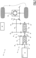
- a vehicle 10 according to an example is shown in the exemplary diagram of Figure 1 .
- the vehicle 10 is for example a heavy-duty vehicle, preferably a truck, a bus or a construction equipment.
- the vehicle 10 comprises two drive wheels 12 and a powertrain 14. In other examples, the vehicle 10 may comprises more than two drive wheels.
- the powertrain 14 is used to drive mechanical components, which in the example are the drive wheels 12.
- the powertrain 14 comprises an electric motor 16, a drivetrain 18 and a differential 20.
- the electric motor 16 comprises a motor shaft 22 on which is mounted a motor gear 24, the motor gear being integral with the motor shaft.
- the electric motor 16 propels the drive wheels 12 through the drivetrain 18 and the differential 20, that is, the electric motor 16 delivers a motor torque to the drivetrain 18, which is then delivered to the differential 20 and the drive wheels 12.
- the vehicle 10 comprises sensors 17, which are configured to measure an angular position ⁇ of the electric motor 16, expressed in ° (degrees), and to measure a motor torque delivered by the electric motor to the drivetrain 18, expressed in N.m (Newton-meter).
- the sensors 17 are integrated into the electric motor 16.
- the sensors 17 measure the angular position ⁇ of the electric motor by measuring the angular position of the motor shaft 22 relative to a housing of the electric motor.
- the drivetrain 18 comprises a transmission, which is, in the example, a four-speed gearbox.
- the gearbox has four gear ratio.
- the gearbox comprises a main shaft 26, on which a first main gear 28, a second main gear 30 and a third main gear 32 are mounted to rotate freely about the main shaft.
- the gearbox also comprises a counter shaft 34, on which are mounted a first counter gear 36, meshing with the motor gear 24, and a second counter gear 38, meshing with the first main gear 28.
- the first and second counter gears are integral, that is, fixed, with the counter shaft.
- the gearbox also comprises an output shaft 40, on which are mounted a first output gear 42, meshing with the second main gear 30, a second output gear 44, meshing with the third main gear 32, and a third output gear 46, meshing with a crown gear of the differential 20.
- the third output gear 46 is also called a pinion gear.
- the first, second and third output gears are integral, that is, fixed, with the output shaft.
- the gearbox also comprises a first dog clutch 48 and a second dog clutch 50.
- the first dog clutch 48 can be engaged with the motor gear 24 or with the first main gear 28, to couple the motor gear 24 or the first main gear 28 with the main shaft 26.
- the second dog clutch 50 can be engaged with the second main gear 30 or with the third main gear 32, to couple the second main gear 30 or the third main gear 32 with the main shaft 26.
- the drivetrain delivers a motor torque produced by the electric motor 16 to the drive wheels 12, and the drivetrain is said to be in a coupled configuration.
- the drivetrain of the example offers four coupled configurations, and the gearbox comprises four speeds, or four gear ratios, depending of the gears with which the dog clutches 48 and 50 are engaged.
- the electric motor 16 is disconnected from the output shaft 40, the differential 20 and the drive wheels 12, and the drivetrain 18 is said to be in an uncoupled configuration.
- the drivetrain has three uncoupled configuration. In a first uncoupled configuration, the first dog clutch 48 and the second clutch 50 are disengaged from the corresponding gears, and the main shaft 26 is not driven by the motor shaft 22.
- the first dog clutch 48 is disengaged from the motor gear 24 and from the first main gear 28 and the second dog clutch 50 is engaged with the second main gear 30 or with the third main gear 32, and the main shaft 26 is not driven by the motor shaft 22, as in the first uncoupled configuration.
- the first dog clutch 48 is engaged with the motor gear 24 or with the first main gear 28 and the second dog clutch 50 is disengaged from the second main gear 30 and from the third main gear 32, and the main shaft 26 is therefore driven by the motor shaft 22 but the output shaft 40 is not driven by the main shaft 26.
- first, second and third main gears 28, 30 and 32 are mounted onto the main shaft 26 through bearing, shown but not referenced in Figure 1 .
- the motor shaft 22, the main shaft 26, the counter shaft 34 and the output shaft 40 are mounted onto a housing of the vehicle 10 through bearings, not shown in Figure 1 , so as to freely rotate relative to the housing with minimal friction.
- Said housing of the vehicle 10 is mounted onto a chassis of the vehicle.
- the electric motor 16 is powered by a rechargeable battery, not shown in the diagram of Figure 1 .
- the electric motor is powered by other means, such as by a fuel cell.
- the vehicle 10 also comprises a control unit 60.
- a method 100 for monitoring the wear of the powertrain 14 of the vehicle 10 is now described, with reference to Figures 2 and 3 .
- the method 100 is performed by the control unit 60.
- All moving mechanical parts of the powertrain 14 have clearance for proper operation. These clearances are determined during the manufacturing of the powertrain, but can increase over time because of wear.
- the method 100 aims to monitor the wear of the powertrain 14 by monitoring an evolution over time of the backlash of the mechanical parts of the powertrain, including the electric motor 16 and the drivetrain 18, said backlash being caused by the clearances between the moving mechanical parts of the powertrain.
- the mechanical parts of the powertrain for which the wear is monitored thanks to the method 100 are internal moveable parts of the electric motor 16, the motor shaft 22, the motor gear 24, the main shaft 26, the first, second and third main gears 28, 30 and 32, the counter shaft 34, the first and second counter gears 36, 38, the output shaft 40, the first, second and third output gears 42, 44 and 46, and the differential 20.
- a backlash value of the two gears is defined as the maximum angular distance through which one of the gears may be moved in one direction without applying a significant force or motion to the other gear in mechanical sequence.
- a backlash value of the powertrain 14 is defined as the maximum angular distance through which the electric motor 16 may be moved in one direction without delivering a significant torque.
- the backlash value of the powertrain 14 corresponds to the angular distance between a first angular position of the electric motor 16 in which the electric motor can deliver a significant torque to the drivetrain 18 by rotating in a first direction of rotation, and a second angular position of the electric motor in which the electric motor can deliver a significant torque to the drivetrain by rotating in a second direction of rotation opposed to the first direction of rotation.
- This angular distance corresponds to the angular distance necessary to compensate for all the clearances in the powertrain.
- an evolution of the backlash value of the powertrain 14 over time is representative of an evolution of the wear of the powertrain.
- the method 100 starts with a reference cycle 110.
- the reference cycle 110 is performed after the vehicle 10 has been manufactured but before it is put into service.
- the reference cycle 110 is performed after the vehicle 10 is put into service and after a running-in, or break-in, period.
- the reference cycle 110 is performed during a recharge of the battery of the vehicle 10.
- the reference cycle 110 is performed after a driver of the electric vehicle 10 requests the electric vehicle to start, and before the vehicle actually starts, or is performed after a driver of the electric vehicle requests the electric vehicle to stop, and before the vehicle actually stops.
- the reference cycle 110 starts with an immobilization step 111, in which the drive wheels 12 of the vehicle 10 are prevented from moving, for example by applying braking to the drive wheels 12 or to non-drive wheels of the vehicle. Furthermore, prior to, or during, the immobilization step 111, the drivetrain 18 is set in a coupled configuration. For example, the first dog clutch 48 is engaged with the motor gear 24 and the second dog clutch 50 is engaged with the second main gear 30.
- the reference cycle 110 then comprises a measuring step 112, during which an initial reference angular position ⁇ 0 ref of the electric motor 16 is measured, preferably with the sensors 17.
- the initial reference angular position ⁇ 0 ref is arbitrarily defined as a zero value, that is, equal to 0°.
- the reference cycle 110 then comprises a rotation step 113, during which the electric motor 16 is rotated in a first direction of rotation until a torque value delivered by the electric motor reaches a predetermined threshold Tmax.
- the torque value delivered by the electric motor is preferably measured with the sensors 17.
- the predetermined threshold value Tmax is preferably comprised between 100 N.m and 600 N.m, for example equal to 300 N.m.
- the electric motor 16 reaches a first reference angular position ⁇ 1 ref .
- the reference cycle 110 then comprises a measuring step 114, during which the angular position of the electric motor 16 is measured, preferably with the sensors 17, to establish a value of the first reference angular position ⁇ 1 ref .
- the first reference angular position ⁇ 1 ref is defined relative to the initial reference angular position ⁇ 0 ref , and is expressed in degree (°), with a positive value.
- the reference cycle 110 then comprises a rotation step 115, during which the electric motor 16 is rotated in a second direction of rotation, opposite to the first direction of rotation, until a torque value delivered by the electric motor reaches the predetermined threshold Tmax.
- the torque value delivered by the electric motor is preferably measured with the sensors 17. It is to be noted that the same predetermined threshold value Tmax is used for both rotation steps 113 and 115 of the reference cycle 110.
- step 115 all the clearances in the powertrain 14 are progressively compensated, until all mechanical parts of the powertrain are in contact with each other and able to transmit a torque in the second direction of movement.
- the reference cycle 110 then comprises a measuring step 116, during which the angular position of the electric motor 16 is measured, preferably with the sensors 17, to establish a value of the second reference angular position ⁇ 2 ref .
- the second reference angular position is defined relative to the initial reference angular position ⁇ 0 ref , and is expressed in degree (°), with a negative value.
- the reference cycle 110 then comprises a calculating step 117, during which a reference backlash value B ref of the powertrain 14 is calculated, on the basis of the first reference angular position ⁇ 1 ref and of the second reference angular position ⁇ 2 ref .
- the reference backlash value B ref is calculated as the difference between the first reference angular position and the second reference angular position, and is expressed in degrees (°).
- the reference cycle 110 then comprises a calculating step 118, during which a first direction reference backlash value B1 ref of the powertrain 14 is calculated, on the basis of the first reference angular position ⁇ 1 ref and of the initial reference angular position ⁇ 0 ref , and a second direction reference backlash value B2 ref of the powertrain 14 is calculated, on the basis of the second reference angular position ⁇ 2 ref and of the initial reference angular position ⁇ 0 ref .
- the first direction reference backlash value is calculated as the difference between the first reference angular position and the initial reference angular position
- the second direction reference backlash value is calculated as the difference between the initial reference angular position and the second reference angular position.
- the reference backlash value B ref is equal to the sum of the first direction reference backlash value B1 ref and of the second direction reference backlash value B2 ref , the reference values B1 ref and B21 ref being positive.
- an initial state of the powertrain 14 is established, represented by the reference backlash values B ref , B1 ref and B2 ref calculated during the steps 117 and 118.
- This initial state is representative of the state of the powertrain 14 after its manufacturing, or after its running-in period, depending on when the reference cycle 110 is performed.
- the method 100 comprises an analysis cycle 120.
- the analysis cycle 120 is performed during the life of the vehicle 10, when it is desired to check the wear of the powertrain 14.
- the analysis cycle 120 is performed during a recharge of the battery of the vehicle 10.
- the analysis cycle 120 is performed after a driver of the electric vehicle 10 requests the electric vehicle to start, and before the vehicle actually starts, or is performed after a driver of the electric vehicle requests the electric vehicle to stop, and before the vehicle actually stops.
- the analysis cycle 120 starts with an immobilization step 121, in which the drive wheels 12 of the vehicle 10 are prevented from moving, for example by applying braking to the drive wheels 12 or to non-drive wheels of the vehicle. Furthermore, prior to, or during, the immobilization step 121, the drivetrain 18 is set in the same coupled configuration as in the reference cycle 110, that is, the same gear ratio of the gearbox is engaged. Hence, in the example, the first dog clutch 48 is engaged with the motor gear 24 and the second dog clutch 50 is engaged with the second main gear 30.
- the analysis cycle 120 then comprises a measuring step 122, during which an initial angular position ⁇ 0 of the electric motor 16 is measured, preferably with the sensors 17.
- the initial angular position ⁇ 0 is arbitrarily defined as a zero value, that is, equal to 0°.
- the analysis cycle 120 then comprises a rotation step 123, during which the electric motor 16 is rotated in the first direction of rotation until a torque value delivered by the electric motor reaches the predetermined threshold Tmax.
- the torque value delivered by the electric motor is preferably measured with the sensors 17. It is to be noted that the same predetermined threshold value Tmax, first direction of rotation and second direction of rotation are used for the reference cycle 110 and for the analysis cycle 120.
- the electric motor 16 reaches a first angular position ⁇ 1.
- the analysis cycle 120 then comprises a measuring step 124, during which the angular position of the electric motor 16 is measured, preferably with the sensors 17, to establish a value of the first angular position ⁇ 1.
- the first angular position ⁇ 1 is defined relative to the initial angular position ⁇ 0, and is expressed in degree (°), with a positive value.
- the analysis cycle 120 then comprises a rotation step 125, during which the electric motor 16 is rotated in the second direction of rotation, until a torque value delivered by the electric motor reaches the predetermined threshold Tmax.
- the torque value delivered by the electric motor is preferably measured with the sensors 17.
- step 125 all the clearances in the powertrain 14 are progressively compensated, until all mechanical parts of the powertrain are in contact with each other and able to transmit a torque in the second direction of movement.
- the analysis cycle 120 then comprises a measuring step 126, during which the angular position of the electric motor 16 is measured, preferably with the sensors 17, to establish a value of the second angular position ⁇ 2.
- the second angular position is defined relative to the initial angular position, and is expressed in degree (°), with a negative value.
- the analysis cycle 120 then comprises a calculating step 127, during which a backlash value B of the powertrain 14 is calculated, on the basis of the first angular position ⁇ 1 and of the second angular position ⁇ 2.
- the backlash value B is calculated as the difference between the first angular position ⁇ 1 and the second angular position ⁇ 2, and is expressed in degrees (°).
- the analysis cycle 120 then comprises a calculating step 128, during which a first direction backlash value B1 of the powertrain 14 is calculated, on the basis of the first angular position ⁇ 1 and of the initial angular position ⁇ 0, and a second direction backlash value B2 of the powertrain 14 is calculated, on the basis of the second angular position ⁇ 2 and of the initial angular position ⁇ 0.
- the first direction backlash value B1 is calculated as the difference between the first angular position ⁇ 1 and the initial angular position ⁇ 0
- the second direction backlash value B2 is calculated as the difference between the initial angular position ⁇ 0 and the second angular position ⁇ 2.
- the backlash value B is equal to the sum of the first direction backlash value B1 and of the second direction backlash value B2, the reference values B1 ref and B21 ref being positive.
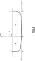
- FIG. 3 the movements of the electric motor 16 during the analysis cycle 120 are represented.
- the graph in Figure 3 shows the angular position ⁇ of the electric motor 16 on the horizontal axis, and the motor torque T delivered by the electric motor on the vertical axis.
- the electric motor 16 is in a steady state condition and delivers no motor torque, and the angular position ⁇ corresponds to the initial angular position ⁇ 0.
- the angular position ⁇ increases progressively.
- the motor torque T increases at the same time. Then, when all the clearances in the powertrain are compensated, the motor torque T increases rapidly and reaches an asymptote. Furthermore, when the motor torque T reaches the predetermined threshold Tmax, the electric motor 16 is in the first angular position ⁇ 1.
- the angular position ⁇ decreases progressively and the motor torque T becomes equal to zero until the angular position ⁇ reaches the initial angular position ⁇ 0. Then, the angular position ⁇ continues to decrease, and as the clearance of the mechanical parts of the powertrain 14 is progressively compensated by the rotation of the electric motor, the motor torque T increases at the same time. Then, when all the clearances in the powertrain are compensated, the motor torque T increases rapidly and reaches an asymptote. Furthermore, when the motor torque T reaches the predetermined threshold Tmax, the electric motor 16 is in the second angular position ⁇ 2.
- Figure 3 shows that the backlash value B is equal to the difference between the first angular position ⁇ 1 and the second angular position ⁇ 2, expressed in degrees.
- the rotation of the electric motor 16 during the rotation steps 113, 115, of the reference cycle 110, and during the rotation steps 123 and 125 of the analysis cycle 120 is comprised between 10 rpm and 50 rpm.
- This relatively slow rotational speed allows to progressively bring together all mechanical parts within the powertrain 14 while allowing for a precise measurement of the angular position of the electric motor.
- the method 100 comprises a comparison step 130, in which the backlash value B obtained during the analysis cycle 120 is compared to the reference backlash value B ref obtained during the reference cycle 110, and in which, preferably, the first direction backlash value B1 and the second direction backlash value B2 obtained during the analysis cycle 120 are respectively compared to the first direction reference backlash value B1 ref and the second direction reference backlash value B2 ref obtained during the reference cycle 110, to monitor the evolution of the wear of the powertrain.
- the comparison of the backlash values B, B1 and B2 obtained at the end of the analysis cycle 120, with the reference backlash values B ref , B1 ref and B2 ref obtained at the end of the reference cycle 110, allows to detect an evolution in the wear of the powertrain 14, which corresponds to an evolution in the clearances between the mechanical parts of the electric motor 16 and of the drivetrain 18.
- the evolution of said clearances is representative of a degradation, or wear, of the parts of the powertrain 14.
- B1, B1ref, B2 and B2ref could not be compared because the "zero" ( ⁇ 0) is never the same. Consequently, only B and B ref could be compared.
- the evolution of the backlash values can show an increase of wear of the powertrain, or a stagnation of the wear of the powertrain, the latter being a sign of good health of the powertrain.
- an increase in the backlash values corresponding to an increase in the clearance between said parts, can be sign of:
- the method 100 ends with an alert step 140, during which an alert is emitted to the attention of a driver or a controller of the vehicle 10, informing of the existence of a defect in the powertrain 14 and alerting that maintenance should be performed on the powertrain.
- the method 100 continues.
- the method 100 repeats an analysis cycle 120, an then a comparison step 130, as described above.
- the waiting period is, for example, defined as a number of days, or weeks, before the analysis cycle 120 is repeated. Alternatively, the waiting period is defined as a distance to be travelled by the vehicle 10 before the analysis cycle 120 is repeated.
- the method 100 continues to monitor the evolution over time of the wear of the powertrain 14 during the use of the vehicle 10, by monitoring the evolution of the backlash values B, B1 and B2, until a defect or significant wear is detected.
- the method 100 described above is particularly advantageous, as it allows detecting wear and defect within the powertrain 14, including the electric motor 16, easily. Indeed, the method can be implemented on conventional electric vehicles, without requiring structural modification of such vehicles. Its implementation is therefore simple and inexpensive.
- electric motors are generally equipped with the torque and angular position sensors such as those used in the example described above.
- the method 100 allows for detecting a large variety of defects, as any defect increasing clearances between mechanical parts of the powertrain 14 is influencing the backlash value B measured by the method.
- the monitoring of the first direction backlash value B1 and of the second direction backlash value B2 allows for a more precise monitoring of the wear within the powertrain 14. As some defects are only affecting the backlash of the powertrain in one direction of rotation of the electric motor, detecting an increase in only one of the backlash values B1 or B2 allows for identifying the location and/or the type of wear within the powertrain.
- the method 100 is without constraint to a driver of the vehicle 10, as it does not alter driving of the vehicle and does not require any driver intervention.
- the method 100 is performed with only one gear ratio of the gearbox.
- the method 100 is performed for each gear ratio of the gearbox.
- the method 100 is performed four times. Performing the method 100 for each gear ratio of the gearbox is particularly advantageous, as it allows locating wear within the powertrain 14.
- an increase in the backlash value B is more important when the method 100 is performed for a given gear ratio, then it can be concluded that the wear is located at least in mechanical parts of the powertrain 14 which are only driven by the electric motor 16 when the gearbox is set at said gear ratio. For example, if an increase in the backlash value B is only observed when the first dog clutch 48 is engaged with the first main gear 28, then it can be concluded that the wear is located on the first main gear 28 or on the bearings with which the first main gear 28 is mounted onto the main shaft 26 or into the countershaft 34.
- the vehicle 10 described above is of standard conception. Thus, various modifications can be envisaged without affecting the execution of method 100.
- the gearbox can have a number of speed different from four, for example two or eight; and/or a number of dug clutches different from two, for example one or three.
- the powertrain 14 does not comprise a differential.
- the drivetrain 18 does not comprise a gearbox, but another type of transmission, such as a fixed transmission or a continuously variable transmission.
- the powertrain 14 comprises multiple electric motors, for example two or three electric motors.
- the drivetrain 18 comprises two inputs, each electric motor being one input of the drivetrain, and one output, connected to the differential 20.
- the method 100 is performed multiple times, preferably once for each electric motor of the vehicle.
- the motor torque delivered by the electric motor 16 to the drivetrain 18 is delivered by the drivetrain to the drive wheels 12 of the vehicle, said drive wheels being mechanical components of the vehicle.
- the motor torque is delivered by the drivetrain 18 to other mechanical components of the vehicle 10, such as, for example, a compressor, a pump, and/or any other mechanical component requiring an input torque to be driven.
- the powertrain 14 is configured to drives mechanical components in rotation.
- the method 100 is performed as described above, with the drivetrain in a coupled configuration and with the mechanical components prevented from moving during the reference cycle 110 and during the analysis cycle 120.
- the drivetrain 18 can deliver the motor torque of electric motor 16 simultaneously to the drive wheels 12 and to other mechanical components of the vehicle 10.
- the method 100 does not comprises the reference cycle 110.
- the analysis cycle 120 is repeated and the backlash values B, B1 and B2 established during the steps 127 and 128 of the last performed analysis cycle 120 are compared with backlash values B, B1 and B2 established during previously performed analysis cycles 120, to detect an evolution over time of the wear of the powertrain 14.
- the backlash values B, B1 and B2 obtained during an analysis cycle 120 are compared to reference values obtained by other means, such as through calculation or with reference vehicles, instead or in addition of being compared to the backlash values B ref , B1 ref and B2 ref obtained during the reference cycle 110 and to the backlash values B, B1 and B2 obtained during the previously executed analysis cycles 120.
- the initial reference angular position ⁇ 0 ref and the initial angular position ⁇ 0 are not measured during the reference cycle 110 and the analysis cycle 120, and therefore, the first and second direction reference backlash values B1 ref , B2 ref and the first and second direction backlash values B1, B2 are not calculated.
- Example 1 a method 100 for monitoring the wear of a powertrain 14 of an electric vehicle 10, the powertrain 14 comprising at least one electric motor 16 and a drivetrain 18, the drivetrain being configured to deliver a motor torque produced by the electric motor 16 to mechanical components 12 of the electric vehicle 10 to drive the mechanical components, wherein the method 100 comprises an analysis cycle 120 that includes, in this order:
- Example 2 the method 100 of example 1, wherein the analysis cycle 120 further includes:
- Example 3 the method 100 of either one of examples 1 and 2, wherein, prior to the rotation 123 of the electric motor 16 in the first direction of rotation during the analysis cycle 120, the electric motor is in an initial angular position ⁇ 0, wherein the analysis cycle 120 further includes:
- Example 4 the method 100 of examples 2 and 3 considered in combination, wherein the analysis cycle 120 further includes:
- Example 5 the method 100 of any one of examples 1 to 4, wherein the method 100 further comprises a reference cycle 110, performed before the analysis cycle 120, wherein the reference cycle 110 includes, in this order:
- Example 6 the method 100 of example 5, wherein the reference cycle 110 further includes:
- Example 7 the method 100 of either one of examples 5 and 6, wherein, prior to the rotation 113 of the electric motor 16 in the first direction of rotation during the reference cycle 110, the electric motor is in an initial reference angular position ⁇ 0 ref , wherein the reference cycle 110 further includes:
- Example 8 the method 100 of examples 6 and 7 considered in combination, wherein the initial cycle 110 further includes:
- Example 9 The method 100 of any one of examples 1 to 8, wherein the analysis cycle 120 is performed:
- Example 10 the method 100 of any one of examples 1 to 8, wherein the electric vehicle 10 is a rechargeable battery electric vehicle, the electric motor 16 being powered by a battery, and wherein the analysis cycle 120 is performed during a recharge of the battery.
- Example 11 the method 100 of any one of examples 1 to 10, wherein the method 100 further comprises repeating the analysis cycle 120 over time to monitor an evolution over time of the backlash values B calculated 127 during the repeated analysis cycles 120.
- Example 12 the method 100 of any one of examples 1 to 11, wherein the drivetrain 18 comprises a gearbox having multiple gear ratio, and wherein the method 100 is performed for each gear ratio of the gearbox, to calculate a backlash value of the powertrain 14 for each gear ratio of the gearbox.
- Example 13 the method 100 of any one of examples 1 to 12, wherein the mechanical components 12 of the vehicle 10 include drive wheels 12 of the vehicle, and wherein, during the analysis cycle 120 of the method, braking is applied on the vehicle to prevent 121 the movement of the vehicle and of the drive wheels.
- Example 14 a vehicle 10, comprising:
- Relative terms such as “below” or “above” or “upper” or “lower” or “horizontal” or “vertical” may be used herein to describe a relationship of one element to another element as illustrated in the Figures. It will be understood that these terms and those discussed above are intended to encompass different orientations of the device in addition to the orientation depicted in the Figures. It will be understood that when an element is referred to as being “connected” or “coupled” to another element, it can be directly connected or coupled to the other element, or intervening elements may be present. In contrast, when an element is referred to as being “directly connected” or “directly coupled” to another element, there are no intervening elements present.
Landscapes
- Engineering & Computer Science (AREA)
- Mechanical Engineering (AREA)
- Physics & Mathematics (AREA)
- General Physics & Mathematics (AREA)
- Transportation (AREA)
- General Engineering & Computer Science (AREA)
- Automation & Control Theory (AREA)
- Power Engineering (AREA)
- Combustion & Propulsion (AREA)
- Chemical & Material Sciences (AREA)
- Human Computer Interaction (AREA)
- Life Sciences & Earth Sciences (AREA)
- Sustainable Development (AREA)
- Sustainable Energy (AREA)
- Electric Propulsion And Braking For Vehicles (AREA)
Priority Applications (3)
| Application Number | Priority Date | Filing Date | Title |
|---|---|---|---|
| EP23180441.0A EP4481236A1 (fr) | 2023-06-20 | 2023-06-20 | Procédé de surveillance de l'usure d'un groupe motopropulseur d'un véhicule électrique et véhicule électrique mettant en oeuvre un tel procédé |
| US18/664,954 US20240424908A1 (en) | 2023-06-20 | 2024-05-15 | Method for monitoring the wear of a powertrain of an electric vehicle and electric vehicle implementing said method |
| CN202410774357.9A CN119164526A (zh) | 2023-06-20 | 2024-06-17 | 用于监测电动车辆的动力传动系统的磨损的方法及实施所述方法的电动车辆 |
Applications Claiming Priority (1)
| Application Number | Priority Date | Filing Date | Title |
|---|---|---|---|
| EP23180441.0A EP4481236A1 (fr) | 2023-06-20 | 2023-06-20 | Procédé de surveillance de l'usure d'un groupe motopropulseur d'un véhicule électrique et véhicule électrique mettant en oeuvre un tel procédé |
Publications (1)
| Publication Number | Publication Date |
|---|---|
| EP4481236A1 true EP4481236A1 (fr) | 2024-12-25 |
Family
ID=86904164
Family Applications (1)
| Application Number | Title | Priority Date | Filing Date |
|---|---|---|---|
| EP23180441.0A Pending EP4481236A1 (fr) | 2023-06-20 | 2023-06-20 | Procédé de surveillance de l'usure d'un groupe motopropulseur d'un véhicule électrique et véhicule électrique mettant en oeuvre un tel procédé |
Country Status (3)
| Country | Link |
|---|---|
| US (1) | US20240424908A1 (fr) |
| EP (1) | EP4481236A1 (fr) |
| CN (1) | CN119164526A (fr) |
Families Citing this family (1)
| Publication number | Priority date | Publication date | Assignee | Title |
|---|---|---|---|---|
| JP2025018301A (ja) * | 2023-07-26 | 2025-02-06 | 本田技研工業株式会社 | 検査装置、検査方法及び車両 |
Citations (3)
| Publication number | Priority date | Publication date | Assignee | Title |
|---|---|---|---|---|
| US20100235027A1 (en) * | 2009-03-16 | 2010-09-16 | Hyundai Motor Company | Method for reducing vibration caused by gear backlash in drive system for hybrid vehicle |
| DE102018215894A1 (de) * | 2018-09-19 | 2020-03-19 | Robert Bosch Gmbh | Verfahren zur Ermittlung des Getriebespieles eines Getriebes |
| EP3734117A1 (fr) * | 2019-04-11 | 2020-11-04 | Camozzi Automation S.p.A. | Méthode pour détecter l'état d'usure d'un actionneur électrique |
Family Cites Families (1)
| Publication number | Priority date | Publication date | Assignee | Title |
|---|---|---|---|---|
| DE102021125114B3 (de) * | 2021-09-28 | 2022-09-22 | Schaeffler Technologies AG & Co. KG | Elektrischer Achsantriebsstrang, Steuereinheit und Computerprogrammprodukt |
-
2023
- 2023-06-20 EP EP23180441.0A patent/EP4481236A1/fr active Pending
-
2024
- 2024-05-15 US US18/664,954 patent/US20240424908A1/en active Pending
- 2024-06-17 CN CN202410774357.9A patent/CN119164526A/zh active Pending
Patent Citations (3)
| Publication number | Priority date | Publication date | Assignee | Title |
|---|---|---|---|---|
| US20100235027A1 (en) * | 2009-03-16 | 2010-09-16 | Hyundai Motor Company | Method for reducing vibration caused by gear backlash in drive system for hybrid vehicle |
| DE102018215894A1 (de) * | 2018-09-19 | 2020-03-19 | Robert Bosch Gmbh | Verfahren zur Ermittlung des Getriebespieles eines Getriebes |
| EP3734117A1 (fr) * | 2019-04-11 | 2020-11-04 | Camozzi Automation S.p.A. | Méthode pour détecter l'état d'usure d'un actionneur électrique |
Also Published As
| Publication number | Publication date |
|---|---|
| US20240424908A1 (en) | 2024-12-26 |
| CN119164526A (zh) | 2024-12-20 |
Similar Documents
| Publication | Publication Date | Title |
|---|---|---|
| KR101704279B1 (ko) | Dct의 클러치 고장진단방법 | |
| US11796047B2 (en) | Method for determining the transmission backlash of a transmission | |
| US20240424908A1 (en) | Method for monitoring the wear of a powertrain of an electric vehicle and electric vehicle implementing said method | |
| US20120109474A1 (en) | Driveline lash management in powertrain systems | |
| CN101497308B (zh) | 蛇形皮带有效寿命监视器 | |
| US6526816B2 (en) | Transmission gear life monitor system | |
| CN101022975A (zh) | 自动机动车辆动力传动系统及其控制方法 | |
| EP3312068A1 (fr) | Protection contre les dommages pour essieu multi-fonction | |
| EP4468592A1 (fr) | Procédé de surveillance de l'état de santé d'un groupe motopropulseur d'un véhicule électrique et véhicule électrique mettant en oeuvre ledit procédé | |
| CN110715803A (zh) | 一种蜗轮蜗杆减速箱性能试验装置和方法 | |
| CN105683013B (zh) | 使用发动机的旋转速度估计防止所述发动机熄火的方法 | |
| EP3936737B1 (fr) | Procédé de fonctionnement d'un groupe motopropulseur de véhicule | |
| US12017635B2 (en) | Slip detection and mitigation for an electric drive powertrain having a high ratio traction drive transmission | |
| JP2020502441A (ja) | ボールランプアセンブリにおけるボール損失を判定および予測する方法 | |
| US20230063948A1 (en) | Method of disengaging a clutching device and electric driveline | |
| CN119137025A (zh) | 用于基于车轮扭矩的车辆操作的方法和传感器装置 | |
| CN101135348A (zh) | 用于估算离合器滑移量的装置 | |
| CN111890922B (zh) | 一种汽车加速跑偏控制装置 | |
| JP2020067391A (ja) | 異常診断装置 | |
| CN111891115B (zh) | 一种汽车加速跑偏控制方法 | |
| JP3085166B2 (ja) | パワートレーンの性能試験装置 | |
| JPH09325089A (ja) | パワートレーンの性能試験装置 | |
| US20260001396A1 (en) | Method for controlling a powertrain of an electric vehicle and associated electric vehicle | |
| CN114754121A (zh) | 用于差速器系统的控制和诊断方法 | |
| US20250163878A1 (en) | Predictive engine stop-start based on clutch energy |
Legal Events
| Date | Code | Title | Description |
|---|---|---|---|
| PUAI | Public reference made under article 153(3) epc to a published international application that has entered the european phase |
Free format text: ORIGINAL CODE: 0009012 |
|
| STAA | Information on the status of an ep patent application or granted ep patent |
Free format text: STATUS: THE APPLICATION HAS BEEN PUBLISHED |
|
| AK | Designated contracting states |
Kind code of ref document: A1 Designated state(s): AL AT BE BG CH CY CZ DE DK EE ES FI FR GB GR HR HU IE IS IT LI LT LU LV MC ME MK MT NL NO PL PT RO RS SE SI SK SM TR |
|
| STAA | Information on the status of an ep patent application or granted ep patent |
Free format text: STATUS: REQUEST FOR EXAMINATION WAS MADE |
|
| 17P | Request for examination filed |
Effective date: 20241223 |