EP4481260A1 - Dispositif de surveillance et procédé de fonctionnement d'un dispositif de surveillance - Google Patents
Dispositif de surveillance et procédé de fonctionnement d'un dispositif de surveillance Download PDFInfo
- Publication number
- EP4481260A1 EP4481260A1 EP23181051.6A EP23181051A EP4481260A1 EP 4481260 A1 EP4481260 A1 EP 4481260A1 EP 23181051 A EP23181051 A EP 23181051A EP 4481260 A1 EP4481260 A1 EP 4481260A1
- Authority
- EP
- European Patent Office
- Prior art keywords
- monitoring device
- sensor
- protective field
- safety
- distance sensors
- Prior art date
- Legal status (The legal status is an assumption and is not a legal conclusion. Google has not performed a legal analysis and makes no representation as to the accuracy of the status listed.)
- Pending
Links
Images
Classifications
-
- F—MECHANICAL ENGINEERING; LIGHTING; HEATING; WEAPONS; BLASTING
- F16—ENGINEERING ELEMENTS AND UNITS; GENERAL MEASURES FOR PRODUCING AND MAINTAINING EFFECTIVE FUNCTIONING OF MACHINES OR INSTALLATIONS; THERMAL INSULATION IN GENERAL
- F16P—SAFETY DEVICES IN GENERAL; SAFETY DEVICES FOR PRESSES
- F16P3/00—Safety devices acting in conjunction with the control or operation of a machine; Control arrangements requiring the simultaneous use of two or more parts of the body
- F16P3/12—Safety devices acting in conjunction with the control or operation of a machine; Control arrangements requiring the simultaneous use of two or more parts of the body with means, e.g. feelers, which in case of the presence of a body part of a person in or near the danger zone influence the control or operation of the machine
- F16P3/14—Safety devices acting in conjunction with the control or operation of a machine; Control arrangements requiring the simultaneous use of two or more parts of the body with means, e.g. feelers, which in case of the presence of a body part of a person in or near the danger zone influence the control or operation of the machine the means being photocells or other devices sensitive without mechanical contact
- F16P3/144—Safety devices acting in conjunction with the control or operation of a machine; Control arrangements requiring the simultaneous use of two or more parts of the body with means, e.g. feelers, which in case of the presence of a body part of a person in or near the danger zone influence the control or operation of the machine the means being photocells or other devices sensitive without mechanical contact using light grids
Definitions
- the invention relates to a monitoring device and a method for operating a monitoring device.
- Such monitoring devices are used in particular for monitoring danger areas on hazardous systems.
- a danger area on such a system is monitored with an optical sensor, which is generally designed as a scanning sensor in such a way that a monitoring area, in particular the danger area, is periodically scanned with the light beams of a transmitting/receiving unit of this optical sensor.
- the optical sensor can be designed as an area distance sensor, i.e. a scanning distance sensor, with which the positions of objects in the monitoring area can be determined.
- a scanning optical sensor is used in such a way that object monitoring is not carried out in the entire monitoring area, i.e. the danger area, but only within a specified protective field.
- the protective field is stored as a parameter in the optical sensor, with its dimension being adapted as best as possible to the danger area to be monitored.
- the evaluation of the measurement data generated by the optical sensor takes place in the optical sensor.
- an evaluation unit is integrated in the optical sensor, which evaluates the received signals at the output of a receiver of the transmitting/receiving unit.
- a binary An object detection signal is generated whose switching states indicate whether there is an object within the protective field.
- This object detection signal is sent to a controller that controls the system. If an object detection signal is sent that indicates that there is no object in the protective field, the system is allowed to operate. If the optical sensor generates an object detection signal with the switching state that corresponds to an object detection in the protective field, this object detection signal shuts down the system via the controller in order to avoid dangerous situations.
- the optical sensor in particular the area distance sensor of the monitoring device, has a fail-safe structure in order to meet the normative safety requirements.
- the evaluation unit in particular has a multi-channel structure, for example in the form of two cyclically monitoring computer units.
- Such unnecessary downtimes can in principle be avoided by specifying longer integration times for the generation of the switching signal, ie the optical sensor transmits a message via a large number of measured values in order to average out short-term disturbances so that they no longer influence the generation of the switching signal.
- the invention is based on the object of realizing a high level of security for a monitoring device of the type mentioned above, while at the same time ensuring high availability.
- the invention relates to a method for operating a monitoring device with sensor means, by means of which protective field monitoring is carried out.
- a safety function is triggered depending on sensor signals from the sensor means.
- Two surface distance sensors are present as sensor means, by means of which the same protective field is monitored.
- the safety function is only triggered if an object intrusion in the protective field is registered simultaneously by both surface distance sensors.
- the invention further relates to a method for operating a monitoring device.
- a safety-relevant monitoring function is realized in that a protective field is monitored simultaneously with two area distance sensors, whereby a safety function is generated as a safety-relevant result of the protective field monitoring depending on the sensor signals of the area distance sensors.
- the safety function is only generated when both area distance sensors register an object intrusion in the protective field at the same time. This ensures a high level of availability of the monitoring device, since a malfunction of an area distance sensor does not trigger the safety function, as this safety function is only generated when both area distance sensors in the protective field register an object intrusion.
- the redundant sensor arrangement with two area distance sensors avoids unnecessary generation of a safety function while ensuring a safe monitoring function. This is particularly true when the area distance sensors report an object intrusion due to interfering particles, such as small flying parts, chips or the like. Since the area distance sensors do not scan the protective field synchronously, it is very unlikely that both area distance sensors will detect such interfering particles at the same time. In general, each area distance sensor emits beams that are periodically guided within a detection area. Since the two area distance sensors are not synchronized with regard to these scanning movements, the probability is very low that the scanning beams of the area distance sensors will detect these interfering particles at the same time. Therefore, only one area distance sensor ever detects such interfering particles, but not both area distance sensors at the same time, so that these interfering particles do not trigger the safety function.
- the monitoring device can thus filter out interference effects without increasing the integration times during object detection in such a way that, in the presence of Due to such interference effects, both surface distance sensors do not report an object intrusion at the same time. This ensures a high level of availability of the monitoring device according to the invention without increasing the integration times.
- a binary switching signal is generated as an output signal in each area distance sensor, whereby the binary switching signal assumes the switching state ON when there is no object in the protective field.
- the binary switching signal assumes the switching state OFF when there is an object in the protective field.
- the switching signals are linked in an evaluation circuit with an OR link.
- the evaluation circuit triggers the safety function when both switching signals are in the OFF switching state.
- each area distance sensor has a safety switching output via which the respective switching signal is output to the evaluation circuit.
- the OR link allows the switching signals of the area distance sensors to be logically linked in a simple manner.
- the evaluation circuit ensures that the safety function is only triggered if both area distance sensors simultaneously report an object intrusion in the protective field.
- the evaluation circuit can be integrated in one of the area distance sensors, whereby the evaluation circuit is then connected to the other area distance sensor via a data connection.
- the evaluation circuit forms a separate unit outside the area distance sensors and is connected to them via data connections.
- the area distance sensors are designed as safety sensors that have a have a fail-safe design.
- the evaluation circuit also advantageously has a fail-safe design.
- the fail-safe design of the area distance sensors designed as safety sensors is advantageously implemented by a redundant evaluation unit for evaluating sensor signals from the area distance sensor.
- the evaluation unit can be formed by two computer units that monitor each other cyclically.
- the safety switching outputs of the area distance sensors can also be designed to be fail-safe, for example by a two-channel design or by error control using test signals that are output by the evaluation unit to the respective safety switching output and read back into the evaluation unit. The read-back test signals are then compared with specified target values for error control.
- safe bus connections can also be provided for the formation of output structures.
- a danger zone on a system is monitored using the surface distance sensors.
- the evaluation circuit is then formed by a safety controller that controls the system.
- the safety controller can also have a redundant, multi-channel computer unit, which makes it fail-safe.
- the safety function shuts down the system and triggers a restart lock.
- the restart interlock prevents an uncontrolled restart of the system, which could pose a risk to people in the vicinity of the system.
- an automatic restart takes place if, when the safety function is triggered, no object intervention in the protective field is registered for a predetermined time interval with at least one area distance sensor.
- An automatic restart is advantageously initiated by registering in the evaluation circuit that the condition for triggering the safety function is no longer fulfilled.
- the evaluation circuit in particular the safety control, not only triggers the safety function when the area distance sensors simultaneously detect an object in the protective field. Rather, the evaluation circuit also controls the automatic restart depending on the switching signals of the area distance sensor that are output via the safety switching outputs.
- the evaluation circuit requires that the area distance sensors generate switching signals over a specified period of time that would not trigger a safety function. This monitoring ensures that there is no dangerous state in the protective field over the entire period of time, so that the evaluation circuit can then cancel the restart lock and enable the automatic restart of the system.
- the monitoring device has a high level of availability, since it is sufficient for an automatic restart if only one surface distance sensor generates a switching signal with the switching state ON. ie reports a free protective field.
- the other area distance sensor can generate a switching signal with the switching state OFF, particularly as a result of a fault or as a result of the detection of a disturbing object.
- every area distance sensor can be designed as a radar sensor or an ultrasonic sensor.
- every area distance sensor is an optical sensor.
- the functionality of the sensor means is advantageously such that a flat detection area is scanned with each area distance sensor within successive scans.
- the switching signal is generated at the end of each scan depending on the sensor signals received in this scan.
- the evaluation of whether an object is present in the protective field or not is therefore always carried out after a scan, whereby the sensor signals for this scan are then evaluated in the evaluation unit in order to generate the respective switching signal.
- the preferably identical area distance sensors generate their switching signal at the end of each scan.
- the scans of the two area distance sensors inevitably overlap in time. If an object intrusion in the protective field is detected by both area distance sensors in the overlapping time interval of two scans of the area distance sensor, the safety function is triggered.
- each area distance sensor emits light beams in the form of light pulses, wherein distance measurements are carried out by means of a light transit time method.
- the pulse spacing of the light beams is significantly larger than the measured light travel times when detecting objects in the protective field.
- a mutual influence of the area distance sensors is very unlikely because the light beams of the area distance sensors are most likely emitted in different directions, so that the probability that the light beams of both area distance sensors hit an object in the protective field at the same time and thus the light beams of one area distance sensor are guided to the other area distance sensor and cause a false detection there is extremely low.
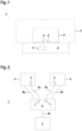
- FIG. 1 shows schematically an embodiment of the monitoring device 1 according to the invention.
- the monitoring device 1 serves to monitor a danger area 2 on a system 3.
- Two area distance sensors 4 are used as components of the monitoring device 1.
- the area distance sensors 4 are identical and are mounted at a distance from one another, for example at opposite corners on the system 3, so that the area in front of the system 3 is monitored by the area distance sensors 4.
- the system 3 is controlled by a safety controller 5 which has a fail-safe structure.
- the fail-safe structure is preferably implemented by two computer units which cyclically monitor each other.
- the area distance sensors 4 are used to monitor the protective field. According to the invention, the area distance sensors 4 monitor the same protective field 6 that covers part of the danger zone 2. In general, several protective fields 6 can also be stored in the area distance sensors 4, so that different protective fields 6 can be activated depending on the current application conditions, although the same protective field 6 is always monitored with the area distance sensors 4. The selection of the protective fields 6 can be carried out by configuration using the safety controller 5.
- FIG. 2 shows a block diagram of the monitoring device 1 according to the invention.
- the system 3 has two safety switching inputs 7.
- Each area distance sensor 4 has a fail-safe safety switching output 8, via which switching signals from the area distance sensors 4 are read in.
- the switching signals are read in via a first data line 9a, whereby these data lines 9a are led to the safety switching inputs 7 of the system 3.
- the area distance sensors 4 are connected to the safety controller 5 via further data lines 9b. These data lines 9b provide a fail-safe data connection, via which a bidirectional data exchange can take place between the safety controller 5 and the area distance sensors 4. This allows the area distance sensors 4 to be connected to the Safety control 5 can be configured, ie parameterized. In particular, the protective field 6 for the two area distance sensors 4 can be specified via the safety control 5. Finally, the safety control 5 is connected to the system 3 via a further data line 9c. Control signals are sent from the safety control 5 to the system 3 via this data line 9c.
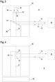
- Figure 3 shows a first embodiment of the area distance sensor 4 in the form of an optical sensor.
- the area distance sensor 4 has a transmitting/receiving unit 10 with a transmitter 12 emitting light beams 11 and a receiver 13 receiving light beams 11.
- the transmitter 12 is formed, for example, by a laser diode
- the receiver 13 is formed, for example, by a photodiode.
- a receiving optics 14 is assigned to the receiver 13.
- the transmitting/receiving unit 10 is integrated in a stationary manner in a housing 15.
- a deflection unit 16 which has a motor-driven deflection mirror 17 which can be rotated about a rotation axis D.
- the light beams 11 emitted by the transmitter 12 and the light beams 11 reflected back by an object O to be detected are guided via the deflection mirror 17.
- the rotational movement of the deflection mirror 17 periodically guides the light beams 11 in the monitoring area.
- the current rotational position of the deflection mirror 17 and thus the current beam direction of the light beams 11 are recorded by means of an angle sensor.
- the transmitting/receiving unit 10 forms a distance sensor that operates according to a pulse-time-of-flight method.
- the transmitter 12 therefore emits sequences of light pulses.
- the light time of a light pulse from the transmitter 12 to an object O and back to the receiver 13 is determined.
- distance measurements can be carried out using a phase measurement method.
- Figure 4 shows a second embodiment of the area distance sensor 4.
- a transmitting/receiving unit 10 with a transmitter 12 emitting light beams 11 and a receiver 13 receiving light beams 11 is arranged in a rotating measuring head 18.
- the optical sensor according to Figure 4 the embodiment according to Figure 3 .
- the safety sensor 4 in the form of the area distance sensor 4 detects a two-dimensional detection area.
- the detection area is periodically scanned in individual scans with the light beams 11. Accordingly, the safety sensor 4 monitors the protective field in two-dimensional protective fields 6.
- Each area distance sensor 4 of the monitoring device 1 forms a safety sensor.
- the area distance sensor 4 designed as a safety sensor generally has an evaluation unit in which received signals from the receiver 13 are evaluated.
- protective field monitoring generally takes place in such a way that the evaluation unit checks whether an object O is present in the protective field 6 or not.
- the evaluation unit generates a binary switching signal as an object detection signal, the switching states of which indicate whether an object O is in the protective field 6 or not. If no object O is registered in the protective field 6, the switching signal assumes the switching state ON. If an object O is registered in the protective field 6, the switching signal assumes the switching state OFF. The switching signal is regenerated at the end of each scan.
- the evaluation unit has a fail-safe design. This is achieved, for example, by Evaluation unit consists of two mutually monitoring computer units.
- a safety function is only triggered in the monitoring device 1 if an object 0 in the protective field 6 is detected in both area distance sensors 4 at the same time.
- the switching signals of the area distance sensors 4 are generally fed to an evaluation circuit, in this case the safety controller 5. There, an OR link of the switching signals takes place so that the safety function is only generated when the switching signals of both area distance sensors 4 simultaneously assume the OFF switching state.
- the safety function consists in the fact that system 3 is shut down and a restart lock is triggered, which prevents an uncontrolled restart of system 3.
- These functions are carried out by the safety control 5, which controls system 3 depending on the switching signals of the area distance sensors 4.
- the safety controller 5 can also be used to automatically restart system 3. This automatic restart occurs automatically in the safety controller 5 when it determines that the condition for triggering the safety function is no longer met for a specified period of time.
- the safety controller 5 continuously evaluates the switching signals read from the area distance sensors 4. If the safety controller 5 registers that at least the switching signal of an area distance sensor 4 remains permanently in the ON state for the specified period of time, the safety controller 5 triggers the automatic restart of the system 3 and the restart lock is removed.
- the area distance sensors 4 are also insensitive to mutual influences and the resulting misdetections. Since the scanning movements of the light beams 11 of the two area distance sensors 4 are not synchronized, the directions of the light beams 11 are always or almost always different, so that it is very unlikely that light beams 11 of an area distance sensor 4 will strike an object O and from there be guided to the other area distance sensor 4 in such a way that these light beams 11 are superimposed on a distance measurement of the other area distance sensor 4.
- the insensitivity to mutual influences of the two area distance sensors 4 can be further increased by making the pulse intervals of the light beams 11 significantly greater than the measured light travel times when detecting objects O in the protective field 6.
Landscapes
- Engineering & Computer Science (AREA)
- General Engineering & Computer Science (AREA)
- Mechanical Engineering (AREA)
- Optical Radar Systems And Details Thereof (AREA)
Priority Applications (1)
| Application Number | Priority Date | Filing Date | Title |
|---|---|---|---|
| EP23181051.6A EP4481260A1 (fr) | 2023-06-22 | 2023-06-22 | Dispositif de surveillance et procédé de fonctionnement d'un dispositif de surveillance |
Applications Claiming Priority (1)
| Application Number | Priority Date | Filing Date | Title |
|---|---|---|---|
| EP23181051.6A EP4481260A1 (fr) | 2023-06-22 | 2023-06-22 | Dispositif de surveillance et procédé de fonctionnement d'un dispositif de surveillance |
Publications (1)
| Publication Number | Publication Date |
|---|---|
| EP4481260A1 true EP4481260A1 (fr) | 2024-12-25 |
Family
ID=87047831
Family Applications (1)
| Application Number | Title | Priority Date | Filing Date |
|---|---|---|---|
| EP23181051.6A Pending EP4481260A1 (fr) | 2023-06-22 | 2023-06-22 | Dispositif de surveillance et procédé de fonctionnement d'un dispositif de surveillance |
Country Status (1)
| Country | Link |
|---|---|
| EP (1) | EP4481260A1 (fr) |
Citations (1)
| Publication number | Priority date | Publication date | Assignee | Title |
|---|---|---|---|---|
| US20200290205A1 (en) * | 2019-03-11 | 2020-09-17 | Sick Ag | Safeguarding a machine |
-
2023
- 2023-06-22 EP EP23181051.6A patent/EP4481260A1/fr active Pending
Patent Citations (1)
| Publication number | Priority date | Publication date | Assignee | Title |
|---|---|---|---|---|
| US20200290205A1 (en) * | 2019-03-11 | 2020-09-17 | Sick Ag | Safeguarding a machine |
Similar Documents
| Publication | Publication Date | Title |
|---|---|---|
| EP1993081B1 (fr) | Dispositif de capteur optoélectronique et procédé de surveillance d'une zone de surveillance | |
| EP3637136B1 (fr) | Balayeur laser de sécurité et procédé de maintien de la capacité de fonctionnement | |
| WO2001013029A1 (fr) | Dispositif pour proteger une zone dangereuse, notamment une zone dangereuse d'une machine fonctionnant de maniere automatisee | |
| DE10312972B3 (de) | Optischer Sensor | |
| EP1046925A1 (fr) | Dispositif optoélectronique | |
| EP3910230B1 (fr) | Dispositif de surveillance | |
| EP1980871B1 (fr) | Dispositif de vérification de la capacité fonctionnelle d'un capteur de surveillance, procédé de surveillance et capteur de surveillance | |
| EP3217195B1 (fr) | Capteur optique | |
| EP4299970A1 (fr) | Dispositif de surveillance | |
| EP2453260B2 (fr) | Capteur de surveillance doté d'un contrôle automatique | |
| EP3736605B1 (fr) | Balayeur laser de sécurité et procédé | |
| EP4481260A1 (fr) | Dispositif de surveillance et procédé de fonctionnement d'un dispositif de surveillance | |
| EP3671289A1 (fr) | Système de détection | |
| EP3392679B1 (fr) | Capteur optique | |
| DE19964492B4 (de) | Vorrichtung zur Absicherung eines Gefahrenbereichs, insbesondere des Gefahrenbereichs einer automatisiert arbeitenden Maschine | |
| DE202022103201U1 (de) | Überwachungseinrichtung | |
| EP3540380B1 (fr) | Dispositif de surveillance pour une installation | |
| EP3640521B1 (fr) | Dispositif de surveillance | |
| EP1959271A1 (fr) | Agencement de capteur optoélectrique et procédé de vérification du mode de fonctionnement et/ou de l'ajustement d'un agencement de capteur optoélectronique | |
| DE202024107200U1 (de) | Überwachungseinrichtung | |
| EP4614054B1 (fr) | Dispositif de surveillance et procédé de fonctionnement d'un dispositif de surveillance | |
| EP3974699A1 (fr) | Dispositif de surveillance | |
| EP4254001B1 (fr) | Détection d'objets dans une zone de surveillance | |
| EP3910229B1 (fr) | Dispositif de surveillance | |
| EP4244651B1 (fr) | Vérification ameliorée du fonctionnement d'un scanner laser |
Legal Events
| Date | Code | Title | Description |
|---|---|---|---|
| PUAI | Public reference made under article 153(3) epc to a published international application that has entered the european phase |
Free format text: ORIGINAL CODE: 0009012 |
|
| STAA | Information on the status of an ep patent application or granted ep patent |
Free format text: STATUS: REQUEST FOR EXAMINATION WAS MADE |
|
| 17P | Request for examination filed |
Effective date: 20240312 |
|
| AK | Designated contracting states |
Kind code of ref document: A1 Designated state(s): AL AT BE BG CH CY CZ DE DK EE ES FI FR GB GR HR HU IE IS IT LI LT LU LV MC ME MK MT NL NO PL PT RO RS SE SI SK SM TR |
|
| P01 | Opt-out of the competence of the unified patent court (upc) registered |
Free format text: CASE NUMBER: APP_3200/2025 Effective date: 20250121 |
|
| STAA | Information on the status of an ep patent application or granted ep patent |
Free format text: STATUS: EXAMINATION IS IN PROGRESS |
|
| 17Q | First examination report despatched |
Effective date: 20250701 |