EP4481276A1 - Procédé d'installation d'une plaque de cuisson - Google Patents
Procédé d'installation d'une plaque de cuisson Download PDFInfo
- Publication number
- EP4481276A1 EP4481276A1 EP24178485.9A EP24178485A EP4481276A1 EP 4481276 A1 EP4481276 A1 EP 4481276A1 EP 24178485 A EP24178485 A EP 24178485A EP 4481276 A1 EP4481276 A1 EP 4481276A1
- Authority
- EP
- European Patent Office
- Prior art keywords
- hob
- ventilation opening
- kitchen furniture
- installation method
- ventilation
- Prior art date
- Legal status (The legal status is an assumption and is not a legal conclusion. Google has not performed a legal analysis and makes no representation as to the accuracy of the status listed.)
- Withdrawn
Links
Images


Classifications
-
- F—MECHANICAL ENGINEERING; LIGHTING; HEATING; WEAPONS; BLASTING
- F24—HEATING; RANGES; VENTILATING
- F24C—DOMESTIC STOVES OR RANGES ; DETAILS OF DOMESTIC STOVES OR RANGES, OF GENERAL APPLICATION
- F24C15/00—Details
- F24C15/10—Tops, e.g. hot plates; Rings
- F24C15/101—Tops, e.g. hot plates; Rings provisions for circulation of air
-
- F—MECHANICAL ENGINEERING; LIGHTING; HEATING; WEAPONS; BLASTING
- F24—HEATING; RANGES; VENTILATING
- F24C—DOMESTIC STOVES OR RANGES ; DETAILS OF DOMESTIC STOVES OR RANGES, OF GENERAL APPLICATION
- F24C15/00—Details
- F24C15/10—Tops, e.g. hot plates; Rings
- F24C15/108—Mounting of hot plate on worktop
-
- H—ELECTRICITY
- H05—ELECTRIC TECHNIQUES NOT OTHERWISE PROVIDED FOR
- H05B—ELECTRIC HEATING; ELECTRIC LIGHT SOURCES NOT OTHERWISE PROVIDED FOR; CIRCUIT ARRANGEMENTS FOR ELECTRIC LIGHT SOURCES, IN GENERAL
- H05B6/00—Heating by electric, magnetic or electromagnetic fields
- H05B6/02—Induction heating
- H05B6/10—Induction heating apparatus, other than furnaces, for specific applications
- H05B6/12—Cooking devices
- H05B6/1209—Cooking devices induction cooking plates or the like and devices to be used in combination with them
Definitions
- the invention relates to an installation method for installing a hob, in particular an induction hob, in a kitchen unit.
- the invention also relates to an installation system comprising a hob and kitchen unit.
- hobs such as induction hobs
- a base can be provided in the kitchen unit, for example, on which the hob rests directly.
- an intermediate base can be provided in the kitchen unit, which is spaced apart from the hob when it is installed, thus providing heat protection for other objects within the kitchen unit.
- the object of the present invention is to provide an improved installation method, in particular an installation method for improved air flow within the kitchen furniture.
- ventilation openings on the underside of the hob can lead to an undesirable heating of a base and/or an intermediate floor of the kitchen furniture even if ventilation openings are provided therein. It was also recognized that the air flow is particularly advantageous if the ventilation openings are arranged directly in the air flow of the hob ventilation. In particular, hot exhaust air from the hob cooling can be quickly transported away from the hob and/or cool supply air can be provided directly for the hob ventilation and thus contribute to effective cooling of the hob. This allows the hot exhaust air to be distributed over a large area of the room and/or it can be avoided that hot exhaust air is sucked back into the hob ventilation air flow for cooling.
- the kitchen furniture can be adapted particularly advantageously to the hob to be installed in order to enable improved air flow, in particular air flow adapted to the position of the ventilation openings of the hob, within the kitchen furniture.
- a subfloor is a floor of the kitchen furniture on which the hob to be installed can rest directly.
- an intermediate floor is a floor that is intended to have a distance from a built-in hob.
- the base and/or intermediate floor are typically present in a kitchen unit regardless of the hob to be installed.
- the subfloor and/or intermediate floor are preferably made of an easily workable material, such as wood and/or a wood composite material.
- the fact that the ventilation opening is located in the area of the corresponding ventilation opening when the hob is installed means, in the sense of the invention, that the air flow created by the ventilation openings can pass essentially unhindered through the can be sucked in and/or expelled through a corresponding ventilation opening and can thus escape from an area directly beneath the hob.
- the kitchen furniture is preferably a kitchen cabinet.
- At least two ventilation openings are provided in the base and/or in the intermediate floor, wherein the at least two ventilation openings are arranged in the area of at least two ventilation openings of the hob on the underside of the hob when the hob is installed.
- the ventilation openings can be, for example, two exhaust air openings.
- an exhaust air opening and an air supply opening can also form the two ventilation openings.
- two air supply openings can also form the two ventilation openings.
- Ventilation openings are provided in the base and/or the intermediate floor as there are ventilation openings on the underside of the hob.
- all ventilation openings are essentially in the area of the associated ventilation opening on the underside of the hob.
- the at least one ventilation opening is provided by drilling and/or sawing on the subfloor and/or on the intermediate floor.
- This embodiment advantageously exploits the fact that the subfloor and/or the intermediate floor can be easily processed.
- installation according to this embodiment enables the kitchen furniture to be individually adapted to the hob to be installed.
- a template is provided to easily enable the most precise drilling and/or sawing possible on the subfloor and/or on the intermediate floor. The template can be easily aligned on a side wall of the kitchen furniture to quickly provide a marking for drilling and/or sawing.
- the at least one ventilation opening is provided with essentially the same cross-section as the associated ventilation opening of the hob on the underside of the hob.
- the kitchen furniture can be adapted particularly advantageously to the shape of the respective ventilation openings on the underside of the hob.
- a template is provided in order to enable the most precise drilling and/or sawing possible on the underbody and/or on the intermediate floor with a cross-section identical to the corresponding ventilation openings. The template can be easily aligned on a side wall of the kitchen furniture in order to quickly provide a marking for drilling and/or sawing.
- the at least one ventilation opening preferably lies against the at least one ventilation opening.
- the air flow from the ventilation openings of the hob can be guided particularly easily and unhindered through the corresponding ventilation openings.
- a seal on at least one ventilation opening and/or on at least one ventilation opening additionally prevents the air directly under the hob from heating up.
- a particularly cool supply air flow can be provided by ambient air via the ventilation opening.
- the installation method according to the invention further comprises attaching a pipe to the at least one ventilation opening of the hob on the underside of the hob in order to reduce a distance between the ventilation opening and the associated ventilation opening.
- a pipe is attached to each ventilation opening of the hob on the underside of the hob.
- the air flow can advantageously be guided in a predetermined direction, such as through the ventilation opening.
- the at least one pipe is provided in such a way that the at least one ventilation opening is directly adjacent to the corresponding ventilation opening via the associated and attached pipe when the hob is installed.
- the pipe provided particularly advantageously allows the hot exhaust air to be discharged to be guided directly away from the underside of the hob.
- the pipe additionally has a seal in order to additionally prevent the air directly under the hob from heating up.
- the pipe enables cool supply air from the ambient air to be guided particularly directly to the ventilation of the hob.
- the installation method according to the invention further comprises providing a clearance on a rear wall of the kitchen furniture.
- a clearance is an opening that can be designed as a gap, hole or the like.
- a pre-punched area can be provided in the kitchen furniture in order to make the clearance particularly easy.
- the clearance is arranged in an upper area of the rear wall. This allows hot exhaust air from the hob to be led out of the kitchen furniture particularly quickly. In particular, intensive contact between objects inside the kitchen furniture and hot exhaust air can be avoided. In addition, moisture can be effectively led out of the kitchen furniture via the clearance in the rear wall.
- the clearance is made by drilling and/or sawing on the rear wall.
- This embodiment makes advantageous use of the fact that the rear wall can be easily processed.
- the installation according to this embodiment allows the kitchen furniture to be individually adapted to the hob to be installed.
- the installation method further comprises providing a gap between the base and/or the intermediate floor of the kitchen furniture and the rear wall of the kitchen furniture.
- a gap is, for example, an elongated recess and/or alternatively a distance between the base and/or the intermediate floor of the kitchen furniture and the rear wall of the kitchen furniture over at least part of a width of the base and/or the intermediate floor.
- the gap can be implemented by providing an opening and/or by using a shorter and/or shortened base and/or intermediate floor.
- the insertion of the hob into the hob holder leads directly to the hob being placed on the subfloor in such a way that each ventilation opening of the hob on the underside of the hob is directly adjacent to the corresponding ventilation opening on the subfloor of the kitchen furniture.
- This allows hot exhaust air to be directly discharged through the ventilation openings when using a subfloor that is adjacent.
- cool air can be supplied directly to the ventilation opening via the ventilation opening.
- a built-in system comprising a hob and kitchen furniture is proposed, which is provided by an installation method according to at least one of the preceding claims.
- the installation system according to the invention comprises all the advantages of the installation method according to the first aspect of the invention, since it was provided by such an installation method.
- the installation system according to the second aspect of the invention allows particularly advantageous ventilation of the kitchen furniture with the hob arranged thereon.
- a distance between the intermediate floor and the hob is less than 4 cm, in particular less than 2 cm, particularly preferably less than 1.6 cm.
- an efficient air flow for example of hot exhaust air from the ventilation opening(s) through the ventilation opening(s) is advantageously enabled.
- cool supply air can be sucked directly into the ventilation opening via the ventilation opening.
- at least one pipe is additionally arranged between the ventilation opening and the ventilation opening in order to enable a directed air flow through the ventilation opening.
- a distance between the base and/or the intermediate floor of the kitchen furniture and the rear wall of the kitchen furniture within the gap provided is at least 1.5 cm, in particular at least 2.5 cm, preferably at least 4 cm.
- Such a distance between the rear wall and base and/or intermediate floor can support an air exchange between the air near the hob and the remaining air inside the kitchen furniture. This allows the area directly next to the hob to be additionally cooled by ambient air.
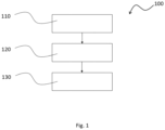
- Figure 1 shows a flowchart of an embodiment of a method 100 according to a first aspect of the invention.
- the installation method 100 shown is a method for installing a hob, in particular an induction hob, in a kitchen unit. For this purpose, it comprises the steps set out below.
- a first step 110 comprises providing a hob holder in a worktop of the kitchen furniture.
- a subsequent step 120 comprises providing at least one ventilation opening in a subfloor and/or in an intermediate floor of the kitchen furniture, wherein the ventilation opening is arranged in the region of a ventilation opening of the hob on a hob underside when the hob is installed.
- a final step 130 comprises inserting the hob into the hob receptacle of the worktop such that the ventilation opening of the hob is substantially above the correspondingly assigned ventilation opening.
- the three steps 110, 120, 130 form the core of the method according to the invention and are preferably carried out in this order.
- step 120 can be supplemented by further sub-steps because for several ventilation openings on the underside of the cooktop, several ventilation openings must be provided in the subfloor and/or the intermediate floor.
- Another additional step can be to provide a clearance on the back wall of the kitchen unit. This allows for better air circulation with ambient air and hot exhaust air can be led out of the kitchen unit.
- a further step of the method according to the invention can consist in providing a gap between the base and/or the intermediate floor of the kitchen furniture and the rear wall of the kitchen furniture. This enables better circulation of exhaust air and/or supply air through the kitchen furniture. This is particularly advantageous if the exhaust air and/or supply air escapes at least partially from the hob via openings arranged on the side and therefore cannot be guided directly through the ventilation openings.
- the ventilation openings, the clearance on the rear wall and/or the gap between the base and/or the intermediate floor of the kitchen unit and the rear wall can be provided at least partially by drilling and/or sawing. This allows the kitchen unit to be individually adapted to the hob.
- the various method steps are preferably carried out during a process of installing the hob in the kitchen furniture, but can be carried out at different times.
- the hob can be mounted as part of step 110 during the manufacture of the kitchen furniture, whereas the ventilation openings are only provided before a specific hob is inserted by manual steps such as drilling and/or sawing.
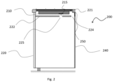
- Figure 2 shows a schematic representation of a first embodiment of a mounting system 200 according to a second aspect of the invention.
- the installation system 200 consists of a hob 210 and a kitchen furniture 220, which is provided by an installation method 100 according to the first aspect of the invention.
- an existing kitchen furniture was adapted to the hob 210 to be installed as part of the installation method 100 in order to bring about the ventilation of the kitchen furniture 220 according to the invention.
- the kitchen furniture 220 has at least one ventilation opening 225 provided in the region of a ventilation opening 215 on the underside of the hob 210.
- the ventilation opening 215 is an intake opening for drawing in fresh air, which is intended to cool the hob 210 during operation. Hot exhaust air is emitted in a ventilation opening (not shown) on the side of the hob 210 facing the user.
- the hob 210 was inserted in a predetermined orientation into the hob holder 224 provided in the kitchen furniture 220, in this case in a worktop 221 of the kitchen furniture 220.
- the ventilation opening 225 shown ensures direct intake of cooler air from the remaining volume of the kitchen furniture 220 and thus avoids intake of already preheated air from the exhaust air of the ventilation of the hob 210.
- the distance between the intermediate floor 222 and the cooking surface 210 is in the present case less than 4 cm, in particular less than 2 cm, particularly preferably less than 1.6 cm.
- a gap 250 is also provided between the intermediate floor 222 of the kitchen furniture 220 and the rear wall 240 of the kitchen furniture 220.
- the gap 250 extends over the entire width of the intermediate floor 222.
- a width of the gap 250 i.e. a distance between the intermediate floor 222 of the kitchen furniture 220 and the rear wall 240 of the kitchen furniture 220, is at least 1.5 cm, in particular at least 2.5 cm, preferably at least 4 cm.
- This gap 250 enables hot exhaust air to be discharged from the area between the hob 210 and the intermediate floor 222. This prevents heat from accumulating under the hob 210 and thereby heating up the hob 210 and/or an upper area of the kitchen furniture 220.
- the gap 250 is therefore complemented by the at least one ventilation opening 225 provided, since the ventilation opening allows direct intake of cool air from the remaining Kitchen furniture 220 and the gap 250 also guides hot exhaust air away from the hob.
- the installation system according to the invention therefore helps to effectively cool the hob 210.
- Ventilation openings in the hob can be air inlet openings, exhaust air openings or a combination of both.
- ventilation of the kitchen furniture for cooling the built-in hob is improved via the at least one ventilation opening.
- Figure 3 shows a schematic representation of a second embodiment of the installation system 300 according to the second aspect of the invention.
- the installation system 300 differs from the one in Fig. 2
- the built-in system 200 shown in FIG. 1 is characterized, among other things, by the fact that the hob 210 rests on a base 323. In contrast to the Fig. 2 In the intermediate floor 222 shown, there is therefore no distance between the hob 210 and the at least one ventilation opening 325. In this case, supply air is drawn directly from the remaining volume of the kitchen furniture 320 into the hob 210.
- Exhaust air from the hob 210 is blown out of the hob 210 through a side ventilation opening (not shown) and reaches the remaining volume of the kitchen unit 320 through the gap 250 so as not to contribute to heating directly at the hob 210.
- the installation system 300 differs from the one in Fig. 2 illustrated installation system 200 in that a clearance 360 is provided in the upper region of the rear wall 340 of the kitchen furniture 320.
- This clearance 360 has the form of a gap that extends over the entire width of the rear wall 340 and is at least 1.5 cm, preferably at least 2.5 cm, particularly preferably at least 4 cm wide.
- the position of the clearance 360 allows hot exhaust air to exit directly from the kitchen furniture 220 and thus additionally contribute to cooling the hob 210.
- moisture can escape from the kitchen furniture 320.
- an offset between the rear wall 340 and the room wall 370 is also provided in order to allow ventilation through the clearance 360.
- This offset is created by the fact that the rear wall 340 of the kitchen furniture 320 is set back in such a way that when the worktop 321 of the kitchen furniture 320 rests against the room wall 370, there is a distance between the rear wall 340 and the room wall 370 that is at least 1.5 cm, in particular at least 2.5 cm, preferably at least 4 cm.
- Such a distance from the rear wall allows particularly reliable ventilation of the kitchen furniture 320 via the clearance 360, the gap 350 and the at least one ventilation opening 325.
- Figure 4 shows a schematic representation of a third embodiment of the installation system 400 according to the second aspect of the invention.
- the installation system 400 differs from the one in Fig. 3 illustrated installation system 300 in that an intermediate floor 422 is used in the kitchen furniture 420, i.e. there is a distance between the hob 210 and the intermediate floor 422.
- a pipe 480 is attached to the at least one ventilation opening 215 of the hob 210 on the underside of the hob, which reduces a distance between the ventilation opening 225 and the associated ventilation opening 215.
- the pipe lies directly on the ventilation opening 225.
- a distance is provided between the pipe and the ventilation opening.
- the pipe is arranged directly on the intermediate floor and not on the hob.
- the pipe is attached to both the hob and the intermediate floor as part of the installation process.
- the pipe 480 enables a strict separation between the air supplied to the hob 210 and the exhaust air discharged from the hob.
- the supply air and exhaust air can only meet below the intermediate floor 422 in the remaining volume of the kitchen unit 420. This makes it particularly efficient to avoid the intake of warmed exhaust air for cooling the hob 210.
- a seal can be provided on the side of the pipe facing away from the hob 210 in order to enable a reliable separation of supply air and exhaust air directly below the hob even in the event of any unevenness of the intermediate floor 422.
Landscapes
- Engineering & Computer Science (AREA)
- Chemical & Material Sciences (AREA)
- Combustion & Propulsion (AREA)
- Mechanical Engineering (AREA)
- General Engineering & Computer Science (AREA)
- Ventilation (AREA)
Applications Claiming Priority (1)
| Application Number | Priority Date | Filing Date | Title |
|---|---|---|---|
| BE20235500A BE1031725B1 (de) | 2023-06-19 | 2023-06-19 | Einbauverfahren zum Einbau eines Kochfeldes |
Publications (1)
| Publication Number | Publication Date |
|---|---|
| EP4481276A1 true EP4481276A1 (fr) | 2024-12-25 |
Family
ID=88412964
Family Applications (1)
| Application Number | Title | Priority Date | Filing Date |
|---|---|---|---|
| EP24178485.9A Withdrawn EP4481276A1 (fr) | 2023-06-19 | 2024-05-28 | Procédé d'installation d'une plaque de cuisson |
Country Status (2)
| Country | Link |
|---|---|
| EP (1) | EP4481276A1 (fr) |
| BE (1) | BE1031725B1 (fr) |
Citations (5)
| Publication number | Priority date | Publication date | Assignee | Title |
|---|---|---|---|---|
| US4983799A (en) * | 1988-12-27 | 1991-01-08 | Compagnie Europeenne Pour L'equipement Menager-Cepem | Device for supporting the control means for a domestic appliance |
| US20080017630A1 (en) * | 2006-07-18 | 2008-01-24 | Bsh Bosch Und Siemens Hausgerate Gmbh | Protective device for a heating unit |
| KR100829629B1 (ko) * | 2007-01-23 | 2008-05-16 | 엘지전자 주식회사 | 빌트 인 가열조리기기 |
| US20100219179A1 (en) * | 2009-03-02 | 2010-09-02 | Delta Electronics, Inc. | Electrical apparatus and air circulating system having such electrical apparatus |
| WO2023081964A1 (fr) * | 2021-11-15 | 2023-05-19 | I.C.V. Induction Cooktop Vents Pty. Ltd. | Ensemble de ventilation pour table de cuisson |
-
2023
- 2023-06-19 BE BE20235500A patent/BE1031725B1/de active IP Right Grant
-
2024
- 2024-05-28 EP EP24178485.9A patent/EP4481276A1/fr not_active Withdrawn
Patent Citations (5)
| Publication number | Priority date | Publication date | Assignee | Title |
|---|---|---|---|---|
| US4983799A (en) * | 1988-12-27 | 1991-01-08 | Compagnie Europeenne Pour L'equipement Menager-Cepem | Device for supporting the control means for a domestic appliance |
| US20080017630A1 (en) * | 2006-07-18 | 2008-01-24 | Bsh Bosch Und Siemens Hausgerate Gmbh | Protective device for a heating unit |
| KR100829629B1 (ko) * | 2007-01-23 | 2008-05-16 | 엘지전자 주식회사 | 빌트 인 가열조리기기 |
| US20100219179A1 (en) * | 2009-03-02 | 2010-09-02 | Delta Electronics, Inc. | Electrical apparatus and air circulating system having such electrical apparatus |
| WO2023081964A1 (fr) * | 2021-11-15 | 2023-05-19 | I.C.V. Induction Cooktop Vents Pty. Ltd. | Ensemble de ventilation pour table de cuisson |
Also Published As
| Publication number | Publication date |
|---|---|
| BE1031725B1 (de) | 2025-02-03 |
| BE1031725A1 (de) | 2025-01-27 |
Similar Documents
| Publication | Publication Date | Title |
|---|---|---|
| EP3504483B1 (fr) | Appareil combiné et appareil de cuisine comprenant cet appareil combiné | |
| DE4328995C2 (de) | Reinraumanlage | |
| EP3499145B1 (fr) | Arrangement d'un dispositif de mise en température d'un espace sous un plafond | |
| DE3879507T2 (de) | Luft-verteilungsanordnung. | |
| BE1031725B1 (de) | Einbauverfahren zum Einbau eines Kochfeldes | |
| DE10233672A1 (de) | Belüftungsvorrichtung für mit Kühlcontainern zu beladende Laderäume | |
| DE102019101029B4 (de) | Isolierpaneel, Komponente eines Fahrzeugaufbaus, Fahrzeugaufbau, Fahrzeug und Herstellungsverfahren | |
| DE69305538T2 (de) | Klimagerät | |
| DE20108669U1 (de) | Kühlanordnung | |
| EP3285017B1 (fr) | Panneau de plafond radiant chauffant et rafraîchissant comprenant au moins un ventilateur | |
| DE19525945C2 (de) | Verfahren und Vorrichtung zur Erzeugung behaglicher Raumluftzustände | |
| DE10191092B3 (de) | Bausatz für einen Schaltschrank | |
| EP2051017A2 (fr) | Dispositif de climatisation de pièces | |
| DE102016117380A1 (de) | Schaltschrankkühlgerät mit einem Kondensatabscheider | |
| DE1918446A1 (de) | Beheizbarer Fussboden | |
| DE102011100211A1 (de) | System aus Deckenstrahlplatten und Gebäude hiermit | |
| DE202008010063U1 (de) | Lufttechnische Einrichtung | |
| EP1312868B1 (fr) | Agencement d'une plaque de cuisson et d'un fond intermédiaire et fond intermédiaire | |
| EP4193096B1 (fr) | Unité de ventilation forcée pour ventiler une chambre à air fermée | |
| WO2020057986A1 (fr) | Lampe destinée à être montée dans un plafond | |
| WO2008046587A2 (fr) | Ensembles de poste de travail | |
| DE2349388A1 (de) | Einbauherd | |
| EP2258991A2 (fr) | Dispositif d'aération | |
| DE3329365A1 (de) | Verfahren zur kuehlung thermisch hochbelasteter raeume und anordnung zur durchfuehrung des verfahrens | |
| EP1544550A2 (fr) | Installation de chauffage par le sol |
Legal Events
| Date | Code | Title | Description |
|---|---|---|---|
| PUAI | Public reference made under article 153(3) epc to a published international application that has entered the european phase |
Free format text: ORIGINAL CODE: 0009012 |
|
| STAA | Information on the status of an ep patent application or granted ep patent |
Free format text: STATUS: THE APPLICATION HAS BEEN PUBLISHED |
|
| AK | Designated contracting states |
Kind code of ref document: A1 Designated state(s): AL AT BE BG CH CY CZ DE DK EE ES FI FR GB GR HR HU IE IS IT LI LT LU LV MC ME MK MT NL NO PL PT RO RS SE SI SK SM TR |
|
| STAA | Information on the status of an ep patent application or granted ep patent |
Free format text: STATUS: REQUEST FOR EXAMINATION WAS MADE |
|
| 17P | Request for examination filed |
Effective date: 20250625 |
|
| STAA | Information on the status of an ep patent application or granted ep patent |
Free format text: STATUS: THE APPLICATION IS DEEMED TO BE WITHDRAWN |
|
| 18D | Application deemed to be withdrawn |
Effective date: 20250626 |