EP4481309A1 - Four de calcination indirecte idc - Google Patents
Four de calcination indirecte idc Download PDFInfo
- Publication number
- EP4481309A1 EP4481309A1 EP23180086.3A EP23180086A EP4481309A1 EP 4481309 A1 EP4481309 A1 EP 4481309A1 EP 23180086 A EP23180086 A EP 23180086A EP 4481309 A1 EP4481309 A1 EP 4481309A1
- Authority
- EP
- European Patent Office
- Prior art keywords
- duct
- conduit
- calciner
- inlet
- outlet
- Prior art date
- Legal status (The legal status is an assumption and is not a legal conclusion. Google has not performed a legal analysis and makes no representation as to the accuracy of the status listed.)
- Pending
Links
Images




Classifications
-
- F—MECHANICAL ENGINEERING; LIGHTING; HEATING; WEAPONS; BLASTING
- F27—FURNACES; KILNS; OVENS; RETORTS
- F27B—FURNACES, KILNS, OVENS OR RETORTS IN GENERAL; OPEN SINTERING OR LIKE APPARATUS
- F27B7/00—Rotary-drum furnaces, i.e. horizontal or slightly inclined
- F27B7/20—Details, accessories or equipment specially adapted for rotary-drum furnaces
- F27B7/2016—Arrangements of preheating devices for the charge
- F27B7/2025—Arrangements of preheating devices for the charge consisting of a single string of cyclones
- F27B7/2033—Arrangements of preheating devices for the charge consisting of a single string of cyclones with means for precalcining the raw material
-
- C—CHEMISTRY; METALLURGY
- C04—CEMENTS; CONCRETE; ARTIFICIAL STONE; CERAMICS; REFRACTORIES
- C04B—LIME, MAGNESIA; SLAG; CEMENTS; COMPOSITIONS THEREOF, e.g. MORTARS, CONCRETE OR LIKE BUILDING MATERIALS; ARTIFICIAL STONE; CERAMICS; REFRACTORIES; TREATMENT OF NATURAL STONE
- C04B7/00—Hydraulic cements
- C04B7/36—Manufacture of hydraulic cements in general
- C04B7/43—Heat treatment, e.g. precalcining, burning, melting; Cooling
Definitions
- the invention relates to a calciner for a cement clinker plant.
- the calciner comprises a first duct with a first raw meal inlet and a first raw meal outlet being in fluid communication via a first duct volume.
- the calciner further comprises a first conduit with a first heat carrier fluid inlet and a first heat carrier fluid outlet being in fluid communication via a first conduit volume.
- Cement clinker is an important intermediate product in Portland Cement manufacturing.
- limestone and additives are ground in a so-called raw mill, homogenized, and subsequently preheated using kiln exhaust gas.
- the preheated raw meal is calcined, i.e., decarbonized. This calcination takes place at temperatures of about 900°C in a so called calciner.
- the calciner is usually a gas-solid direct heat exchanger, i.e. a heat exchanger in which a heat carrier fluid is in direct contact with the raw meal to be heated.
- the hot calcined raw meal exits the calciner and is transported by the fumes produced in the calciner (fume jet transport) to a cyclone. In the cyclone, the hot calcined raw meal is separated from the fumes and falls down into the raw-meal inlet of the kiln.
- the CO 2 emission of the cement clinker process is in part inherent to the process, as limestone (CaCO 3 ) is calcined into lime (CaO) in the calciner, thereby releasing CO 2 .
- the corresponding chemical reaction is described by the formula CaCO 3 + heat ⁇ CaO + CO 2 and is thus an endothermal chemical reaction.
- This reaction is herein referred to as calcination or decarbonization.
- Another portion of the CO 2 is produced by burning fuel to provide the thermal energy driving the above endothermic calcination in the calciner, to sinter the lime with the other constituents of the raw meal to clinker in the kiln and to produce the electrical power for operating the plant.
- approximately 50-60% of the released CO 2 are released in the calcination step.
- the other approximately 50-40% are released by said burning fuel (see e.g., Johanna Lehne and Felix Preston, Making Concrete Change Innovation in Low-carbon Cement and Concrete, Chatham House Report, London 2018 ).
- These other 50-40% of the CO 2 -emission can at least in principle be avoided by using sustainable fuels and/or simply so called "green" electricity.
- the CaL consists essentially of capturing CO 2 in flue gases by an exothermal reaction of the CO 2 with CaO to CaCO 3 .
- the reaction reads CaO + CO 2 ⁇ CaCO 3 +heat, is thus exothermal and referred to as carbonation.
- the CaCO 3 is decarbonized (i.e., calcined) in a calciner, thereby releasing CO 2 and CaO, enabling to thereby obtain at least essentially pure CO 2 .
- the CO 2 can be stored, e.g., in geological formations (commonly referred to as CO 2 -sequestration) or used in other processes. In any case it is not released to the environment.
- the CaO can be subjected to carbonation, again.
- the CaL can be integrated into the cement clinker process, i.e., the calciner for (pre-)calcination of the raw meal is the source of the CaO being required in the carbonation step of the CaL.
- the CaCO 3 obtained in the carbonation step is subsequently provided to the calciner to obtain fresh CaO, i.e., a portion of the CaO/CaCO 3 circles in the process.
- the calciner is necessarily an indirect heat exchanger for heating the CaCO 3 , i.e. a heat exchanger in which the heat source and the CaCO 3 remain separated and are only in thermal contact. This enables to remove almost pure CO 2 from the calciner.
- This almost pure CO 2 can be stored or used for other industrial or agricultural purposes.
- a first portion of the calcined raw meal is provided to the kiln to complete the transformation of the raw meal into clinker.
- the remaining portion of the calcined raw meal is provided to a carbonator.
- the CaO in the calcined raw meal reacts with the CO 2 contained in the flue gases from the kiln to CaCO 3 .
- the flue gases from the kiln are thus subjected to CO 2 -removal.
- the CO 2 being bound in CaCO 3 produced in the carbonator is added to the raw meal entering the calciner, where the CO 2 is released.
- the problem to be solved by the invention is to provide an indirect heat exchange calciner.
- the invention provides a calciner for a cement clinker manufacturing line.
- an indirect heat exchange calciner is provided.
- the heat source is a heat carrier fluid.
- the heat carrier fluid can be hot kiln exhaust gas, a tertiary air stream and/or fuel being burnt in the calciner.
- the calciner comprises at least a first raw meal duct ('duct' for short) with a first raw meal inlet and a first raw meal outlet being in fluid communication via a first duct volume.
- the duct is configured to provide a first raw meal flow from the first duct inlet to the first duct outlet via a first duct volume.
- the duct's raw meal inlet and a raw meal outlet are referred to as duct inlet and duct outlet, respectively.
- 'First' is used only as denominator to distinguish from optional second, third, ... n th , ducts.
- the calciner may further comprise at least a first conduit with a first heat carrier fluid inlet and a first heat carrier fluid outlet (for short: conduit inlet and conduit outlet, respectively).
- the first conduit inlet and the first conduit outlet are in fluid communication via a first conduit volume.
- the first conduit is configured to provide a first heat carrier fluid flow from the first conduit inlet to the first conduit outlet.
- First' is used only as denominator to distinguish from optional second, third, ... m th , conduits.
- the first duct volume is delimited (at least partially) by the first duct facing surface of a first wall and the conduit volume is delimited (at least partially) by a first conduit facing surface of said at least one first wall.
- the first wall is thus in between of the duct volume and the conduit volume and separates the duct volume and the conduit volume from each other, while being configured to provide a thermal connection.
- heat being provided to the calciner by the heat carrier fluid heats the wall up and the heated wall then transfers heat to the raw meal.
- the CaCO 3 in the raw meal decomposes into CaO and CO 2 .
- the previously uncalcined raw meal is converted into calcined raw meal.
- the calcined raw meal may be provided to a raw meal inlet of a kiln.
- the first wall may comprise or consist of a first wall material.
- the first wall has a first surface at a first side and a second surface at as second side.
- the two sides face in opposite directions.
- the wall material may include or consist of a refractory and/or mineral building materials like ceramic, concrete, brick, etc. and can generally be described as a preferably inorganic and preferably non-metallic building material.
- the first wall provides a support structure and at the same time is a heat transfer element.
- sheet metal was used in indirect calciners to separate the duct and the conduit, however, in the temperature range at or above 1100°C, sheet metal constructions become soft and instable. Further, the metal was subjected to abrasion due to the raw-meal flow and by particles being transported by the heat carrier fluid (e.g. kiln dust). The walls of mineral material, however, remain solid at these elevated temperatures and thus provide a self-supporting structure being much cheaper than sheet metal constructions requiring additional support structures and/or expensive alloys. Further, longevity is enhanced as well.
- the heat carrier fluid e.g. kiln dust
- the calciner preferably has a second wall with a second duct facing surface and a second conduit facing surface.
- the second duct facing surface preferably delimits the first duct as well.
- the second wall allows to increase the heat transfer to the raw meal in the first duct.
- the calciner may further comprise a second conduit with a second heat carrier fluid inlet and a second heat carrier fluid outlet being in fluid communication via a second conduit volume.
- the second conduit facing surface may delimit the second conduit.
- the i th of the at least l - 2 duct facing surfaces is separated by the i th of the at least l - 2 wall materials from the i th of the at least l - 2 conduit facing surfaces.
- the calciner may comprise a number of n ducts wherein preferably ⁇ 2 ⁇ 1 ⁇ n and each of the n ducts are/is delimited by at least two of the at least l - 2 duct facing surfaces.
- the calciner may preferably further comprise a number of m conduits, wherein at least l /2 - 1 ⁇ m conduits are delimited by at least two of the at least l - 2 conduit facing surfaces.
- n ducts, m conduits and l walls provide a very efficient heat exchange with reduced cost of construction.
- the heat carrier flow through two conduits contributes to heating the raw meal in the duct in between of the two conduits that so to speak embrace the duct.
- At least the first duct has at least one Carbon Dioxide outlet.
- each of the n ducts, or at least a subset of the n ducts has at least one Carbon Dioxide outlet.
- the Carbon Dioxide outlet (CO 2 outlet) may be connected to a dust collector.
- Example dust collectors are electrostatic precipitators, inertial separators, filters, settling chambers, etc.
- the optional dust collector is hence configured to receive a CO 2 -stream comprising the CO 2 being released in the calcination process and raw meal dust.
- the optional dust collector is further configured to separate raw meal dust from a gaseous fraction comprising the CO 2 .
- the separated raw meal dust may be provided by a conveyor to the duct inlet, to the duct outlet and/or to a kiln's raw meal inlet and/or to a carbonation reactor.
- the gaseous fraction comprises preferably mainly CO 2 , i.e. the CO 2 being released in the calcination process.
- Other constituents of the gaseous fraction can be reduced by preheating the raw meal prior to providing it to the duct inlet, wherein the preheating temperature should be below the calcination temperature. Thereby, other components that enter the gas phase slightly below the calcination temperature can be separated from the CO 2 being released in the calcination step.
- the optionally dedusted CO 2 -stream exiting the at least one CO 2 outlet is preferably provided to an inlet of a (preferably indirect) heat exchanger and used to preheat a second heat carrier fluid and/or raw meal.
- at least one CO 2 -outlet of the calciner is preferably connected to a hot gas inlet of a raw meal preheater or of a heat carrier fluid preheater and/ or a steam boiler.
- CO 2 is cooled down and the thereby released thermal energy is recuperated and can be used as process energy.
- the first duct is a chute. This eases conveying the hot raw meal stream and provides for an effective heat exchange.
- the optional CO 2 outlet of the duct is located above the raw meal inlet. This measure reduces the amount of dust being removed from the duct via the CO 2 outlet and hence increases the CO 2 concentration in the CO 2 -stream.
- At least one of the conduit facing surfaces may have at least one, preferably multiple protrusions extending into the conduit. These protrusions increase the surface area of the conduit facing surface and thereby the heat transfer via the respective wall.
- these protrusions are preferably configured to disturb a laminar flow of the heat carrier fluid. In operation, these protrusions thereby mix cooled-down boundary layers of the heat carrier fluid with still hot inner 'layers' of the heat carrier fluid (assuming a laminar flow to be a stack of layers having different flow velocities) and thus improves the heat transfer further.
- the conduit may further comprise a fuel inlet.
- the fuel inlet turns the conduit into a reactor for combusting the fuel to thereby generate thermal energy being transferred via the wall(s) to the duct(s).
- the fuel inlet may itself be considered as a heat carrier fluid inlet, i.e. as the conduit inlet, as the energy provided to the conduit is provided by the fuel inlet. Conceptionally, it does not make a difference if the heat is generated in the conduit by burning fuel therein or if an already hot heat carrier fluid is provided via the conduit inlet to the conduit volume. Preferably, both alternatives are combined.
- an already hot heat carrier fluid can be a tertiary air stream being provided by a clinker cooler that may be mixed with a fuel.
- the conduit inlet may be connected to a tertiary air duct ( "duct" in tertiary air duct does not imply a raw meal flow; tertiary air ducts are known in the art and the term shall be understood accordingly, see e.g. US20130203005A1 .
- Tertiary air ducts are connections providing a preheated oxygen source (e.g. air) from a clinker cooler to a calciner.)
- the calciner is preferably a part of a cement clinker line, but may as well be used in other industrial fields, e.g. in a CaL-process.
- the cement clinker line may further comprise a kiln with a first end and a second end, wherein the first end comprises a calcined raw meal inlet and an exhaust gas outlet.
- the kiln's second end may comprise a hot clinker outlet.
- the hot clinker outlet may be configured to discharge hot clinker into a clinker cooler.
- the duct outlet is connected via a calcined raw meal conveyor with the kiln's calcined raw meal inlet.
- the kiln's exhaust gas outlet may be connected to the calciner's heat-carrier fluid inlet.
- the cement clinker line may further comprise a clinker cooler with a coolant inlet and a coolant outlet and with a hot clinker inlet configured to receive the hot clinker from the kiln.
- the cooler may further comprise a cool clinker outlet.
- the hot coolant outlet may be connected with the conduit's heat carrier inlet, e.g., via a tertiary air duct. This provides an efficient use of the energy recuperated from the hot cement clinker.
- a duct and a conduit both provide a fluid connection.
- the term duct is used if the connection is configured to provide a raw-meal flow and the term conduit is used if the connection is configured to provide flow of a heat-carrier fluid (exception: tertiary air duct as explained above).
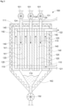
- Fig. 1 shows a first example of a calciner 100.
- the calciner has a number of n ducts 110.
- n 2, but this is only an example.
- Each duct has a raw meal inlet 111 and a raw meal outlet 112, being in fluid communication via a duct volume 113.
- the duct inlet 111 is above the duct outlet 112.
- Raw meal can be provided via at least one inlet feeder 131 to the duct inlet 111 and hence to the duct volume.
- the raw meal in the duct volumes 113 may be conveyed in a raw meal conveying direction 115 to the duct outlet 112 and may be removed from the calciner 100 via a duct outlet feeder 132.
- the ducts 110 are chutes configured to convey the raw meal due to gravity, but this is only a preferred example.
- the ducts 110 may further comprise a CO 2 outlet 114 being in fluid communication with the duct volume 113.
- Each conduit has a conduit inlet 121 and a conduit outlet 122. In between of the conduit inlet 121 and the conduit outlet is a conduit volume 123.
- the conduits 120 are configured to convey a heat-carrier fluid from the conduit inlets 121 via the conduit volumes 123 in a heat carrier fluid conveying direction 125 to the conduit outlets 122. In a preferred example the heat carrier flow direction 125 is opposite to the raw meal flow direction 115.
- Each duct volume 113 is delimited by at least one wall 140.
- These walls 140 may each have a duct facing surface 141 and a conduit facing surface 142.
- the two outer walls 140 have only a conduit facing surface 142, the opposite surface is preferably covered by an optional thermal insulation layer 150.
- the wall material is preferably a refractory and/or a mineral building material like ceramic, concrete, brick, stone etc. Generally, the material can be described as an inorganic and non-metallic building material.
- a heat-carrier fluid may be provided to the conduit inlets 121 and may be withdrawn via the conduit outlets 122.
- the heat carrier fluid may hence pass the conduit volume 123 and may be in direct contact with the conduit facing surfaces 142 of the walls 140.
- the walls 140 heat up and a heat flow towards the duct facing surface 141 of the wall 140 takes place, while raw meal being provided to the duct volume 113 via the duct inlet 111 passes along the duct facing surface 141 and is thereby heated up.
- This heat causes the CaCO 3 in the raw meal to decompose into CaO and CO 2 .
- the such obtained CO 2 can be withdrawn from the calciner via the CO 2 -outlet 114.
- the calcined raw meal falls down to the duct outlet 112 and may be removed from the calciner 100.
- the decomposition of the CaCO 3 provides 1 Mol of CO 2 per Mol CaCO 3 , and hence the volume of CO 2 being generated is huge compared to the volume of raw meal.
- the continuously released CO 2 provides a turbulent flow of CO 2 towards the CO 2 -outlet which improves the heat transfer from the duct facing surface 141 of the wall 140 to the CaCO 3 and results in a homogenization of the raw meal.
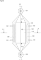
- FIG. 2 Another example of a calciner is shown in FIG. 2 .
- the description of FIG. 1 can be read on FIG. 2 as well, main differences will be described:
- the numbers of n ducts and m conduits are different as well as the number of inlet feeders 131 and outlet feeders 132.
- the multiple duct outlets 112 in FIG. 2 are connected to a single outlet feeder 132, while each duct inlet 111 is connected to a single inlet feeder 131, providing the advantage of enabling a good control over the raw-meal flow for each duct, while reducing the cost of installation by reducing the number of outlet feeders 132.
- the number of outlet feeders 132 is preferably not one to implement redundancy.
- the number of inlet feeders is preferably higher than (preferably at least equal to) the number of outlet feeders (not only in the embodiment of FIG. 2 , but preferably in any embodiment).
- Reference numeral 162 denotes already calcined raw meal, ready to be fed by outlet feed out of the calciner 100.
- FIG. 3 shows a structure 200 confining an example conduit 120 wherein one wall 140 has been removed to allow visual inspection of the conduit 120.
- the structure 200 hence may have two walls 140 each with conduit facing surface 142. Lands 220 in between of the two walls 140 delimit the conduit 120 perpendicular to the normal direction of the walls 140 and define the extension of the conduit in the normal direction of the conduit facing surface 142 of the wall 140.
- the structure 200 may be located next to a duct volume 113 (see e.g. FIG. 1 ), to thereby confine by at least one of the walls 140 the duct volume 113 towards the conduit 120 (see e.g. Fig. 1 ).
- the conduit 120 may be delimited by a conduit facing surface 142 of a wall 140.
- the conduit 120 may comprise a conduit inlet 121 and/or a conduit outlet 122.
- the conduit inlet 121 is located in a bottom side 210 of the structure 200 and/or in the lower half of a narrow side of the structure 200 (as depicted).
- the conduit outlet 122 is preferably located in the upper land 220 or as shown in the upper half of a narrow facing side of the structure 200.
- the lands 220 may have protrusions 222 extending into the conduit volume 123.
- the protrusions 222 slow the heat carrier fluid's flow speed down (for a given pressure gradient between the conduit inlet 121 and the conduit outlet 122) and already thereby increase the heat transfer from a heat carrier fluid flowing from conduit inlet 121 to the conduit outlet 122 to the wall 140.
- the protrusions transform an otherwise at least essentially laminar heat-carrier fluid flow to become at least more turbulent.
- at least one protrusion may have at least one heat-fluid flow stall edge.
- Another type of protrusions 230 may extend from the wall 140 into the volume 123. These protrusions 230 as well improve the heat conduction from the heat carrier fluid to the wall 140.
- FIG. 4 Another example of a calciner is shown in FIG. 4 (comprising FIG. 4A and 4B ).
- the description of FIG. 1 and 2 can as well be read on FIG. 4 , main differences will be described: While the examples in FIG. 1 and FIG. 2 have an essentially rectangular horizontal section, the example in FIG. 4 has a round (preferably circular) structure: A single duct 110 is surrounded by a number of conduits 120. The wall 140 may be unitary or comprise stacks as indicated.
- FIG. 5 shows a simplified cement clinker line 1 with a calciner 100. Any of the above described calciners 100 can be used. Sintering of precalcined raw meal to cement clinker may take place in a kiln 40.
- the optional kiln 40 has a first end with a calcined raw meal inlet (see end of calcined raw meal line) and an exhaust gas outlet, providing the exhaust gas to an exhaust gas outlet 45.
- the sintered cement clinker is discharged at the second end into a cement clinker cooler 50.
- the calciner 100 may have a calcined raw meal outlet being connected by a calcined raw meal line 105 with the kiln's calcined raw meal inlet.
- the calciner 100 may further comprise a heat carrier fluid inlet 102, being in fluid communication with at least one conduit inlet 121 (cf. FIG. 1 to 4B ).
- the calciner 100 may further comprise a raw meal inlet 101 being optionally connected by an optional preheated raw meal line 26 with an optional raw meal preheater 20.
- Raw meal may be provided to the cement clinker line 1 via a raw meal inlet 21, providing the raw meal, e.g. to the raw meal preheater 20.
- exhaust gas being an example for a heat carrier fluid
- tertiary air see tertiary air duct 55
- Other heat sources may of course be used as well.
- the cement clinker line 1 may further comprise an optional carbonator 30.
- the carbonator 30 may be connected by a calcined raw meal line 107 with the calciner 100 and may hence receive calcined raw meal from the calciner 100.
- the calcined raw meal may be reacted with CO 2 being comprised in the exhaust gas (e.g. kiln exhaust gas) to CaCO 3 .
- the exhaust gas may be provided by an exhaust gas line 25 from an exhaust gas outlet of the preheater 20 and/or an exhaust gas port of an optional Cl-bypass treatment unit 60, which may be configured to remove Chlorine and/or heavy metals from the process.
- the CO 2 depleted exhaust gas may be provided via an optional depleted exhaust gas line 35 to an optional exhaust gas treatment facility 70 and/or may be released as indicated by an arrow leaving the exhaust gas treatment facility 70.
- the CaCO 3 being produced in the carbonator 30 may be provided via an optional CaCO 3 line to the preheater 20 and/or or the calciner 100 and hence be used to manufacture clinker and/or to provide CaO as required for operating the carbonator 30.
Landscapes
- Engineering & Computer Science (AREA)
- Chemical & Material Sciences (AREA)
- Ceramic Engineering (AREA)
- Physics & Mathematics (AREA)
- Thermal Sciences (AREA)
- Materials Engineering (AREA)
- Structural Engineering (AREA)
- Organic Chemistry (AREA)
- Mechanical Engineering (AREA)
- General Engineering & Computer Science (AREA)
- Furnace Details (AREA)
Priority Applications (2)
| Application Number | Priority Date | Filing Date | Title |
|---|---|---|---|
| EP23180086.3A EP4481309A1 (fr) | 2023-06-19 | 2023-06-19 | Four de calcination indirecte idc |
| PCT/EP2024/066831 WO2024260928A1 (fr) | 2023-06-19 | 2024-06-17 | Calcinateur indirect idc |
Applications Claiming Priority (1)
| Application Number | Priority Date | Filing Date | Title |
|---|---|---|---|
| EP23180086.3A EP4481309A1 (fr) | 2023-06-19 | 2023-06-19 | Four de calcination indirecte idc |
Publications (1)
| Publication Number | Publication Date |
|---|---|
| EP4481309A1 true EP4481309A1 (fr) | 2024-12-25 |
Family
ID=86899198
Family Applications (1)
| Application Number | Title | Priority Date | Filing Date |
|---|---|---|---|
| EP23180086.3A Pending EP4481309A1 (fr) | 2023-06-19 | 2023-06-19 | Four de calcination indirecte idc |
Country Status (2)
| Country | Link |
|---|---|
| EP (1) | EP4481309A1 (fr) |
| WO (1) | WO2024260928A1 (fr) |
Citations (8)
| Publication number | Priority date | Publication date | Assignee | Title |
|---|---|---|---|---|
| EP0656071B1 (fr) * | 1992-08-21 | 1997-06-11 | Maschinenfabrik Niehoff Gmbh & Co. Kg | Procede et dispositif de regulation de la puissance calorifique d'une installation de recuit au passage de produits metalliques coules en continu |
| JP2004231424A (ja) * | 2003-01-28 | 2004-08-19 | Aienji:Kk | 間接加熱式石灰炉 |
| FR2921059A1 (fr) | 2007-09-14 | 2009-03-20 | Rech S Geol Et Minieres Brgm E | Procede et installation de production de clinker |
| US20130203005A1 (en) | 2011-08-24 | 2013-08-08 | Ikn Gmbh | Clinker kiln with slider for tertiary air duct |
| EP2701121A1 (fr) * | 2012-07-06 | 2014-02-26 | Chugai Ro Co., Ltd. | Dispositif de chauffage continu |
| CN104797352A (zh) * | 2012-10-19 | 2015-07-22 | 尼霍夫机器制造公司 | 在生产细长线状材料期间用于热传递的装置 |
| EP3074360A1 (fr) * | 2013-11-29 | 2016-10-05 | Calix Ltd | Procédé et appareil pour la fabrication de ciment portland |
| WO2022167424A1 (fr) * | 2021-02-05 | 2022-08-11 | Maschinenfabrik Niehoff Gmbh & Co. Kg | Dispositif de recuit continu de fil |
-
2023
- 2023-06-19 EP EP23180086.3A patent/EP4481309A1/fr active Pending
-
2024
- 2024-06-17 WO PCT/EP2024/066831 patent/WO2024260928A1/fr not_active Ceased
Patent Citations (9)
| Publication number | Priority date | Publication date | Assignee | Title |
|---|---|---|---|---|
| EP0656071B1 (fr) * | 1992-08-21 | 1997-06-11 | Maschinenfabrik Niehoff Gmbh & Co. Kg | Procede et dispositif de regulation de la puissance calorifique d'une installation de recuit au passage de produits metalliques coules en continu |
| JP2004231424A (ja) * | 2003-01-28 | 2004-08-19 | Aienji:Kk | 間接加熱式石灰炉 |
| FR2921059A1 (fr) | 2007-09-14 | 2009-03-20 | Rech S Geol Et Minieres Brgm E | Procede et installation de production de clinker |
| US20130203005A1 (en) | 2011-08-24 | 2013-08-08 | Ikn Gmbh | Clinker kiln with slider for tertiary air duct |
| EP2701121A1 (fr) * | 2012-07-06 | 2014-02-26 | Chugai Ro Co., Ltd. | Dispositif de chauffage continu |
| CN104797352A (zh) * | 2012-10-19 | 2015-07-22 | 尼霍夫机器制造公司 | 在生产细长线状材料期间用于热传递的装置 |
| EP3074360A1 (fr) * | 2013-11-29 | 2016-10-05 | Calix Ltd | Procédé et appareil pour la fabrication de ciment portland |
| EP3074360B1 (fr) * | 2013-11-29 | 2020-01-01 | Calix Ltd | Procédé pour la fabrication de ciment portland |
| WO2022167424A1 (fr) * | 2021-02-05 | 2022-08-11 | Maschinenfabrik Niehoff Gmbh & Co. Kg | Dispositif de recuit continu de fil |
Non-Patent Citations (1)
| Title |
|---|
| OLIVIERJANSSENS-MAENHOUTMUNTEANPETERS: "Trends in global C02 emissions: 2016 Report", THE HAGUE: PBL NETHERLANDS ENVIRONMENTAL ASSESSMENT AGENCY, 22 January 2020 (2020-01-22), pages 65, Retrieved from the Internet <URL:http://edar.jrc.ec.europa.eu/newsdocs/jrc-2016-trends-in-global-co2-emissions-2016-report-103425.pd> |
Also Published As
| Publication number | Publication date |
|---|---|
| WO2024260928A1 (fr) | 2024-12-26 |
Similar Documents
| Publication | Publication Date | Title |
|---|---|---|
| AU2007233570B2 (en) | System and method for the calcination of minerals | |
| AU2014354559B9 (en) | Process and apparatus for manufacture of portland cement | |
| US8617506B2 (en) | Method and facility for recovering CO2 gas in cement manufacturing facility | |
| EP2743241B1 (fr) | Procédé et système de récupération de gaz CO2 dans des installations de fabrication de ciment | |
| EP2461892B1 (fr) | Procédé de capture du co2 produit par des installations de production de ciment en utilisant le cycle du calcium | |
| CN1124998C (zh) | 减少窑装置NOx排放量的方法 | |
| CN113167531A (zh) | 无预热器废气再循环的氧燃料熟料生产 | |
| US8784097B2 (en) | Apparatus for the production of clinker from raw meal and relative process | |
| US4039277A (en) | Apparatus for calcining powder materials | |
| EP3865801A1 (fr) | Appareil et procédé de fabrication de clinker de ciment | |
| EP3738939A1 (fr) | Procédé de calcination de repas brut pour fabrication de clinker de ciment | |
| EP4481309A1 (fr) | Four de calcination indirecte idc | |
| CN119894842A (zh) | 用于过滤燃烧的方法和设备 | |
| RU2214570C2 (ru) | Установка для двухстадийного обжига гранулированных и зернистых материалов | |
| JP2024140141A (ja) | 二酸化炭素の回収設備及び回収方法、二酸化炭素の貯留方法、セメントクリンカの製造システム及び製造方法、並びにドライアイスの製造方法 | |
| JP2024039396A (ja) | セメント製造設備のco2回収システムおよびセメント製造設備のco2回収方法 | |
| WO2026080268A1 (fr) | Calcination en boucle fermée à l'aide de dioxyde de carbone chauffé | |
| WO2026028121A1 (fr) | Système pour le traitement thermique de matière en vrac solide | |
| BR112019008730A2 (pt) | método para produzir materiais em pó nanoativos em um reator | |
| JP2024039393A (ja) | セメント製造設備のco2回収システムおよびセメント製造設備のco2回収方法 | |
| JP2001294456A (ja) | 熱処理装置 | |
| JPS6051642A (ja) | セメント原料粉末の仮焼方法 | |
| BR112019008730B1 (pt) | Método e sistema de reator para produzir um material em pó nanoativo | |
| CN87100766A (zh) | 粉状原料的热制备装置 | |
| JPS5857382B2 (ja) | セメント原料用仮焼炉を含むセメント焼成装置 |
Legal Events
| Date | Code | Title | Description |
|---|---|---|---|
| PUAI | Public reference made under article 153(3) epc to a published international application that has entered the european phase |
Free format text: ORIGINAL CODE: 0009012 |
|
| STAA | Information on the status of an ep patent application or granted ep patent |
Free format text: STATUS: REQUEST FOR EXAMINATION WAS MADE |
|
| 17P | Request for examination filed |
Effective date: 20240507 |
|
| AK | Designated contracting states |
Kind code of ref document: A1 Designated state(s): AL AT BE BG CH CY CZ DE DK EE ES FI FR GB GR HR HU IE IS IT LI LT LU LV MC ME MK MT NL NO PL PT RO RS SE SI SK SM TR |
|
| GRAJ | Information related to disapproval of communication of intention to grant by the applicant or resumption of examination proceedings by the epo deleted |
Free format text: ORIGINAL CODE: EPIDOSDIGR1 |
|
| GRAP | Despatch of communication of intention to grant a patent |
Free format text: ORIGINAL CODE: EPIDOSNIGR1 |
|
| GRAP | Despatch of communication of intention to grant a patent |
Free format text: ORIGINAL CODE: EPIDOSNIGR1 |
|
| STAA | Information on the status of an ep patent application or granted ep patent |
Free format text: STATUS: GRANT OF PATENT IS INTENDED |
|
| INTG | Intention to grant announced |
Effective date: 20251219 |
|
| GRAS | Grant fee paid |
Free format text: ORIGINAL CODE: EPIDOSNIGR3 |
|
| GRAJ | Information related to disapproval of communication of intention to grant by the applicant or resumption of examination proceedings by the epo deleted |
Free format text: ORIGINAL CODE: EPIDOSDIGR1 |
|
| GRAL | Information related to payment of fee for publishing/printing deleted |
Free format text: ORIGINAL CODE: EPIDOSDIGR3 |
|
| STAA | Information on the status of an ep patent application or granted ep patent |
Free format text: STATUS: REQUEST FOR EXAMINATION WAS MADE |