EP4481322A1 - Verfahren zur durchführung einer qualitätskontrolle eines herzustellenden bauteils einer windenergieanlage - Google Patents
Verfahren zur durchführung einer qualitätskontrolle eines herzustellenden bauteils einer windenergieanlage Download PDFInfo
- Publication number
- EP4481322A1 EP4481322A1 EP23180346.1A EP23180346A EP4481322A1 EP 4481322 A1 EP4481322 A1 EP 4481322A1 EP 23180346 A EP23180346 A EP 23180346A EP 4481322 A1 EP4481322 A1 EP 4481322A1
- Authority
- EP
- European Patent Office
- Prior art keywords
- component
- data
- geometry data
- bearing
- ring
- Prior art date
- Legal status (The legal status is an assumption and is not a legal conclusion. Google has not performed a legal analysis and makes no representation as to the accuracy of the status listed.)
- Withdrawn
Links
Images



Classifications
-
- G—PHYSICS
- G01—MEASURING; TESTING
- G01B—MEASURING LENGTH, THICKNESS OR SIMILAR LINEAR DIMENSIONS; MEASURING ANGLES; MEASURING AREAS; MEASURING IRREGULARITIES OF SURFACES OR CONTOURS
- G01B11/00—Measuring arrangements characterised by the use of optical techniques
- G01B11/24—Measuring arrangements characterised by the use of optical techniques for measuring contours or curvatures
- G01B11/25—Measuring arrangements characterised by the use of optical techniques for measuring contours or curvatures by projecting a pattern, e.g. one or more lines, moiré fringes on the object
- G01B11/2518—Projection by scanning of the object
-
- G—PHYSICS
- G01—MEASURING; TESTING
- G01B—MEASURING LENGTH, THICKNESS OR SIMILAR LINEAR DIMENSIONS; MEASURING ANGLES; MEASURING AREAS; MEASURING IRREGULARITIES OF SURFACES OR CONTOURS
- G01B11/00—Measuring arrangements characterised by the use of optical techniques
- G01B11/24—Measuring arrangements characterised by the use of optical techniques for measuring contours or curvatures
- G01B11/25—Measuring arrangements characterised by the use of optical techniques for measuring contours or curvatures by projecting a pattern, e.g. one or more lines, moiré fringes on the object
-
- G—PHYSICS
- G01—MEASURING; TESTING
- G01B—MEASURING LENGTH, THICKNESS OR SIMILAR LINEAR DIMENSIONS; MEASURING ANGLES; MEASURING AREAS; MEASURING IRREGULARITIES OF SURFACES OR CONTOURS
- G01B11/00—Measuring arrangements characterised by the use of optical techniques
- G01B11/002—Measuring arrangements characterised by the use of optical techniques for measuring two or more coordinates
-
- G—PHYSICS
- G01—MEASURING; TESTING
- G01N—INVESTIGATING OR ANALYSING MATERIALS BY DETERMINING THEIR CHEMICAL OR PHYSICAL PROPERTIES
- G01N21/00—Investigating or analysing materials by the use of optical means, i.e. using sub-millimetre waves, infrared, visible or ultraviolet light
- G01N21/84—Systems specially adapted for particular applications
- G01N21/88—Investigating the presence of flaws or contamination
- G01N21/95—Investigating the presence of flaws or contamination characterised by the material or shape of the object to be examined
- G01N21/9515—Objects of complex shape, e.g. examined with use of a surface follower device
- G01N2021/9516—Objects of complex shape, e.g. examined with use of a surface follower device whereby geometrical features are being masked
Definitions
- the present invention relates to a method for performing a quality control of a component of a wind turbine to be produced.
- the tolerance of the shape of these components can be crucial. This will be explained exemplarily with the help of the case where the component is a ring of a contact ball bearing or contact roller bearing.
- Such rings typically comprise a raceway where balls or rollers are guided.
- the correct shape of the profiles of the raceway ensures that excessive contact pressures are avoided. If the respective shape deviates too much from an ideal shape, a blockage of the bearing or at least an excessive wear and, hence, a reduced lifetime of the bearing can occur. As a consequence, it is extremely important to perform a quality control regarding the tolerances of the geometry or shape of the component.
- several approaches to perform respective quality controls are known.
- CMM coordinate measuring machine
- this object is achieved by a method as initially described, wherein geometry data which provide a 3D-model of an actual shape of at least a part of the component are collected using a measuring device being a non-contact 3D-scanner, wherein deviations between the actual shape and an ideal shape of the at least one part of the component are detected using the geometry data.
- the geometry data describe the geometric shape or, in other words, the extents or dimensions of the component or, more precisely, of the outer surface of the component to provide the 3D-model.
- the 3D-model describes the actual, i.e., the real shape of the component.
- the gained 3D-model comprises a high data quality and allows for a fast processing.
- the present invention realizes a sophisticated approach to detect unwanted deviations between the actual shape and the ideal shape and, hence, possible defaults with respect to a given tolerance. Particularly, there is the possibility to automatize the data processing to simply the quality control.
- a simplification is further achieved by the fact that collecting data by the 3D-scanner requires a very low effort, particularly since a non-contact 3D-scanner is used such that no direct or physical contact between the component and a sensor element of the respective scanner is required.
- Raw data obtained by the measuring device can be transferred to a computer for further processing, analyses and evaluations.
- a software which is implemented on the computer can be used for this process.
- the geometry data can be the raw data or gained by processing or preparing the raw data.
- the ideal shape specifies a reference shape of the component.
- the actual shape equals the ideal shape if no deviations would be present or if the tolerance would be perfectly complied.
- the ideal shape can be provided or defined by the shape of an ideal geometric figure, e.g., a cuboid, a sphere, a cylinder, a cone, or a combination of these figures.
- the component can be a bearing or a member of a bearing of the wind turbine. As it has already been described, particularly for these components it is crucial that the actual shape is within a given tolerance range.
- the bearing can be a blade pitch bearing, a main bearing or a yaw bearing for example.
- the blade pitch bearing acts as a mechanical interface between a hub and a blade of the wind turbine.
- An inner ring or an outer ring of the bearing can be attached to the hub and the blade can be attached to the respective other ring.
- the blade pitch bearing allows for rotating the respective blade around its longitudinal axis.
- the member of the bearing being the component can be a ring of a contact ball bearing or of a contact roller bearing.
- These bearings typically comprise one or more inner rings and one or more outer rings which are arranged concentric to each other.
- the ring can comprise at least one raceway which extends along a circumference of the ring, wherein the geometry data provide the 3D-model of the shape of the ring at least for a section of the ring where the at least one raceway is arranged.
- the raceway can be also called as a guiding groove and typically comprises a longitudinal direction which extends along the circumferential direction of the ring.
- At least one raceway is typically provided on an outer surface of the inner ring and at least one raceway is typically provided on an inner surface of the outer ring.
- Balls or rollers are arranged between the raceways being opposed to each other to allow a relative rotation of the rings around their central axes.
- the ring or each of the rings comprises two raceways which extend parallel to each other.
- the raceway typically comprises a circular shape.
- the raceway typically comprises a rectangular shape.
- the 3D-scanner used can be an optical scanner or a laser scanner. Hence, particularly electromagnetic, radiation which is reflected or emitted by the component is detected by the 3D-scanner, wherein the respective data is used to gain the geometry data.
- the 3D-scanner can be an active scanner. In other words, the 3D-scanner can emit radiation which is reflected by the component, wherein the reflected radiation is detected by the 3D-scanner to obtain the geometry data. If the 3D-scanner is a laser scanner, the respective pulse transit time and/or phase differences can be used to obtain the geometry data.
- the 3D-scanner can be a passive scanner. In other words, the 3D-scanner can detect radiation which is reflected or emitted by the component which has not initially been created and emitted by the 3D-scanner. The radiation which is reflected by the component and not emitted by the 3D-scanner can be sunlight.
- the 3D-scanner being an optical scanner can comprise several optical cameras to obtain the geometry data being a three-dimensional picture of the component.
- the 3D-scanner can be handheld or mounted on a stand during the collection of the geometry data.
- a portable 3D-scanner is used such that no need to transport the component to a respective scanning location is required.
- the handheld 3D-scanner can be guided along the component by scanning personnel.
- the 3D-scanner can be attached on the stand, particularly on a tripod or another suitable holding device.
- the geometry data consist of a point cloud and/or a polygon mesh.
- the points of the point cloud or nodal points of the polygon mesh can comprise three coordinates which correspond to the three spatial directions.
- the respective coordinates correspond to a specific reference coordinate system, wherein the origin of coordinates can be the location of the 3D-scanner or another suitable point in the space, for instance a central point of the component.
- a transformation of coordinates can be performed, particularly to minimize the numbers which described the coordinates.
- the point cloud consists of data points which are arranged on a grid having a specified, particularly equally distributed, resolution.
- the data points can be provided by coordinates of a Cartesian coordinate system.
- the grid can be defined as evenly or equally distributed values regarding two coordinates, particularly the x- and the y-coordinate, wherein the third coordinate, particularly the z-coordinated, provides the position of the surface of the component.
- the data points can be evenly distributed regarding the x-y-plane.
- the geometry data which provide the 3D-model of the actual shape of at least a part of the component being ring-like can be transformed into adjusted geometry data, wherein the adjusted geometry data provide an adjusted 3D-model of the actual shape of at least a part of the component.
- a circumferential rounding of the component can be turned into a straight extent.
- the component is particularly the ring of the bearing which has been described above.
- the geometry data are transformed such that the circular shape of the component, particularly of the ring and, hence, of the raceway, is transformed into a straight shape.
- the relative positions between the data points, particularly of the points of the point cloud, and the points of the circumferential line can be held or kept.
- the adjusted geometry data are suitable for a simplified further processing or analysis, respectively.
- At least one data subset which provides a 2D-model of the shape of at least a part of the cross section of the component is extracted from the geometry data or from data obtained by the geometry data, particularly from the adjusted geometry data, wherein the deviations are detected using the at least one data subset.
- the at least one data subset provides a slice or plane of the component which is suitable for a simplified further processing or analysis, respectively.
- several data subsets are extracted, wherein the data subsets provide 2D-models of the shape of at least a part of the cross sections of the component along a certain direction, particularly longitudinal extent, of the component. If the component is ring-like, several data subsets can be extracted from the adjusted geometry data such that the data subsets provide 2D-models of the shape of at least a part of the cross sections of the component along the circumferential extent of the component.
- a function which describes the ideal shape can be fitted to the geometry data or to data obtained by the geometry data, particularly to the data subset or to the data subsets, wherein the results for the best fit are used to obtain the deviations.
- the fit can be performed by applying a method of minimizing the chi-square value.
- the function can describe a circle in the region of the at least one raceway.
- the function can describe a rectangle in the region of the at least one raceway.
- the deviations can be obtained by deviations between the geometry data or the data obtained by the geometry data and the best fit function.
- the deviations between the geometry data or the data obtained by the geometry data and the best fit function can be provided by the value of the, particularly reduced, chi-square. The larger the respective chi-square value, the larger is the deviation at the respective position.
- the deviations between the geometry data or the data obtained by the geometry data and the best fit function can be used to identify potentially problematic positions or sections of the component.
- the deviations can be obtained by at least one best fit result of the best fit function.
- the result for at least one fit parameter of the best fit function particularly the deviation between this result and the expected value for the respective fit parameter which corresponds to the ideal shape, acts as an indicator for the present deviation between the actual shape and the ideal shape.
- Fig. 1 shows a principal sketch of a wind turbine 1 comprising a tower 2, wherein on top of the tower a nacelle 3 is arranged. Furthermore, the wind turbine 1 comprises a hub 4, on which several, namely three, blades 5 are arranged. For harvesting wind energy, the blades 5 interact with wind which in turn causes the hub 4 to rotate, wherein this rotation is transferred to a generator which is located within the nacelle 3.
- the bearing 6 can be a contact roller bearing.
- the bearing 6 is a blade pitch bearing which acts as a mechanical interface between the hub 4 and the respective blade 5. The bearing 6 allows for rotating or tilting the respective blade 5 around its longitudinal axis 7.
- Fig. 2 shows an enlarged, three-dimensional and cut view of the bearing 6.
- the bearing 6 comprises two rings 8, namely an inner ring 8 and an outer ring 8.
- the rings 8 are arranged concentric to each other, wherein on an outer surface of the inner ring 8 and on an inner surface of the outer ring 8 face each other.
- two adjacent raceways 9 are provided which can be named as guiding grooves.
- Balls which are not shown in the figures, are arranged between two opposed raceways 9.
- Each of the raceways 9 extents along the circumference of the respective ring 8.
- the two raceways 9 of each of the rings 8 extend parallel to each other.
- the rings 8 can rotate around each other, wherein one of the ring 8 is connected with the hub 4 and the other ring 8 is connected with the blade 5.
- Fig. 3 shows a flow chart of this method, wherein the concrete embodiment of this method comprises the steps 10 to 16.
- the aim of the method is to perform a quality control of a component 17 of the wind turbine 1 to be produced, wherein the component 17 is a member or the bearing 6, namely the inner ring 8.
- the respective method can also be applied to other components of the wind turbine 1, particularly to the outer ring 8.
- the inner raceway 8 or component 17, respectively, and a non-contact 3D-scanner 18 are provided.
- the portable 3D-scanner 18 is mounted on a stand 19 being a tripod, wherein the 3D-scanner 18 is arranged beside the component 17.
- Theis situation is shown in fig. 4 , wherein only a part of the ring 8 is displayed. Instead of being mounted on the stand 19, the 3D-scanner 18 can be handheld by personnel during the subsequent procedure.
- the 3D-scanner 18 is an active scanner but can be also a passive scanner. Basically, the 3D-scanner 18 can be an optical scanner or a laser scanner. Referring to the situation shown in fig. 4 , the 3D-scanner 18 is an active laser scanner.
- the 3D-scanner 18 comprises a radiation source 20 being a laser source, wherein, during the next step 11 of the method, respective laser radiation 21 is emitted by the radiation source 20.
- the emitted radiation 21 is reflected by the component 17, wherein a radiation- or laser detector 22 of the 3D-scanner 18 detects the reflected radiation 23.
- geometry data 24 which provide a 3D-model of the actual shape of the component 17 are obtained and transferred to a computer for further processing.
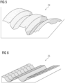
- fig. 5 shows a diagram or coordinate system with the geometry data 24.
- the 3D-model provided by the geometry data 24 consists of a point cloud. Additionally or alternatively, the geometry data 24 or 3D-model, respectively, can consist of a polygon mesh. As it becomes apparent from fig. 5 , the shape of the point cloud corresponds to the actual or real shape of the component 17, wherein particularly the raceways 9 become visible.
- the geometry data 24 provide a 3D-model of the section of the ring 8 which comprises the raceways 9 such that the geometry data 24 provide the geometric shape of the raceways 9.
- the geometry data 24 are subjected to a coordinated transformation such that the point of origin of the coordinate system corresponds to the central point of the ring 8.
- the axes of the coordinate system, on which the geometry data 24 are based are shifted.
- the geometry data 24 are transformed into adjusted geometry data 25.
- the adjusted geometry data 25 provide an adjusted 3D-model of the component 17 or raceway 9, respectively.
- the circumferential rounding which extends along the longitudinal direction of the raceways 9 is removed or, more precisely, turned into a straight extent.
- the geometry data 24 are adjusted such that a circumferential line of the ring 8 or raceways 9, respectively, is turned into a straight line, wherein the relative positions between the points of the point cloud and the points of the respective line are retained.
- the adjusted geometry data 25 is shown in fig. 6 which shows a diagram or coordinate system with the adjusted geometry data 25.
- the adjusted geometry data 25 consist of data points arranged on a grid having a specified and equally or evenly distributed resolution.
- each of the data subsets 26 provides a 2D-model of the shape of the cross-section of the ring 8 or of the raceways 9, respectively.
- the data subsets 26 provide cross-sectional cuts through the ring 8 or through the raceways 9, respectively, wherein these cuts are arranged equally spaced along the longitudinal extent of the raceways 9 and, hence, along the circumferential extent of the ring 8.
- Fig. 7 shows a diagram or coordinate system with one of the data subsets 26.
- step 15 a function which describes the ideal shape of the of the component 17 or raceways 9, respectively, is fitted to each of the data subsets 26, wherein the best fit results 27 are obtained.
- the best fit function is indicated by small circles in fig. 7 .
- the function is defined section by section and describes the ideal cross-sectional shape of the raceways 9, namely a circle each.
- the function can describe rectangles.
- Each of the best fit results 27 comprises the best fit parameters, e.g., the radii and central points of the fitted circles, and the respective chi-square value.
- step 16 a diagram which is shown in fig. 8 is output to evaluate the result of the quality control.
- the best fit results 27 are shown.
- the values of the best fit parameters and of the chi-square are plotted against the position of the respective data subsets 26 regarding the longitudinal extent of the raceways 9 and, hence, the circumferential extent of the ring 8.
- Positions where a large unevenness of the profile of the raceway 9 is present can be identified by the position on the x-axis of this diagram where large deviations between the best fit results 27 and respective values which are expected for the ideal shape are present and/or where the value of the chi-square is large or exceeds a given threshold value, respectively.
Landscapes
- Physics & Mathematics (AREA)
- General Physics & Mathematics (AREA)
- Engineering & Computer Science (AREA)
- Computer Vision & Pattern Recognition (AREA)
- Rolling Contact Bearings (AREA)
Priority Applications (5)
| Application Number | Priority Date | Filing Date | Title |
|---|---|---|---|
| EP23180346.1A EP4481322A1 (de) | 2023-06-20 | 2023-06-20 | Verfahren zur durchführung einer qualitätskontrolle eines herzustellenden bauteils einer windenergieanlage |
| CN202480040004.4A CN121336083A (zh) | 2023-06-20 | 2024-05-28 | 用于对要制造的风力涡轮机的部件执行品质控制的方法 |
| PCT/EP2024/064625 WO2024260687A1 (en) | 2023-06-20 | 2024-05-28 | Method for performing a quality control of a component of a wind turbine to be produced |
| KR1020257041917A KR20260020949A (ko) | 2023-06-20 | 2024-05-28 | 생산될 풍력 터빈의 컴포넌트의 품질 제어를 수행하기 위한 방법 |
| EP24730007.2A EP4680918A1 (de) | 2023-06-20 | 2024-05-28 | Verfahren zur durchführung einer qualitätskontrolle eines herzustellenden bauteils einer windenergieanlage |
Applications Claiming Priority (1)
| Application Number | Priority Date | Filing Date | Title |
|---|---|---|---|
| EP23180346.1A EP4481322A1 (de) | 2023-06-20 | 2023-06-20 | Verfahren zur durchführung einer qualitätskontrolle eines herzustellenden bauteils einer windenergieanlage |
Publications (1)
| Publication Number | Publication Date |
|---|---|
| EP4481322A1 true EP4481322A1 (de) | 2024-12-25 |
Family
ID=86903966
Family Applications (2)
| Application Number | Title | Priority Date | Filing Date |
|---|---|---|---|
| EP23180346.1A Withdrawn EP4481322A1 (de) | 2023-06-20 | 2023-06-20 | Verfahren zur durchführung einer qualitätskontrolle eines herzustellenden bauteils einer windenergieanlage |
| EP24730007.2A Pending EP4680918A1 (de) | 2023-06-20 | 2024-05-28 | Verfahren zur durchführung einer qualitätskontrolle eines herzustellenden bauteils einer windenergieanlage |
Family Applications After (1)
| Application Number | Title | Priority Date | Filing Date |
|---|---|---|---|
| EP24730007.2A Pending EP4680918A1 (de) | 2023-06-20 | 2024-05-28 | Verfahren zur durchführung einer qualitätskontrolle eines herzustellenden bauteils einer windenergieanlage |
Country Status (4)
| Country | Link |
|---|---|
| EP (2) | EP4481322A1 (de) |
| KR (1) | KR20260020949A (de) |
| CN (1) | CN121336083A (de) |
| WO (1) | WO2024260687A1 (de) |
Citations (3)
| Publication number | Priority date | Publication date | Assignee | Title |
|---|---|---|---|---|
| KR20150088925A (ko) * | 2014-01-24 | 2015-08-04 | (주)기흥기계 | 대형 베어링의 시편을 이용한 정밀도 측정 시스템 |
| EP3567340A1 (de) * | 2018-05-09 | 2019-11-13 | Siemens Gamesa Renewable Energy A/S | Sichtprüfungsanordnung |
| US20200124406A1 (en) * | 2017-05-08 | 2020-04-23 | Wobben Properties Gmbh | Method for referencing a plurality of sensors and associated measuring device |
-
2023
- 2023-06-20 EP EP23180346.1A patent/EP4481322A1/de not_active Withdrawn
-
2024
- 2024-05-28 CN CN202480040004.4A patent/CN121336083A/zh active Pending
- 2024-05-28 EP EP24730007.2A patent/EP4680918A1/de active Pending
- 2024-05-28 KR KR1020257041917A patent/KR20260020949A/ko active Pending
- 2024-05-28 WO PCT/EP2024/064625 patent/WO2024260687A1/en not_active Ceased
Patent Citations (3)
| Publication number | Priority date | Publication date | Assignee | Title |
|---|---|---|---|---|
| KR20150088925A (ko) * | 2014-01-24 | 2015-08-04 | (주)기흥기계 | 대형 베어링의 시편을 이용한 정밀도 측정 시스템 |
| US20200124406A1 (en) * | 2017-05-08 | 2020-04-23 | Wobben Properties Gmbh | Method for referencing a plurality of sensors and associated measuring device |
| EP3567340A1 (de) * | 2018-05-09 | 2019-11-13 | Siemens Gamesa Renewable Energy A/S | Sichtprüfungsanordnung |
Non-Patent Citations (1)
| Title |
|---|
| ANONYMOUS: "3D Measurement and Size Deviation Analysis Of 6-M Wind Power Blade", BLOG, 17 November 2018 (2018-11-17), CN, pages 1 - 9, XP055767384, Retrieved from the Internet <URL:https://www.shining3d.com/blog/3d-measurement-and-size-deviation-analysis-of-6-m-wind-power-blade/> [retrieved on 20210121] * |
Also Published As
| Publication number | Publication date |
|---|---|
| WO2024260687A1 (en) | 2024-12-26 |
| KR20260020949A (ko) | 2026-02-12 |
| EP4680918A1 (de) | 2026-01-21 |
| CN121336083A (zh) | 2026-01-13 |
Similar Documents
| Publication | Publication Date | Title |
|---|---|---|
| EP3168808B1 (de) | System zur automatischen messung von geformten kühlungsbohrungen | |
| Xu et al. | Near real-time circular tunnel shield segment assembly quality inspection using point cloud data: A case study | |
| KR102073803B1 (ko) | 3차원 표면조도 평가장치, 3차원 표면조도 평가방법, 3차원 표면조도 데이터 취득장치 및 3차원 표면조도 데이터 취득방법 | |
| US20170140515A1 (en) | Systems and methods for monitoring components | |
| US7768655B2 (en) | Methods and system for measuring an object | |
| EP3081899B1 (de) | Datenerfassungsvorrichtung und verfahren zur analyse von dehnungssensoren und überwachung von turbinenkomponentendehnung | |
| US10416097B2 (en) | Method of scanning aerofoil blades | |
| US7720649B2 (en) | Reverse engineering method for disk and blade attachments | |
| EP4481322A1 (de) | Verfahren zur durchführung einer qualitätskontrolle eines herzustellenden bauteils einer windenergieanlage | |
| Ghorbani et al. | Accurate registration of point clouds of damaged aeroengine blades | |
| Lyngby et al. | Development and metrological validation of a new automated scanner system for freeform measurements on wind turbine blades in the production | |
| JP2014169961A (ja) | 工具検査方法及び工具検査装置 | |
| Goessling et al. | High-speed Digital Image Correlation (DIC) for measuring deformation and vibration of fast rotating fan blades | |
| CN111023992A (zh) | 基于线结构光的截面曲线特征检测方法及其应用 | |
| Barone et al. | Optical tracking of a tactile probe for the reverse engineering of industrial impellers | |
| KR20150088925A (ko) | 대형 베어링의 시편을 이용한 정밀도 측정 시스템 | |
| US20200271440A1 (en) | Shape Measuring Device for Hose Connector Fitting, Shape Measuring Method for Hose Connector Fitting and Shape Measuring Program for Hose Connector Fitting | |
| CN108426558A (zh) | 被动应变指示器 | |
| JP2017096941A (ja) | 構成部品の歪を監視するためのシステムおよび方法 | |
| CN114987788B (zh) | 适用于飞机大部件的蒙皮端面的位置度检测方法 | |
| Zhang et al. | Large-scale shape measurement by a combined method based on three instruments | |
| Pivkin et al. | New promising approaches to the design of cutting tools based on the search for optimal control indicators | |
| Vukašinović et al. | Optical areal geometrical quality control of gears | |
| Wang et al. | Influence of incident angle on distance detection accuracy of point laser probe with charge-coupled device: prediction and calibration | |
| Chu et al. | Research on coaxiality error measurement methodology for rectangular spline shafts using 3D point cloud technology |
Legal Events
| Date | Code | Title | Description |
|---|---|---|---|
| PUAI | Public reference made under article 153(3) epc to a published international application that has entered the european phase |
Free format text: ORIGINAL CODE: 0009012 |
|
| STAA | Information on the status of an ep patent application or granted ep patent |
Free format text: STATUS: THE APPLICATION HAS BEEN PUBLISHED |
|
| AK | Designated contracting states |
Kind code of ref document: A1 Designated state(s): AL AT BE BG CH CY CZ DE DK EE ES FI FR GB GR HR HU IE IS IT LI LT LU LV MC ME MK MT NL NO PL PT RO RS SE SI SK SM TR |
|
| STAA | Information on the status of an ep patent application or granted ep patent |
Free format text: STATUS: THE APPLICATION IS DEEMED TO BE WITHDRAWN |
|
| 18D | Application deemed to be withdrawn |
Effective date: 20250626 |