EP4481365A1 - Dispositif de détection de gaz - Google Patents
Dispositif de détection de gaz Download PDFInfo
- Publication number
- EP4481365A1 EP4481365A1 EP24170480.8A EP24170480A EP4481365A1 EP 4481365 A1 EP4481365 A1 EP 4481365A1 EP 24170480 A EP24170480 A EP 24170480A EP 4481365 A1 EP4481365 A1 EP 4481365A1
- Authority
- EP
- European Patent Office
- Prior art keywords
- gas
- detection device
- plate
- loading region
- inlet
- Prior art date
- Legal status (The legal status is an assumption and is not a legal conclusion. Google has not performed a legal analysis and makes no representation as to the accuracy of the status listed.)
- Pending
Links
Images







Classifications
-
- G—PHYSICS
- G01—MEASURING; TESTING
- G01N—INVESTIGATING OR ANALYSING MATERIALS BY DETERMINING THEIR CHEMICAL OR PHYSICAL PROPERTIES
- G01N15/00—Investigating characteristics of particles; Investigating permeability, pore-volume or surface-area of porous materials
- G01N15/10—Investigating individual particles
- G01N15/14—Optical investigation techniques, e.g. flow cytometry
- G01N15/1456—Optical investigation techniques, e.g. flow cytometry without spatial resolution of the texture or inner structure of the particle, e.g. processing of pulse signals
-
- G—PHYSICS
- G01—MEASURING; TESTING
- G01N—INVESTIGATING OR ANALYSING MATERIALS BY DETERMINING THEIR CHEMICAL OR PHYSICAL PROPERTIES
- G01N15/00—Investigating characteristics of particles; Investigating permeability, pore-volume or surface-area of porous materials
- G01N15/06—Investigating concentration of particle suspensions
-
- F—MECHANICAL ENGINEERING; LIGHTING; HEATING; WEAPONS; BLASTING
- F04—POSITIVE - DISPLACEMENT MACHINES FOR LIQUIDS; PUMPS FOR LIQUIDS OR ELASTIC FLUIDS
- F04B—POSITIVE-DISPLACEMENT MACHINES FOR LIQUIDS; PUMPS
- F04B45/00—Pumps or pumping installations having flexible working members and specially adapted for elastic fluids
- F04B45/04—Pumps or pumping installations having flexible working members and specially adapted for elastic fluids having plate-like flexible members, e.g. diaphragms
- F04B45/047—Pumps having electric drive
-
- G—PHYSICS
- G01—MEASURING; TESTING
- G01D—MEASURING NOT SPECIALLY ADAPTED FOR A SPECIFIC VARIABLE; ARRANGEMENTS FOR MEASURING TWO OR MORE VARIABLES NOT COVERED IN A SINGLE OTHER SUBCLASS; TARIFF METERING APPARATUS; MEASURING OR TESTING NOT OTHERWISE PROVIDED FOR
- G01D21/00—Measuring or testing not otherwise provided for
- G01D21/02—Measuring two or more variables by means not covered by a single other subclass
-
- G—PHYSICS
- G01—MEASURING; TESTING
- G01N—INVESTIGATING OR ANALYSING MATERIALS BY DETERMINING THEIR CHEMICAL OR PHYSICAL PROPERTIES
- G01N1/00—Sampling; Preparing specimens for investigation
- G01N1/02—Devices for withdrawing samples
- G01N1/22—Devices for withdrawing samples in the gaseous state
-
- G—PHYSICS
- G01—MEASURING; TESTING
- G01N—INVESTIGATING OR ANALYSING MATERIALS BY DETERMINING THEIR CHEMICAL OR PHYSICAL PROPERTIES
- G01N15/00—Investigating characteristics of particles; Investigating permeability, pore-volume or surface-area of porous materials
- G01N15/06—Investigating concentration of particle suspensions
- G01N15/075—Investigating concentration of particle suspensions by optical means
-
- G—PHYSICS
- G01—MEASURING; TESTING
- G01N—INVESTIGATING OR ANALYSING MATERIALS BY DETERMINING THEIR CHEMICAL OR PHYSICAL PROPERTIES
- G01N33/00—Investigating or analysing materials by specific methods not covered by groups G01N1/00 - G01N31/00
- G01N33/0004—Gaseous mixtures, e.g. polluted air
- G01N33/0009—General constructional details of gas analysers, e.g. portable test equipment
-
- G—PHYSICS
- G01—MEASURING; TESTING
- G01N—INVESTIGATING OR ANALYSING MATERIALS BY DETERMINING THEIR CHEMICAL OR PHYSICAL PROPERTIES
- G01N15/00—Investigating characteristics of particles; Investigating permeability, pore-volume or surface-area of porous materials
- G01N2015/0042—Investigating dispersion of solids
- G01N2015/0046—Investigating dispersion of solids in gas, e.g. smoke
-
- G—PHYSICS
- G01—MEASURING; TESTING
- G01N—INVESTIGATING OR ANALYSING MATERIALS BY DETERMINING THEIR CHEMICAL OR PHYSICAL PROPERTIES
- G01N15/00—Investigating characteristics of particles; Investigating permeability, pore-volume or surface-area of porous materials
- G01N15/10—Investigating individual particles
- G01N15/14—Optical investigation techniques, e.g. flow cytometry
- G01N2015/1486—Counting the particles
-
- G—PHYSICS
- G01—MEASURING; TESTING
- G01N—INVESTIGATING OR ANALYSING MATERIALS BY DETERMINING THEIR CHEMICAL OR PHYSICAL PROPERTIES
- G01N33/00—Investigating or analysing materials by specific methods not covered by groups G01N1/00 - G01N31/00
- G01N33/0004—Gaseous mixtures, e.g. polluted air
- G01N33/0009—General constructional details of gas analysers, e.g. portable test equipment
- G01N33/0027—General constructional details of gas analysers, e.g. portable test equipment concerning the detector
- G01N33/0036—General constructional details of gas analysers, e.g. portable test equipment concerning the detector specially adapted to detect a particular component
- G01N33/0047—Organic compounds
-
- G—PHYSICS
- G01—MEASURING; TESTING
- G01N—INVESTIGATING OR ANALYSING MATERIALS BY DETERMINING THEIR CHEMICAL OR PHYSICAL PROPERTIES
- G01N33/00—Investigating or analysing materials by specific methods not covered by groups G01N1/00 - G01N31/00
- G01N33/0004—Gaseous mixtures, e.g. polluted air
- G01N33/0009—General constructional details of gas analysers, e.g. portable test equipment
- G01N33/0062—General constructional details of gas analysers, e.g. portable test equipment concerning the measuring method or the display, e.g. intermittent measurement or digital display
- G01N33/0063—General constructional details of gas analysers, e.g. portable test equipment concerning the measuring method or the display, e.g. intermittent measurement or digital display using a threshold to release an alarm or displaying means
-
- G—PHYSICS
- G01—MEASURING; TESTING
- G01N—INVESTIGATING OR ANALYSING MATERIALS BY DETERMINING THEIR CHEMICAL OR PHYSICAL PROPERTIES
- G01N33/00—Investigating or analysing materials by specific methods not covered by groups G01N1/00 - G01N31/00
- G01N33/0004—Gaseous mixtures, e.g. polluted air
- G01N33/0009—General constructional details of gas analysers, e.g. portable test equipment
- G01N33/0062—General constructional details of gas analysers, e.g. portable test equipment concerning the measuring method or the display, e.g. intermittent measurement or digital display
- G01N33/0068—General constructional details of gas analysers, e.g. portable test equipment concerning the measuring method or the display, e.g. intermittent measurement or digital display using a computer specifically programmed
Definitions
- the present disclosure relates to a gas detection device, and more particularly to an extremely thin gas detection device applied to arrange in an indoor air pollution prevention system for detecting gas, and instantly transmitting an air quality information to the system, thereby the indoor space can be cleaned to a safe and breathable state.
- Suspended particles are solid particles or droplets contained in the air. Since the sizes of the suspended particles are really small, the suspended particles may enter the lungs of human body through the nasal hair in the nasal cavity easily, causing inflammation in the lungs, asthma or cardiovascular disease. If other pollutants are attached to the suspended particles, it will further increase the harm to the respiratory system. In recent years, the problem of air pollution is getting worse. In particular, the concentration of particle matters (e.g., PM2.5) is often too high. Therefore, the monitoring to the concentration of the gas suspended particles is taken seriously. However, the gas flows unstably due to variable wind direction and air volume, and the general gas-quality monitoring station is located in a fixed place. Under this circumstance, it is impossible for people to check the concentration of suspended particles in current environment.
- concentration of particle matters e.g., PM2.5
- gas detection device it is feasible to use a gas detection device to monitor the air quality in the environment. If the gas detection device is capable of providing people with the monitored information relating to the environment immediately for warning, it may help people to escape or prevent from the injuries and influence on human health caused by the exposure to the gases and substances described above in the ambient environment. In other words, gas detection device is suitable for monitoring the air in the ambient environment.
- One object of the present disclosure is to provide a gas detection device, wherein an external connector, a power converter, a control processing board, a networking module and a particle detection module are accommodated in the housing to form a thin and portable device that is easy to carry. Since the external connector is plug-and-play, when it is plugged in an indoor power supply, the particle detection module starts detecting the suspended particles (e.g., PM1, PM2.5, or PM10) in the gas and the temperature and humidity sensor starts detecting the temperature and humidity in the environment.
- the detected data information can be transmitted to a cloud processing device through the IOT communication by the networking module.
- the detected data information can not only be transmitted as warnings or notifications on the indoor display device, but also on the mobile device application (APP).
- the detected data information can be compared through intelligent comparison and big data comparison of the cloud processing device.
- the cloud processing device sends communication commands to the indoor gas cleaning and exchange filtering devices (such as purifiers, exhaust fans, range hoods, fresh air fans, etc.), so as to effectively remove the indoor air pollution.
- the gas detection device is constructed for detecting gas in an indoor air pollution prevention system, and instantly transmits the air quality information to the system, so as to achieve a clean and safe breathing gas state.
- a gas detection device comprises a housing, an external connector, a power converter, a control processing board, a networking module and a particle detection module.
- the housing includes an upper housing and a lower housing, wherein a plurality of vents are arranged on an side edge of the lower housing, a lug hole is arranged on a lower side of the lower housing, and a recessed groove formed on a bottom surface of the lower housing.
- the external connector pivotally connects to the lower housing. When not in use, the external connector is folded and hidden in the recessed groove without protruding, when in use, the external connector is rotated out the recessed groove to expose out the lower case, and connects to an external power supply.
- the power converter electrically connects to the external connector, and converts the external power supply into a DC power.
- the control processing board electrically connects to the power converter for providing an activation power supply, and receiving and processing a plurality of data information to convert into a communication information.
- the networking module is disposed on a side of the upper housing, and is integrally packaged on the control processing board to form an integrated circuit. Also, the networking module receives and outputs the communication information processed by the control processing board.
- the particle detection module is disposed and positioned on the other side of the bottom surface of the lower housing, and is also adjacent to an opposite side of the networking module packaged on the control processing board.
- the particle detection module electrically connects to the control processing board through a first flexible band to detect gas and acquires the data information of the gas, and transmits the data information to the control processing board to convert into the communication information.
- the control processing board outputs the communication information through the networking module.
- the temperature and humidity sensor is disposed on a side of the lower housing, and electrically connects to the control processing board through a second flexible band for detecting temperature and humidity, and acquires the data information of the temperature and humidity. The data information of the temperature and humidity is transmitted to the control processing board to convert into the communication information, and the communication information is outputted through the networking module by the control processing board.
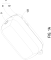
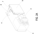
- the present disclosure provides a gas detection device, which includes a housing 1, an external connector 2, a power converter 3, a control processing board 4, a networking module 5, a particle detection module 6, and a temperature and humidity sensor 7.
- the above-mentioned housing 1 comprises an upper housing 11 and a lower housing 12, wherein the power converter 3, the control processing board 4, the networking module 5, the particle detection module 6, and the temperature and humidity sensor 7 are disposed between the upper housing 11 and the lower housing 12.
- a plurality of vents 122 are arranged on an side edge of the lower housing 12 for introducing gas within the housing 1 or discharging gas outside the housing 1, a lug hole 123 is arranged on a lower side of the lower housing 12, and a recessed groove 121 is formed on a bottom surface of the lower housing 12.
- the external connector 2 pivotally connects to the lower housing 12. When not in use, the external connector 2 is folded and hidden in the recessed groove 121 without protruding (as shown in FIG.
- the external connector 2 when in use, the external connector 2 is rotated out the recessed groove 121 to expose out the lower housing 12 (as shown in FIG. 1B ) and connect to an external power supply.
- a locking element passes through the lug hole 123 and is locked into a socket (not shown), so as to position the entire gas detection device. In this circumstance, the gas detection device is positioned, and is not easy to be touched or tripped.
- the external connector 2 is one selected from the group consisting of a power connector, a USB port, a mini-USB port, a Micro-USB port and a Type-C USB port.
- the external connector 2 as shown in FIG. 1B is a power connector.
- the power converter 3 is electrically connected to the external connector 2, and converted the external power supply into a DC power.
- the power converter 3 and the networking module 5 are integrally packaged on the control processing board 4 to form an integrated circuit.
- the control processing board 4 electrically connects to the power converter 3 for providing an activation power supply, and receives and processes a plurality of data information to convert into a communication information.
- the networking module 5 is disposed on the inner side of the upper housing 11 for receiving and outputting the communication information processed by the control processing board 4.
- the particle detection module 6 is disposed and positioned on the other side of the bottom surface of the lower housing 12, and is also adjacent to the opposite side of the networking module 5 packaged on the control processing board 4.
- the particle detection module 6 electrically connects to the control processing board 4 through a first flexible band to detect gas and acquire the data information of the gas, transmits the data information to the control processing board 4 to convert into the communication information, and then, the control processing board 4 outputs the communication information through the networking module 5.
- the temperature and humidity sensor 7 is disposed on the side of the lower housing 12, which can be disposed in any position on the other side of the bottom surface of the lower housing 12, for example, the side edge or the lower side of the inner surface of the lower housing 12.
- the temperature and humidity sensor 7 is disposed on the side edge of the inner surface of the lower housing 12, which is adjacent the particle detection module 6 and between the particle detection module 6 and the plurality of the vents 122.
- the temperature and humidity sensor 7 electrically connects to the control processing board 4 through a second flexible board for detecting temperature and humidity, and acquires the data information of the temperature and humidity, wherein the data information is transmitted to the control processing board 4 to convert into the communication information, and the communication information is outputted through the networking module 5 by the control processing board 4.
- the external connector 2 connects to an external power supply, so as to provide power to the power the power converter 3.
- the power is converted into a DC power and transmitted to the control processing board 4 by the power converter, and then provided to the networking module 5, the particle detection module 6, and the temperature and humidity sensor 7 for use and activation.
- the flexible band is a transmission connection cable required for electrical connection of electronic components.
- the following flexible band 8 can be a first flexible band, a second flexible band, etc., which are arranged to connect the particle detection module 6 and the temperature and humidity sensor 7, respectively.
- the particle detection module 6 electrically connected to the control processing board 4 through the first flexible band
- the temperature and humidity sensor 7 is electrically connected to the control processing board 4 through the second flexible band.
- the control processing board 4 also electrically connects to a switch 9.
- the switch 9 is exposed outside the upper housing 11 for the user to press, so that the control processing board 4 can supply the activation power supply to activate and control the operation of the networking module 5, the particle detection module 6 and the temperature and humidity sensor 7.
- the networking module 5 is for activating the internet of things (IOT) communication, but not limited thereto.
- the particle detection module 6 is for detecting the suspended particles (e.g., PM1, PM2.5, or PM10) in the gas, but not limited thereto.
- the temperature and humidity sensor 7 is for detecting the temperature and humidity in the ambient environment.
- the networking module 5 is a WIFI communication module.
- the networking module 5 is a cloud computing service wireless network communication module, such as Amazon Web Services (AWS), but not limited thereto.
- the networking module 5 is disposed on the side of the upper housing 11, which exposes outside the gas detection device. In this circumstance, it is easy to receive or send communication signals, and the networking module 5 is not easy to be shielded by the control processing board 4 and cause interference to the communication signals.
- the above-mentioned particle detection module 6 includes a base 61, a piezoelectric actuator 62, a driving circuit board 63, a laser component 64, a particulate sensor 65, and an outer cover 66.
- the driving circuit board 63 covers and is attached to a second surface 612 of the base 61
- the laser component 64 is positioned and disposed on the driving circuit board 63, and is electrically connected to the driving circuit board 63.
- the particulate sensor 65 is positioned and disposed on the driving circuit board 63, and is electrically connected to the driving circuit board 63.
- the outer cover 66 covers the base 61 and is attached to a first surface 611 of the base 61. Moreover, the outer cover 66 includes a side plate 661.
- the side plate 661 has an inlet opening 661a and an outlet opening 661b.
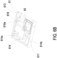
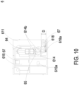
- the base 61 includes a first surface 611, a second surface 612, a laser loading region 613, a gas-inlet groove 614, a gas-guiding-component loading region 615 and a gas-outlet groove 616.
- the first surface 611 and the second surface 612 are two surfaces opposite to each other.
- the laser loading region 613 is hollowed out from the first surface 611 toward the second surface 612.
- the gas-inlet groove 614 is concavely formed from the second surface 612 and disposed adjacent to the laser loading region 613.
- the gas-inlet groove 614 includes a gas-inlet 614a and two lateral walls.
- the gas-inlet 614a is in communication with an environment outside the base 61, and is spatially corresponding in position to the inlet opening 661a of the outer cover 66.
- Two transparent windows 614b are opened on the two lateral walls of the gas-inlet groove 614 and are in communication with the laser loading region 613. Therefore, the first surface 611 of the base 61 is covered and attached by the outer cover 66, and the second surface 612 is covered and attached by the driving circuit board 63, so that an inlet path is defined by the gas-inlet groove 614.
- the above-mentioned gas-guiding-component loading region 615 is concavely formed from the second surface 612 and in communication with the gas-inlet groove 614.
- a ventilation hole 615a penetrates a bottom surface of the gas-guiding-component loading region 615.
- the gas-outlet groove 616 includes a gas-outlet 616a, and the gas-outlet 616a is spatially corresponding to the outlet opening 661b of the outer cover 66.
- the gas-outlet groove 616 includes a first section 616b and a second section 616c.
- the first section 616b is concavely formed out from the first surface 611 in a region spatially corresponding to a vertical projection area of the gas-guiding-component loading region 615.
- the second section 616c is hollowed out from the first surface 611 to the second surface 612 in a region where the first surface 611 is extended from the vertical projection area of the gas-guiding-component loading region 615.
- the first section 616b and the second section 616c are connected to form a stepped structure.
- the first section 616b of the gas-outlet groove 616 is in communication with the ventilation hole 615a of the gas-guiding-component loading region 615
- the second section 616c of the gas-outlet groove 616 is in communication with the gas-outlet 616a.
- the laser component 64 and the particulate sensor 65 are disposed on and electrically connected to the driving circuit board 63 and located within the base 61.
- the driving circuit board 63 is intentionally omitted in FIG. 5 .
- the laser component 64 is accommodated in the laser loading region 613 of the base 61
- the particulate sensor 65 is accommodated in the gas-inlet groove 614 of the base 61 and is aligned to the laser component 64.
- the laser component 64 is spatially corresponding to the transparent window 614b, therefore, a light beam emitted by the laser component 64 passes through the transparent window 614b and is irradiated into the gas-inlet groove 614.
- a light beam path emitted from the laser component 64 passes through the transparent window 614b and extends in an orthogonal direction perpendicular to the gas-inlet groove 614.
- a projecting light beam emitted from the laser component 64 passes through the transparent window 614b and enters the gas-inlet groove 614 to irradiate the suspended particles contained in the gas passing through the gas-inlet groove 614.
- the scattered light spots are received and calculated by the particulate sensor 65 to obtain the gas detection data.
- the particulate sensor 65 is a PM2.5 sensor.
- the piezoelectric actuator 62 is accommodated in the gas-guiding-component loading region 615 of the base 61.
- the gas-guiding-component loading region 615 is square and includes four positioning protrusions 615b disposed at four corners of the gas-guiding-component loading region 615, respectively.
- the piezoelectric actuator 62 is disposed in the gas-guiding-component loading region 615 through the four positioning protrusions 615b.
- the gas-guiding-component loading region 615 is in communication with the gas-inlet groove 614.
- the piezoelectric actuator 62 When the piezoelectric actuator 62 is enabled, the gas in the gas-inlet groove 614 is inhaled by the piezoelectric actuator 62, so that the gas flows into the piezoelectric actuator 62. Furthermore, the gas is transported into the gas-outlet groove 616 through the ventilation hole 615a of the gas-guiding-component loading region 615.
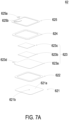
- the piezoelectric actuator 62 includes a gas-injection plate 621, a chamber frame 622, an actuator element 623, an insulation frame 624 and a conductive frame 625.
- the gas-injection plate 621 is made by a flexible material and includes a suspension plate 621a and a hollow aperture 621b.
- the suspension plate 621a is a sheet structure and is permitted to undergo a bending deformation.
- the shape and the size of the suspension plate 621a are accommodated in the inner edge of the gas-guiding-component loading region 615, but not limited thereto.
- the shape of the suspension plate 621a is selected from the group consisting of a square, a circle, an ellipse, a triangle and a polygon, but not limited thereto.
- the hollow aperture 621b passes through a center of the suspension plate 621a, so as to allow the gas to flow therethrough.
- the chamber frame 622 is carried and stacked on the gas-injection plate 621.
- the shape of the chamber frame 622 is corresponding to the gas-injection plate 621.
- the actuator element 623 is carried and stacked on the chamber frame 622.
- a resonance chamber 626 is collaboratively defined by the actuator element 623, the chamber frame 622 and the suspension plate 621a and is formed between the actuator element 623, the chamber frame 622 and the suspension plate 621a.
- the insulation frame 624 is carried and stacked on the actuator element 623 and the appearance of the insulation frame 624 is similar to that of the chamber frame 622.
- the conductive frame 625 is carried and stacked on the insulation frame 624, and the appearance of the conductive frame 625 is similar to that of the insulation frame 624.
- the conductive frame 625 includes a conducting pin 625a and a conducting electrode 625b.
- the conducting pin 625a is extended outwardly from an outer edge of the conductive frame 625
- the conducting electrode 625b is extended inwardly from an inner edge of the conductive frame 625.
- the actuator element 623 further includes a piezoelectric carrying plate 623a, an adjusting resonance plate 623b and a piezoelectric plate 623c.
- the piezoelectric carrying plate 623a is carried and stacked on the chamber frame 622.
- the adjusting resonance plate 623b is carried and stacked on the piezoelectric carrying plate 623a.
- the piezoelectric plate 623c is carried and stacked on the adjusting resonance plate 623b.
- the adjusting resonance plate 623b and the piezoelectric plate 623c are accommodated in the insulation frame 624.
- the conducting electrode 625b of the conductive frame 625 is electrically connected to the piezoelectric plate 623c.
- the piezoelectric carrying plate 623a and the adjusting resonance plate 623b are made by a conductive material.
- the piezoelectric carrying plate 623a includes a piezoelectric pin 623d.
- the piezoelectric pin 623d and the conducting pin 625a are electrically connected to a driving circuit (not shown) of the driving circuit board 63, so as to receive a driving signal, such as a driving frequency and a driving voltage.
- a circuit is formed by the piezoelectric pin 623d, the piezoelectric carrying plate 623a, the adjusting resonance plate 623b, the piezoelectric plate 623c, the conducting electrode 625b, the conductive frame 625 and the conducting pin 625a for transmitting the driving signal.
- the insulation frame 624 is insulated between the conductive frame 625 and the actuator element 623, so as to avoid the occurrence of a short circuit. Thereby, the driving signal is transmitted to the piezoelectric plate 623c.
- the piezoelectric plate 623c After receiving the driving signal such as the driving frequency and the driving voltage, the piezoelectric plate 623c deforms due to the piezoelectric effect, and the piezoelectric carrying plate 623a and the adjusting resonance plate 623b are further driven to generate the bending deformation in the reciprocating manner.
- the driving signal such as the driving frequency and the driving voltage
- the adjusting resonance plate 623b is located between the piezoelectric plate 623c and the piezoelectric carrying plate 623a and served as a cushion between the piezoelectric plate 623c and the piezoelectric carrying plate 623a.
- the vibration frequency of the piezoelectric carrying plate 623a is adjustable.
- the thickness of the adjusting resonance plate 623b is greater than the thickness of the piezoelectric carrying plate 623a, and the vibration frequency of the actuator element 623 can be adjusted by adjusting the thickness of the adjusting resonance plate 623b.
- the piezoelectric actuator 62 is accommodated on the four positioning protrusions 615b of the gas-guiding-component loading region 615.
- a plurality of clearances 617 are defined between the suspension plate 621a and the positioning protrusions 615b of the gas-guiding-component loading region 615, and also between the suspension plate 621a and an inner edge of the gas-guiding-component loading region 615 for gas flowing therethrough.
- the gas-injection plate 621, the chamber frame 622, the actuator element 623, the insulation frame 624 and the conductive frame 625 are stacked and positioned in the gas-guiding-component loading region 615 sequentially, so that the piezoelectric actuator 62 is supported and positioned in the gas-guiding-component loading region 615.
- a flowing chamber 627 is formed between the gas-injection plate 621 and the bottom surface of the gas-guiding-component loading region 615.
- the flowing chamber 627 is in communication with the resonance chamber 626 between the actuator element 623, the chamber frame 622 and the suspension plate 621a through the hollow aperture 621b of the gas-injection plate 621.
- the suspension plate 621a of the gas-injection plate 621 is driven to move away from the bottom surface of the gas-guiding-component loading region 615 by the piezoelectric plate 623c.
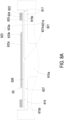
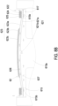
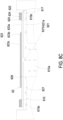
- the volume of the flowing chamber 627 is expanded rapidly, the internal pressure of the flowing chamber 627 is decreased to form a negative pressure, and the gas outside the piezoelectric actuator 62 is inhaled through the clearances 617 and enters the resonance chamber 626 through the hollow aperture 621b. Consequently, the pressure in the resonance chamber 626 is increased to generate a pressure gradient. As shown in FIG.
- the piezoelectric plate 623c is driven to generate the bending deformation in a reciprocating manner.
- the vibration frequency of the gas in the resonance chamber 626 is controlled to be close to the vibration frequency of the piezoelectric plate 623c, so as to generate the Helmholtz resonance effect to achieve the gas transportation at high speed and in large quantities.
- the gas is inhaled from the inlet opening 661a of the outer cover 66, flows into the gas-inlet groove 614 of the base 61 through the gas-inlet 614a, and is transported to the position of the particulate sensor 65.
- the piezoelectric actuator 62 is enabled continuously to inhale the gas into the inlet path, and facilitate the gas outside the gas detection module to be introduced rapidly, flow stably, and transported above the particulate sensor 65.
- a projecting light beam emitted from the laser component 64 passes through the transparent window 614b to irritate the suspended particles contained in the gas flowing above the particulate sensor 65 in the gas-inlet groove 614.
- the scattered light spots are received and calculated by the particulate sensor 65 for obtaining related information about the sizes and the concentration of the suspended particles contained in the gas.
- the gas above the particulate sensor 65 is continuously driven and transported by the piezoelectric actuator 62, flows into the ventilation hole 615a of the gas-guiding-component loading region 615, and is transported to the first section 616b of the gas-outlet groove 616. At last, as shown in FIG.
- the base 61 further includes a light trapping region 618.
- the light trapping region 618 is hollowed out from the first surface 611 to the second surface 612 and spatially corresponds to the laser loading region 613.
- the light trapping region 618 is corresponding to the transparent window 614b so that the light beam emitted by the laser component 64 is projected into the light trapping region 618.
- the light trapping region 618 includes a light trapping structure 618a having an oblique cone surface.
- the light trapping structure 618a spatially corresponds to the light beam path emitted from the laser component 64.
- a light trapping distance D is configured between the transparent window 614b and a position where the light trapping structure 618a receives the projecting light beam.
- the light trapping distance D is greater than 3 mm.
- the projecting light beam projected on the light trapping structure 618a is easy to be reflected back to the position of the particulate sensor 65 directly due to excessive stray light generated after reflection, and it reduces detection accuracy and results in distortion thereof.
- the particle detection module 6 of the present disclosure is not only utilized in detection of the suspended particles in the gas, but also further utilized in detection of the characteristics of the introduced gas.
- the gas could be detected is at least one selected from the group consisting of formaldehyde, ammonia, carbon monoxide, carbon dioxide, oxygen, ozone and a combination thereof.
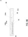
- the particle detection module 6 further includes a volatile-organic-compound sensor 67 positioned and disposed on the driving circuit board 63, electrically connected to the driving circuit board 63, and accommodated in the gas-outlet groove 616, so as to detect the gas flowing through the outlet path of the gas-outlet groove 616.
- the concentration or the characteristics of volatile organic compounds contained in the gas in the outlet path is detected.
- the volatile-organic-compound sensor 67 is accommodated in the light trapping region 618.
- the concentration or the characteristics of volatile organic compounds contained in the gas flowing through the inlet path of the gas-inlet groove 614 and transporting into the light trapping region 618 through the transparent window 614b could be detected.
- the present disclosure provides a gas detection device, wherein the particle detection module starts detecting the suspended particles (e.g., PM1, PM2.5, or PM10) in the gas, and the temperature and humidity sensor starts detecting the temperature and humidity in the environment.
- the detected data information of the suspended particles and the temperature and humidity can be transmitted to the control processing board to convert into the communication information, and outputs the communication information to a cloud processing device through the IOT by the networking module.
- the detected data information can not only be transmitted as warnings or notifications on the indoor display device, but also on the mobile device application (APP).
- the detected data information can be compared through intelligent comparison and big data comparison of the cloud processing device.
- the cloud processing device sends communication commands to the indoor gas cleaning and exchange filtering devices (such as purifiers, exhaust fans, range hoods, fresh air fans, etc.), so as to effectively remove the indoor air pollution.
- the gas detection device is constructed for detecting gas in an indoor air pollution prevention system, and instantly transmits the air quality information to the system, so as to achieve a clean and safe breathing gas state.
- the present disclosure includes the industrial applicability and the inventive steps.
Landscapes
- Chemical & Material Sciences (AREA)
- Health & Medical Sciences (AREA)
- Life Sciences & Earth Sciences (AREA)
- Physics & Mathematics (AREA)
- General Physics & Mathematics (AREA)
- Immunology (AREA)
- Pathology (AREA)
- Analytical Chemistry (AREA)
- Biochemistry (AREA)
- General Health & Medical Sciences (AREA)
- Engineering & Computer Science (AREA)
- Dispersion Chemistry (AREA)
- Food Science & Technology (AREA)
- Medicinal Chemistry (AREA)
- Combustion & Propulsion (AREA)
- Biomedical Technology (AREA)
- Molecular Biology (AREA)
- Mechanical Engineering (AREA)
- General Engineering & Computer Science (AREA)
- Investigating Or Analysing Materials By Optical Means (AREA)
Applications Claiming Priority (1)
| Application Number | Priority Date | Filing Date | Title |
|---|---|---|---|
| TW112123174A TWI881369B (zh) | 2023-06-20 | 2023-06-20 | 氣體偵測裝置 |
Publications (1)
| Publication Number | Publication Date |
|---|---|
| EP4481365A1 true EP4481365A1 (fr) | 2024-12-25 |
Family
ID=90735085
Family Applications (1)
| Application Number | Title | Priority Date | Filing Date |
|---|---|---|---|
| EP24170480.8A Pending EP4481365A1 (fr) | 2023-06-20 | 2024-04-16 | Dispositif de détection de gaz |
Country Status (5)
| Country | Link |
|---|---|
| US (1) | US20240426731A1 (fr) |
| EP (1) | EP4481365A1 (fr) |
| JP (1) | JP7806118B2 (fr) |
| CN (1) | CN119164848A (fr) |
| TW (1) | TWI881369B (fr) |
Citations (2)
| Publication number | Priority date | Publication date | Assignee | Title |
|---|---|---|---|---|
| US20200173971A1 (en) * | 2018-11-29 | 2020-06-04 | Microjet Technology Co., Ltd. | Method of air quality notification |
| US20210172850A1 (en) * | 2019-12-06 | 2021-06-10 | Microjet Technology Co., Ltd. | External gas detecting device |
Family Cites Families (19)
| Publication number | Priority date | Publication date | Assignee | Title |
|---|---|---|---|---|
| JPS6222056A (ja) * | 1985-07-22 | 1987-01-30 | Fujikura Ltd | 空気汚染チエツカ− |
| JP2539466Y2 (ja) * | 1992-04-24 | 1997-06-25 | 矢崎総業株式会社 | プラグ型ガス警報器 |
| JPH08220042A (ja) * | 1995-02-13 | 1996-08-30 | Ishikawajima Harima Heavy Ind Co Ltd | においモニタ |
| JP2001006811A (ja) | 1999-06-22 | 2001-01-12 | Nec Corp | Acコード固定装置 |
| JP4159092B2 (ja) | 2003-09-18 | 2008-10-01 | 富士通テレコムネットワークス株式会社 | ケーブル抜け止め器具 |
| JP5696986B2 (ja) | 2009-07-03 | 2015-04-08 | 大槻 公孝 | Acコード脱落防止具 |
| JP2011249266A (ja) | 2010-05-31 | 2011-12-08 | Fujitsu Telecom Networks Ltd | 電源ケーブルの脱落防止構造 |
| JP2013130540A (ja) | 2011-12-22 | 2013-07-04 | New Cosmos Electric Corp | ガス検知器 |
| CN106969791A (zh) * | 2017-01-18 | 2017-07-21 | 上海依瓦达环境技术有限公司 | 以智能手机作为载体的空气质量监测仪及空气质量监测系统 |
| US10837891B2 (en) * | 2017-12-11 | 2020-11-17 | Honeywell International Inc. | Miniature optical particulate matter sensor module |
| US10620106B2 (en) * | 2017-12-15 | 2020-04-14 | Microjet Technology Co., Ltd. | Particulate matter measuring device |
| TWI710758B (zh) | 2018-04-27 | 2020-11-21 | 研能科技股份有限公司 | 氣體偵測裝置 |
| TWI748327B (zh) * | 2019-09-27 | 2021-12-01 | 研能科技股份有限公司 | 氣體偵測模組 |
| US11704947B2 (en) * | 2019-12-23 | 2023-07-18 | Robert Bosch Gmbh | In-vehicle sensing module for monitoring a vehicle |
| CN211476176U (zh) * | 2020-01-17 | 2020-09-11 | 深圳信息职业技术学院 | 一种小型空气净化器 |
| JP7552437B2 (ja) | 2020-04-07 | 2024-09-18 | 株式会社アイシン | ガス検出装置 |
| US11988591B2 (en) * | 2020-07-01 | 2024-05-21 | Particles Plus, Inc. | Modular optical particle counter sensor and apparatus |
| EP4256322B1 (fr) * | 2020-12-01 | 2025-10-01 | Signify Holding B.V. | Système de détection de la qualité de l'air modulaire |
| TWI832105B (zh) * | 2021-10-13 | 2024-02-11 | 宏致電子股份有限公司 | 具機殼板面定位之連接器總成及其插頭連接器 |
-
2023
- 2023-06-20 TW TW112123174A patent/TWI881369B/zh active
-
2024
- 2024-01-08 CN CN202410026353.2A patent/CN119164848A/zh active Pending
- 2024-03-22 US US18/613,928 patent/US20240426731A1/en active Pending
- 2024-04-12 JP JP2024065008A patent/JP7806118B2/ja active Active
- 2024-04-16 EP EP24170480.8A patent/EP4481365A1/fr active Pending
Patent Citations (2)
| Publication number | Priority date | Publication date | Assignee | Title |
|---|---|---|---|---|
| US20200173971A1 (en) * | 2018-11-29 | 2020-06-04 | Microjet Technology Co., Ltd. | Method of air quality notification |
| US20210172850A1 (en) * | 2019-12-06 | 2021-06-10 | Microjet Technology Co., Ltd. | External gas detecting device |
Also Published As
| Publication number | Publication date |
|---|---|
| JP2025001636A (ja) | 2025-01-08 |
| TW202500973A (zh) | 2025-01-01 |
| US20240426731A1 (en) | 2024-12-26 |
| CN119164848A (zh) | 2024-12-20 |
| JP7806118B2 (ja) | 2026-01-26 |
| TWI881369B (zh) | 2025-04-21 |
Similar Documents
| Publication | Publication Date | Title |
|---|---|---|
| US10935529B2 (en) | Portable device including a gas detecting module for monitoring environmental air conditions | |
| US11772029B2 (en) | Gas detection and purification device | |
| US12485376B2 (en) | Exhaust fan for preventing air pollution | |
| US10969322B2 (en) | Gas detecting device | |
| US10962514B2 (en) | Actuating and sensing apparatus and casing using the same | |
| US10698451B2 (en) | Portable electronic device with actuating and sensing module | |
| US11772030B2 (en) | Miniature gas detection and purification device | |
| US20210109004A1 (en) | Gas-detectable casing of portable device | |
| TWM567361U (zh) | Gas detection device | |
| US11543397B2 (en) | Air detection system | |
| US20240426731A1 (en) | Gas detection device | |
| US12607542B2 (en) | Device for detecting gas and controlling volume of clean gas | |
| US11986763B2 (en) | Remote control system for gas detection and purification | |
| CN113075096B (zh) | 气体检测及净化遥控系统 | |
| US11686715B2 (en) | Mobile power device capable of detecting gas | |
| US11733143B2 (en) | External gas detecting device | |
| US20220305423A1 (en) | Air purification device | |
| US11885785B2 (en) | Health monitoring device having gas detection function | |
| US11945282B2 (en) | Gas detection and cleaning system for vehicle | |
| US20250164137A1 (en) | Indoor air cleaning system with disconnection detecting and preventing mechanism | |
| US20250172474A1 (en) | Detection accuracy enhancing structure of particle detecting module | |
| US20250237591A1 (en) | Particle detecting module | |
| CN113212118B (zh) | 车用气体检测清净系统 | |
| CA3275747A1 (en) | Range hood |
Legal Events
| Date | Code | Title | Description |
|---|---|---|---|
| PUAI | Public reference made under article 153(3) epc to a published international application that has entered the european phase |
Free format text: ORIGINAL CODE: 0009012 |
|
| STAA | Information on the status of an ep patent application or granted ep patent |
Free format text: STATUS: THE APPLICATION HAS BEEN PUBLISHED |
|
| AK | Designated contracting states |
Kind code of ref document: A1 Designated state(s): AL AT BE BG CH CY CZ DE DK EE ES FI FR GB GR HR HU IE IS IT LI LT LU LV MC ME MK MT NL NO PL PT RO RS SE SI SK SM TR |
|
| STAA | Information on the status of an ep patent application or granted ep patent |
Free format text: STATUS: REQUEST FOR EXAMINATION WAS MADE |
|
| 17P | Request for examination filed |
Effective date: 20250623 |