EP4481380A1 - Bildgebungselement, bildgebungsvorrichtung, bildgebungssystem, analyseverfahren und herstellungsverfahren dafür - Google Patents
Bildgebungselement, bildgebungsvorrichtung, bildgebungssystem, analyseverfahren und herstellungsverfahren dafür Download PDFInfo
- Publication number
- EP4481380A1 EP4481380A1 EP24183309.4A EP24183309A EP4481380A1 EP 4481380 A1 EP4481380 A1 EP 4481380A1 EP 24183309 A EP24183309 A EP 24183309A EP 4481380 A1 EP4481380 A1 EP 4481380A1
- Authority
- EP
- European Patent Office
- Prior art keywords
- electrode
- sample
- imaging
- transparent
- imaging device
- Prior art date
- Legal status (The legal status is an assumption and is not a legal conclusion. Google has not performed a legal analysis and makes no representation as to the accuracy of the status listed.)
- Pending
Links
Images


Classifications
-
- G—PHYSICS
- G01—MEASURING; TESTING
- G01N—INVESTIGATING OR ANALYSING MATERIALS BY DETERMINING THEIR CHEMICAL OR PHYSICAL PROPERTIES
- G01N21/00—Investigating or analysing materials by the use of optical means, i.e. using sub-millimetre waves, infrared, visible or ultraviolet light
- G01N21/01—Arrangements or apparatus for facilitating the optical investigation
-
- G—PHYSICS
- G01—MEASURING; TESTING
- G01N—INVESTIGATING OR ANALYSING MATERIALS BY DETERMINING THEIR CHEMICAL OR PHYSICAL PROPERTIES
- G01N21/00—Investigating or analysing materials by the use of optical means, i.e. using sub-millimetre waves, infrared, visible or ultraviolet light
- G01N21/17—Systems in which incident light is modified in accordance with the properties of the material investigated
- G01N21/1717—Systems in which incident light is modified in accordance with the properties of the material investigated with a modulation of one or more physical properties of the sample during the optical investigation, e.g. electro-reflectance
-
- G—PHYSICS
- G01—MEASURING; TESTING
- G01N—INVESTIGATING OR ANALYSING MATERIALS BY DETERMINING THEIR CHEMICAL OR PHYSICAL PROPERTIES
- G01N27/00—Investigating or analysing materials by the use of electric, electrochemical, or magnetic means
- G01N27/60—Investigating or analysing materials by the use of electric, electrochemical, or magnetic means by investigating electrostatic variables, e.g. electrographic flaw testing
-
- G—PHYSICS
- G01—MEASURING; TESTING
- G01N—INVESTIGATING OR ANALYSING MATERIALS BY DETERMINING THEIR CHEMICAL OR PHYSICAL PROPERTIES
- G01N21/00—Investigating or analysing materials by the use of optical means, i.e. using sub-millimetre waves, infrared, visible or ultraviolet light
- G01N21/17—Systems in which incident light is modified in accordance with the properties of the material investigated
- G01N21/1717—Systems in which incident light is modified in accordance with the properties of the material investigated with a modulation of one or more physical properties of the sample during the optical investigation, e.g. electro-reflectance
- G01N2021/1721—Electromodulation
-
- G—PHYSICS
- G01—MEASURING; TESTING
- G01N—INVESTIGATING OR ANALYSING MATERIALS BY DETERMINING THEIR CHEMICAL OR PHYSICAL PROPERTIES
- G01N21/00—Investigating or analysing materials by the use of optical means, i.e. using sub-millimetre waves, infrared, visible or ultraviolet light
- G01N21/17—Systems in which incident light is modified in accordance with the properties of the material investigated
- G01N2021/1765—Method using an image detector and processing of image signal
-
- G—PHYSICS
- G01—MEASURING; TESTING
- G01N—INVESTIGATING OR ANALYSING MATERIALS BY DETERMINING THEIR CHEMICAL OR PHYSICAL PROPERTIES
- G01N2201/00—Features of devices classified in G01N21/00
- G01N2201/06—Illumination; Optics
- G01N2201/062—LED's
- G01N2201/0628—Organic LED [OLED]
-
- G—PHYSICS
- G01—MEASURING; TESTING
- G01N—INVESTIGATING OR ANALYSING MATERIALS BY DETERMINING THEIR CHEMICAL OR PHYSICAL PROPERTIES
- G01N33/00—Investigating or analysing materials by specific methods not covered by groups G01N1/00 - G01N31/00
- G01N33/48—Biological material, e.g. blood, urine; Haemocytometers
- G01N33/483—Physical analysis of biological material
- G01N33/4833—Physical analysis of biological material of solid biological material, e.g. tissue samples, cell cultures
- G01N33/4836—Physical analysis of biological material of solid biological material, e.g. tissue samples, cell cultures using multielectrode arrays
Definitions
- the technical field of the invention is related to the analysis of a sample, for example a biological sample, by an imaging system.
- the invention relates to an imaging element for analyzing a sample, as well as to an imaging device and an imaging system associated therewith.
- the invention further relates to a method for analyzing the sample using the imaging device and to a method for manufacturing the imaging device.
- Organs-on-a-chip are miniaturized cell culture platforms that can reproduce the function and structure of human organs on a micrometric scale and as close as possible to their operation in the human body.
- Organs-on-chips have the advantage of being ideally suited to the integration of sensors, because they are manufactured using similar manufacturing technologies.
- These sensors are essential for accessing information about cells, their interactions, their proliferation or even their response to various stimuli, for example chemical (or medicinal) stimuli, and thus making it possible to understand the functioning of organs and to test the effect of drugs.
- Organs on chips applied to cellular models imitating the central nervous system thus offer the possibility of better understanding the functioning of the brain as well as certain neurodegenerative diseases of the brain, such as Parkinson's disease or Alzheimer's disease, which are linked to functional aberrations of neuronal networks.
- These organs on chips also make it possible to test in vitro the effect of targeted treatments on these diseases.
- electrophysiological sensors For this type of organs-on-chips, electrophysiological sensors have been developed to image the extracellular electrical activity of neurons in real time.
- an action potential This extracellular activity is triggered by a time course of a neuron's intracellular voltage, called an action potential, and is associated with ionic currents across the cell membrane.
- an action potential typically, an action potential lasts between 1 and 2 milliseconds, and during this time the inner membrane potential changes from -70mV to +30mV and then back to -70mV.
- a known type of electrophysiological sensor that combines imaging at the level of a neuron (micrometer scale) and at the level of a neural network (macroscopic scale) uses an array of transistors in a configuration called EOS (acronym for "Electrolyte Oxide Silicon").
- the neurons are in an electrolyte bath which is brought, via an electrode, to a reference potential.
- the transistors do not have a metal gate electrode.
- MTA Multi-Transistor-array
- CMOS complementary metal oxide silicon
- TiO 2 titanium dioxide
- the recording principle is as follows: when a neuronal cell, adhering to the TiO 2 layer opposite a transistor, emits an action potential, it produces at the junction between the cell and the TiO 2 layer an extracellular potential which differs from the reference potential of the electrolyte bath. This local change in the electric field is capacitively coupled, through the insulating TiO 2 layer, to the transistor gate and gives rise to a modulation of the source-drain current calibrated according to the field potential.
- this recording is very sensitive to the position of the neuronal cells on the transistors. It is not enough for a neuronal cell to be positioned opposite a transistor for it to generate a signal there.
- the element that is in contact with the sample and provides a signal in response to an event generated by the sample is called a "receiver”
- the element that receives a signal in one form and transforms it into a signal in another form is called a "transducer”.
- the inventors have identified that an obstacle to addressing the above-mentioned problem is related to the fact that, in the state-of-the-art sensor, the receiver and the transducer are integrated into each other. This implies that the surface of the sensitive area cannot be enlarged in order to decrease the positioning sensitivity and improve the contact robustness without modifying the architecture of the transistor itself.
- the invention provides a solution to the problem mentioned above by making it possible to produce an imaging element in which the receiver and the transducer are two separate elements electrically connected, so that it is possible to easily obtain, that is to say independently of the transducer, a sensitive surface of larger size than the surface of the state-of-the-art CMOS transistor.
- the electroluminescent element can here be understood as an element that produces monochromatic or polychromatic radiation, for example in the spectral band 400-800 nm, by conversion of electrical energy when an electric current passes through it.
- Light-emitting diodes or LEDs (acronym for "Light Emitting Diode” in English) and their derivatives, mainly organic light-emitting diodes or OLEDs (acronym for "Organic Light Emitting Diode” in English) are examples of electroluminescent elements.
- the imaging element comprises a receiver (the electrode) and a transducer (the electroluminescent element) which are two distinct elements separated by the protective layer, located opposite each other, and connected by an electrical connection (via the current source).
- This configuration of the imaging element provides freedom of arrangement of the electrode relative to the electroluminescent element, and makes it possible to adapt the surface of the receiver, and, in any case, to increase it relative to the surface of a CMOS transistor of an MTA matrix, without modifying the transducer (here the electroluminescent element).
- the device according to the first aspect of the invention may also have one or more of the following characteristics, considered individually or in all technically possible combinations.
- the electroluminescent element is disposed between the protective layer and a transparent, semi-transparent support substrate.
- the electrode and the protective layer are transparent or semi-transparent.
- transparent means having an optical transmission coefficient greater than 60% for at least one wavelength in the 400-800nm spectral band.
- semi-transparent means having an optical transmission coefficient greater than 60% for at least one wavelength in the 400-800nm spectral band.
- the light wave propagates through the transparent or semi-transparent electrode, opposite which it can be visualized and/or measured, for example by an optical photodetector.
- the transistor is advantageously a simple technology allowing a difference in potentials to be converted into a current.
- the transistor is a thin film transistor also called a TFT.
- Thin film transistor has several advantages, including good compatibility with microelectronic manufacturing processes, low cost and high flexibility, which enables them to drive different types of light-emitting elements.
- the lateral dimensions of the electrode are greater than the lateral dimensions of the transistor.
- the sensitive surface is increased compared to the state of the art, which allows better detection efficiency (fewer events are “missed” and the response provided by the imaging element more faithfully reflects reality).
- the size of the sensitive surface corresponds to the size of a neuronal cell.
- the imaging element is then well adapted, in size, to detect and follow the extracellular electrical activity of an individual neuronal cell.
- the light-emitting element may be an organic light-emitting diode.
- Organic light-emitting diodes have a relatively simple structure based on a superposition of several organic semiconductor layers between two electrodes, at least one of which is transparent or semi-transparent.
- the manufacturing process is advantageous in terms of cost and complexity, since the semiconductor layers and the electrode can be deposited full wafer (i.e. on the entire surface of the substrate), which avoids lithography and etching steps.
- Organic light-emitting diodes also have the advantage of being available in micrometric lateral dimensions (e.g. 10 ⁇ m and less), of being flexible and easily connectable to an electronic control circuit, for example an electronic circuit in CMOS technology. Finally, they require a lower current than inorganic light-emitting diodes.
- the light emitting element may be an inorganic light emitting diode, preferably a micro inorganic light emitting diode.
- micro-light-emitting diodes or microLEDs have the advantage of having micrometric dimensions well adapted to the size of neuronal cells, for example dimensions between 15 ⁇ m and 20 ⁇ m.
- microLEDs Compared to OLEDs, microLEDs have higher luminance and longer lifetime, but they require higher drive current and are more difficult to manufacture.
- the imaging element further comprises an electronic drive circuit configured to generate a control voltage for the current source, said electronic drive circuit electrically connecting the control electrode of the current source and the electrode.
- a second aspect of the invention relates to an imaging device comprising a plurality of imaging elements according to the first aspect of the invention.
- the imaging elements are preferably arranged to have a first repeat pitch in a first direction and a second repeat pitch in a second direction intersecting the first direction.
- the first repeat pitch is between 4 ⁇ m and 30 ⁇ m and preferably equal to 10 ⁇ m, and the second repeat pitch has the same dimensional characteristics as the first repeat pitch.
- the repetition step is equal to or less than the size of a neuronal cell.
- the device combines imaging capability at multiple scales: the scale of an imaging element, and the scale of the matrix.
- the imaging elements are preferably distributed over an area greater than 1 cm 2 , for example 4 cm 2 .
- Such capabilities make it possible to simultaneously image the activity of a large number of neuronal cells and to study the correlation between this activity and the function of neural networks. It is also possible to multiplex experimental conditions on the same sample. This avoids introducing inter-sample variations that could bias the measurements. Several drugs can thus be tested and their effects compared reliably, with a view to better predicting the effectiveness of future disease treatments.
- This optical system can also be used to image morphological details as well as movements of this sample.
- the generated light wave can be collected by an image sensor, arranged opposite the imaging device, and in which the collection step is followed by a step of acquisition, by the photodetector, of an image representative of the light wave.
- the step of acquiring the image representative of the light wave can be followed by a step of determining the voltage coming from the sample from the image acquired by the image sensor.
- the conductive via and transparent or semi-transparent electrode are formed from the same material, respectively conductive and transparent or conductive and semi-transparent.
- the present invention relates in particular to an imaging device comprising a plurality of imaging elements for detecting and visualizing the electrical activity of a sample.
- the sample will be considered to be a biological sample such as neuronal cells cultured in a culture medium.
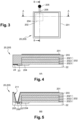
- FIG. 1 A preferred embodiment of this imaging device is shown in the Figures 1 and 2 , respectively according to a top view and according to a sectional view.
- the imaging device 1 comprises mx n imaging elements 20.
- m and n are non-zero positive natural integers.
- m and n may be equal to 2000.
- the imaging elements 20 are of the same type, i.e. manufactured together and in the same manner, and therefore have the same or very similar characteristics. They are preferably identical.
- the imaging elements 20 are arranged in rows and columns in the form of a matrix 2. They advantageously have a first repetition pitch P1 in a first direction D1 and a second repetition pitch P2 in a second direction D2 intersecting the first direction.
- the second direction D2 is for example perpendicular to the first direction D1.
- the repetition steps P1, P2 can be identical.
- the imaging device then comprises a regular network, or matrix, of imaging elements.
- the repetition steps P1, P2 are between 4 ⁇ m and 30 ⁇ m.
- the repeat steps P1, P2 are between 4 ⁇ m and 10 ⁇ m.
- the repeat steps P1, P2 are equal to or less than the size of a neuronal cell.
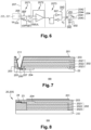
- the general principle of operation of the imaging device 1 is described in relation to the figure 2 .
- Device 1 is intended to receive the sample E CH .
- one of the neuronal cells Cs of this sample E CH emits an action potential, it produces an extracellular potential Vin 20S on the surface of the imaging element 20S with which it is in contact which, in response, produces locally, on the surface of the device 1, a light wave O 20S having at least a length wave, for example in the spectral band 400 nm - 800 nm, and whose intensity depends on the amplitude of the extracellular potential Vin 20S .
- the other imaging elements 20 are inactive or “off.”
- the light wave O 20S is localized at the level of the electrically active cell, and the intensity of this light wave varies according to the extracellular potential Vin 20S , it is possible to acquire a quantitative mapping of the electrical activity of the sample E CH .
- the imaging elements 20 are thus comparable to pixels of a screen, with the difference that the signal O 20S that they deliver is controlled by, or a function of, the electrical activity Vin 20S of the sample Ech.
- FIG. 3 to 6 schematically represent, according to different views, a first embodiment of the imaging element 20.
- Electrode 201 is used as a sensitive surface, or receiver, that is to say it is in contact with the sample E CH , more precisely with a cell Cs of this sample E CH , and collects the extracellular potential Vin 20S emitted by this cell Cs in contact.
- suitable for receiving the E CH sample means that the electrode is not such as to degrade this E CH sample when it is in contact with it.
- the electrode 201 is biocompatible.
- the electrode 201 has lateral dimensions preferably between 4 ⁇ m and 20 ⁇ m, and for example equal to 10 ⁇ m.
- neuronal cells which is generally between 10 ⁇ m or 15 ⁇ m. More precisely, these dimensions are small enough to allow the analysis of an individual neuronal cell, and large enough for the connection with this individual cell to be robust with respect to the position of this cell.
- the sensitive surface thus obtained is in fact notably larger than that previously described in the state of the art, which makes it possible to improve the capacity for detecting an action potential (or, in other words, the risk of missing an electrical event is reduced).
- the entire surface of the electrode 201 is conductive, the position of the neuronal cell on the electrode 201 is of little importance. In other words, there is no need for the sample to be precisely positioned on a certain portion of the imaging element for an action potential to be detected.
- the imaging element is thus well suited for electrical imaging of an individual neuronal cell, while being, compared to the state of the art, less sensitive to the position of the sample, which increases the detection efficiency and makes it possible to obtain a more faithful response (more consistent) with the actual electrical activity of the sample.
- the electroluminescent element 202 is used as an electro-optical transducer, making it possible to produce, as previously described in relation to the figure 2 , the light wave O 20S in response to the extracellular potential Vin 20S generated by the sample E CH and collected by the electrode 201.
- the electroluminescent element 202 designates an element which produces monochromatic or polychromatic non-coherent radiation in the 400-800 nm spectral band, i.e. in the transparency spectral band, by conversion of electrical energy when an electric current passes through it.
- the intensity of this radiation is advantageously proportional to the electric current.
- the light-emitting element 202 is an organic light-emitting diode or OLED (acronym for “Organic Light Emitting Diode”).
- OLED organic Light Emitting Diode
- This is a technology that allows for easier and less expensive manufacturing and integration, and for driving the device with lower control currents than an LED (acronym for “Light Emitting Diode”) for example.
- the internal structure of the electroluminescent element 202 is shown in particular in figure 4 and in figure 5 (for the first embodiment), and in Figures 8 And 9 (for the second embodiment).
- the electroluminescent element 202 comprises an organic layer 2022 disposed between two electrodes, the anode 2023 and the cathode 2021 which are transparent or semi-transparent.
- the electroluminescent element 202 has lateral dimensions which are preferably close to the lateral dimensions of the transparent electrode 201. Thus, these dimensions are preferably between 10 ⁇ m and 15 ⁇ m, for example 12 ⁇ m.
- Such dimensions make it possible to obtain a good spatial correspondence between the transparent electrode 201 (the receiver) and the electroluminescent element 202 (the transducer).
- the cathode 2021, the organic layer 2022 and the anode 2023 of the electroluminescent element 202 are structured to have the desired lateral dimensions.
- the organic layer 2022 can be formed of several layers, for example an HTL layer (acronym for “Hole Transporting Layer” in English) and an emissive layer.
- HTL layer an HTL layer (acronym for “Hole Transporting Layer” in English)
- emissive layer an HTL layer (acronym for “Hole Transporting Layer” in English)
- the anode 2023 of the electroluminescent element 202 is structured to have these dimensions. From a manufacturing point of view, this arrangement simplifies the process since the organic layer 2022 and the cathode 2021 can be formed by a single-step deposition, i.e. without a lithography and etching step.
- the electroluminescent element 202 may also be an inorganic light-emitting diode (or LED), in particular a microLED.
- LED inorganic light-emitting diode
- micro-light-emitting diodes or microLEDs have the advantage of having micrometric dimensions well adapted to the size of neuronal cells, for example dimensions between 15 ⁇ m and 20 ⁇ m.
- microLEDs Compared to OLEDs, microLEDs have higher luminance and longer lifetime, but they require higher drive current and are more difficult to manufacture.
- the electrode 201 is distinct from the electroluminescent element 202. In particular, it is distinct from the electrodes, anode 2021 and cathode 2023, of this electroluminescent element 202.
- the protective layer 203 can also surround the electrode 201 when the latter does not cover the entire surface of the imaging element 20. It can also serve to separate the imaging elements 20 from each other in the imaging device 1 shown in figure 2 . It then forms insulating blocks separating the imaging elements 20. In these two cases, the ECH sample can also be in contact with the layer protective electrode 203 which is then, like the electrode 201, adapted to receive the sample E CH .
- Inorganic layers are, for example, based on aluminium oxide (Al2O3) or titanium dioxide (TiO2).
- Organic layers are based on resin.
- the thickness of the protective layer 203 is preferably between 25 nm and 1 ⁇ m, and is for example equal to 300 nm.
- the current source 204 makes it possible to drive the electroluminescent element 202 in response to the electrical activity Vin 20S of the sample E CH .
- the current source 204 has the effect of converting the extracellular potential Vin 20S generated by the sample E CH (and collected by the electrode 201) into a current passing through the electroluminescent element 202 and capable of generating the light wave O 20S in this electroluminescent element 202.
- the electrical connection between the current source 204 and the transparent electrode 201 comprises an electrical track 206, a connection pad 205, and a conductive via 211.
- the electrical track 206 is for example metallic.
- connection pad 205 is for example metallic.
- the conductive via 211 extends from the transparent electrode 201 to the connection pad 205.
- the conductive via 211 is formed of the same material as the transparent electrode 201. The manufacturing process is facilitated because the electrode 201 and the via 211 are formed simultaneously.
- FIG. 6 is an example of a simplified electrical diagram of the imaging element 20, compatible with all embodiments of the imaging element 20.
- this power supply terminal can be coupled, via metallic electrical tracks 23, 24 to a voltage source (not shown in the figure 5 ).
- the transistor 2041 is a thin film transistor also called TFT (acronym for “Thin Film Transistor” in English).
- the transistor 2041 provides a current i D between the drain and source electrodes 2043,2044 which is controlled by the voltage V DD applied to the supply terminal (and therefore to the drain electrode 2044) and by the electrical voltage Vc of the gate electrode 2042.
- the references VSEUIL, VOFFSET, RST and RST correspond to control voltages.
- Transistor 2041 operates in saturated mode.
- the transistor 2041 In the absence of electrical activity of the neuronal cell Cs, the transistor 2041 is blocked. No current I D flows between the drain electrodes 2042 and source electrodes 2043, nor through the electroluminescent element 202. The electroluminescent element 202 is therefore off and forms a “black” pixel.
- the extracellular potential Vin 20S modifies the voltage Vc of the gate electrode, which is then sufficient to turn on the transistor 2041.
- a current i D proportional to the gate voltage Vc then passes through the electroluminescent element 202 which emits the light wave O 20S with an intensity proportional to the gate voltage Vc.
- a calibration phase the electrical potential on the transparent electrode 201 is modulated around an operating point and the intensity variations of the light wave O 20S are measured. Calibration data associated with the imaging element 20, 20S are thus obtained.
- the light intensity is measured and reported, via the calibration data, to the amplitude of the extracellular potential V in20S .
- the imaging element 20 preferably comprises an electronic control circuit 207 electrically connected, on the one hand, to the control electrode 2042 of the current source 204, and on the other hand, via the connection pad 205, to the transparent electrode 201.
- the driving circuit 207 is configured to generate, from the extracellular potential Vi n20S , an electrical control voltage Vc on the control electrode 2042 of the current source 204.
- control circuit 207 can comprise one or more functional blocks called stages, arranged in series.
- the transparent electrode 201 includes a switch stage 2071 for triggering the reading of the transparent electrode 201, and in doing so, providing an extracellular voltage V ex from the extracellular potential Vin 20S and a reference voltage Voffset.
- This duration is, at most, the same as the time of the neuronal activity, i.e. from 1 ms to 2 ms.
- this duration is adapted to guarantee an observation time (of the light wave) sufficient to be measurable, for example this duration is between 10 ⁇ s and 100 ⁇ s.
- Stage 2071, amplification stage 2072 and memory stage 2073 arranged, in order, in series.
- the electrode 201 is transparent, or semi-transparent, as is the protective layer 203.
- semi-transparent is used for any material or element which has an optical transmission coefficient greater than 60% for at least one wavelength included in the spectral band extending into the visible range, i.e. between 400 nm and 800 nm.
- transparent is used for any material or element which has an optical transmission coefficient greater than 80% for at least one wavelength included in the spectral band extending into the visible range, i.e. between 400 nm and 800 nm.
- the light wave O 20S generated by the electroluminescent element 202 in response to the electrical activity of the sample E CH passes through the transparent or semi-transparent protective layer 203 and the transparent or semi-transparent electrode 201.
- the light wave O 20S is therefore generated at least partly on the same side as the sample E CH .
- the transparent or semi-transparent electrode 201 is formed from a transparent, or respectively semi-transparent, and conductive material.
- this material is chosen from the following materials: Poly(3,4-ethylenedioxythiophene) (or PEDOT), indium-tin oxide (or ITO for “Indium Tin Oxide” in English), tin dioxide (SnO 2 ), zinc oxide (ZnO) or aluminum-doped zinc oxide (or AZO).
- the transparent or semi-transparent electrode 201 can also be formed from a thin layer, between 5 nm and 100 nm, of aluminum (Al), silver (Ag), or chromium (Cr).
- the electrode 201 is transparent when it has a thickness between 5 nm and 30 nm.
- the electrode 201 is semi-transparent when it has a thickness between 5 nm and 100 nm.
- the anode 2023 of the electroluminescent element is an optical reflection surface.
- the light wave O 20S is generated essentially in the direction of the transparent or semi-transparent electrode 201. This configuration avoids optical losses, and makes it possible to improve the sensitivity limit of the imaging element 20.
- the voltage-controlled current source 204 is part of an electronic circuit 22.
- This circuit 22 is for example coupled to the electroluminescent element 202 on the side of the anode 2023 of this electroluminescent element 202.
- the electronic circuit 22 also serves as a substrate, or support for the imaging element 20, and more broadly for the imaging device 1 illustrated in figure 1 .
- the electrical track 206 is preferably integrated into the electronic circuit 22.
- connection pad 205 is preferably integrated into the electronic circuit 22. It is for example arranged so as to be flush with the surface of the circuit 22. It can also be arranged as a projection (not shown in the figure). figure 6 ).
- the light wave O 20S generated by the electroluminescent element 202 in response to the electrical activity of the sample E CH passes through this transparent or semi-transparent substrate 200.
- the transparent or semi-transparent substrate 200 serves as protection and support for the electroluminescent element 202. It may be glass.
- the electrode 201 and the protective layer 203 are not necessarily transparent or semi-transparent.
- the electrode 201 may be formed of a metal, for example aluminum (Al), silver (Ag) or chromium (Cr).
- the electrode 201 is a reflection surface.
- the metal used to form this electrode 201 can then be silber (Ag). This makes it possible to optimize the optical power passing through the substrate 200, and therefore to improve the detection limit of the imaging element 20.
- the 2021 cathode of the electroluminescent element can also be a reflective surface.
- connection of the current source 204 to the metal tracks 23 and 24 is, similarly, arranged so as not to block the passage of the light wave O 20S through the substrate 200.
- the current source 204, as well as the connection elements 205, 206, 211 and the electronic circuit 207 are arranged so that they do not block the passage of the light wave O 20S through the substrate 200.
- they can be arranged, at least in part, between the electrode 201 and the electroluminescent element 202.
- the arrangement in superimposed levels of the current source 204, of the element electroluminescent layer 202, protective layer 203 and transparent electrode 201 makes it possible to obtain a compact imaging element 20, integrating all the reception/transduction functions.
- the matrix 2 of imaging elements 20 with a high density, for example more than 6000 electrodes per mm 2 , and large surface area, for example 2x2 cm 2 .
- the imaging device 1 thus has imaging capabilities combining a micrometric spatial resolution, between 4 ⁇ m and 10 ⁇ m, and a centimetric analysis field, for example 4 cm 2 , superior to the state of the art.
- Such capabilities make it possible to simultaneously image the activity of a large number of neuronal cells and to study the correlation between this activity and the function of neural networks. It is also possible to multiplex experimental conditions on the same sample. This avoids introducing inter-sample variations that could bias the measurements. Several drugs can thus be tested and their effects compared reliably, with a view to better predicting the effectiveness of future disease treatments.
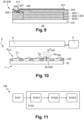
- Another aspect of the invention relates to an imaging system 3, shown in figure 3 , using imaging device 1.
- This system 3 makes it possible to acquire an image of the light wave O 20S generated by the imaging device 1 under the effect of the sample E CH , then to carry out, from this image, an optical detection of the electrical activity of the sample E CH .
- the imaging system 3 comprises for this purpose the imaging device 1, an image sensor 4, and a processor 5.
- the image sensor 4 is formed of a matrix of pixels and thus adapted to form, and acquire, at least one image of the light wave O 20S generated by the imaging device 1 under the effect of a sample E CH .
- the image sensor 4 is arranged relative to the imaging device 1 so as to collect the light wave O 20S generated by one or more of the imaging elements 20S of the imaging device 1. In other words, it is arranged on the side of the face of the device 1 which is crossed by the light wave O 20S .
- the imaging device 1 integrates the imaging elements 20 according to the first embodiment (in which the electrode 201 and the protective layer 203 are transparent or semi-transparent).
- the photodetector 4 is arranged on the side of the electrodes 201 of these imaging elements 20, and therefore on the side of the sample E CH .
- the photodetector 4 is arranged on the side opposite the electrodes 201 and the sample E CH .
- This image sensor 4 can be coupled with the face of the imaging device crossed by the light wave O 20S by focusing optics, such as optical lenses, objectives, etc.
- the 4 image sensor can be integrated into a microscope.
- the processor 5 communicates with the image sensor 4. It is, for example, a microprocessor. It makes it possible to process the image formed by the image sensor, i.e. to carry out operations for determining characteristics of the image, etc.
- Another aspect of the invention relates to a method of analyzing the E CH sample using the imaging device 1.
- This analysis method 100 is described in relation to the figure 11 . It includes the main steps S101, S102 and S103.
- the analysis method 100 begins with step S101 consisting of depositing the sample E CH on the imaging device 1, in contact with at least one of the electrodes 201 of this imaging device 1.
- Each electrode 201 in contact with the sample belongs to a corresponding imaging element 20 of said imaging device 1, and is associated with the electroluminescent element of said imaging element 20.
- step S102 which consists of carrying out an optical detection of the electrical activity of the sample E CH .
- This optical detection comprises a step S1021 of collecting a light wave O 20S generated by the electroluminescent element (202) of the imaging element corresponding to the contact electrode, this light wave O 20S being formed in response to a voltage Vin 20S coming from the sample E CH .
- Optical detection can be achieved using the image sensor 4 of the imaging system 3 (cf. figure 10 ).
- the collection S1021 of the light wave O 20S is carried out by the image sensor 4.
- the collection step S1021 can then be followed by an acquisition step S1022, by the image sensor 4, of an image representative of the light wave O 20S formed on the image sensor 4.
- This acquisition step S1022 can then continue with a determination step S1023 of the electrical activity of the sample, precisely of the voltage Vin 20S coming from the sample E CH from the image acquired by the image sensor 4.
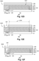
- Another aspect of the invention relates to a method of manufacturing the imaging element 20.
- FIGS 12A to 12L illustrate the steps and sub-steps of this manufacturing method 900 for manufacturing the imaging element 20 according to the first embodiment (illustrated in Figures 3, 4 and 5 ). It will be considered that this first embodiment comprises that the protective layer 203 and the electrode 201 are transparent.
- the method 900 comprises the steps S901, S902, S903, S904, S905, S906, S907, S908, S909, S910, S911 and S912 illustrated respectively in Figure 12A , in Figure 12B , in figure 12C , in figure 12D , in Figure 12E , in Figure 12F , in figure 12G , in figure 12H , in figure 12I , in figure 12J , in figure 12K , and in figure 12L .
- the transparent electrode 201 and the contact connection to the electronic circuit through the via 211 are formed simultaneously by depositing the same transparent and conductive material.
- step S901 which consists of providing the electronic circuit 22.
- This circuit 22 includes the connection pad 205 and the voltage-controlled current source 204.
- the current source 204 includes the control electrode 2042 (not shown in Figure 12A ) electrically connected to the connection pad 205 via the electrical track 206.
- the circuit 22 further comprises the electronic control circuit 207.
- Step S902 illustrated in Figure 12B , is performed after step S901 and consists of forming, on the electronic circuit 22, the electroluminescent element 202.
- Step S903 illustrated in figure 12C , follows step S902 and consists of encapsulating the electroluminescent element 202 by the transparent protective layer 203 (or encapsulation layer).
- This protective layer 203 covers the electroluminescent element 202 and the connection pad 205.
- Steps S904, S905, S906 and S907 following step S903 aim to prepare the formation of the conductive via 211 by forming an opening 210 at a zone adjacent to the zone 2024 (cf. figure 12F ) of the electroluminescent element, this opening 210 extending from the surface 2031 of the protective layer 203 to the connection pad 205.
- Step S904 is a step of depositing a first sacrificial layer 208 on the surface 2031 of the protective layer 203.
- the sacrificial layer 208 is preferably a photosensitive resin layer.
- Step S905, illustrated in Figure 12E is a step of forming a first opening 209 through the first sacrificial layer 208 in the area adjacent to the area 2024, typically by exposure and development of the photosensitive resin.
- the opening 209 opens onto the protective layer 203.
- Step S906, illustrated in figure 12F consists of forming a second opening 210 in the extension of the first opening 209, up to the electronic circuit 22, by vertical etching of the protective layer 203 through the first sacrificial layer 208.
- the first sacrificial layer 208 acts as an etching mask.
- Step S907 illustrated in figure 12G , consists of removing the first sacrificial layer 208.
- Steps S908, S909, S910, S911 and S912 aim to form the transparent electrode 201 and the conductive via 211.
- the transparent electrode 201 and the conductive via 211 are advantageously formed by deposition, photolithography and etching of the same layer of transparent and conductive material 201a.
- Step S908 illustrated in figure 12H follows step S907 and consists of depositing the transparent and conductive material 201a on the entire surface 2031 of the protective layer 203 and in the second opening 210.
- Steps S909, S910, S911 and S912 aim in particular to delimit the transparent electrode 201 so that it has the desired shape and dimensions.
- Step S909 illustrated in figure 12I , consists of depositing a second sacrificial layer 212 (typically a layer of photosensitive resin) on the layer of conductive and transparent material 201a deposited previously.
- a second sacrificial layer 212 typically a layer of photosensitive resin
- Step S910 is a localized removal step of the second sacrificial layer 212 (typically by exposure and development of the photosensitive resin layer). The removal is carried out in a zone 2011 located around the zone of the electroluminescent element 202.
- Step S911, illustrated in figure 12K is a step of etching the transparent and conductive material layer 201a through the second sacrificial layer 212 (the second sacrificial layer 212 acts as an etching mask).
- Step S912, illustrated in figure 12L is a step of removing the remaining portion of the second sacrificial layer 212.
- the conductive and transparent material 201a forms the transparent electrode 201, and on the walls of the second opening 210, it forms the conductive via 211.
- step S912 the imaging element 20 is formed.
- the imaging device 1 can be manufactured according to a manufacturing method derived from the manufacturing method of the imaging element 20 which has just been described.
Landscapes
- Health & Medical Sciences (AREA)
- Life Sciences & Earth Sciences (AREA)
- Chemical & Material Sciences (AREA)
- Physics & Mathematics (AREA)
- Immunology (AREA)
- Pathology (AREA)
- Analytical Chemistry (AREA)
- Biochemistry (AREA)
- General Health & Medical Sciences (AREA)
- General Physics & Mathematics (AREA)
- Engineering & Computer Science (AREA)
- Biomedical Technology (AREA)
- Electrochemistry (AREA)
- Chemical Kinetics & Catalysis (AREA)
- Molecular Biology (AREA)
- Biophysics (AREA)
- Hematology (AREA)
- Optics & Photonics (AREA)
- Urology & Nephrology (AREA)
- Food Science & Technology (AREA)
- Medicinal Chemistry (AREA)
- Investigating, Analyzing Materials By Fluorescence Or Luminescence (AREA)
- Investigating Or Analysing Materials By Optical Means (AREA)
- Electroluminescent Light Sources (AREA)
Applications Claiming Priority (1)
| Application Number | Priority Date | Filing Date | Title |
|---|---|---|---|
| FR2306478A FR3150293B1 (fr) | 2023-06-22 | 2023-06-22 | Élément d’imagerie, dispositif d’imagerie, système d’imagerie, procédé d’analyse et procédé de fabrication associés |
Publications (1)
| Publication Number | Publication Date |
|---|---|
| EP4481380A1 true EP4481380A1 (de) | 2024-12-25 |
Family
ID=89158090
Family Applications (1)
| Application Number | Title | Priority Date | Filing Date |
|---|---|---|---|
| EP24183309.4A Pending EP4481380A1 (de) | 2023-06-22 | 2024-06-20 | Bildgebungselement, bildgebungsvorrichtung, bildgebungssystem, analyseverfahren und herstellungsverfahren dafür |
Country Status (3)
| Country | Link |
|---|---|
| US (1) | US12461017B2 (de) |
| EP (1) | EP4481380A1 (de) |
| FR (1) | FR3150293B1 (de) |
Citations (1)
| Publication number | Priority date | Publication date | Assignee | Title |
|---|---|---|---|---|
| US6501846B1 (en) * | 1997-11-25 | 2002-12-31 | Ethentica, Inc. | Method and system for computer access and cursor control using a relief object image generator |
Family Cites Families (7)
| Publication number | Priority date | Publication date | Assignee | Title |
|---|---|---|---|---|
| US20060007248A1 (en) * | 2004-06-29 | 2006-01-12 | Damoder Reddy | Feedback control system and method for operating a high-performance stabilized active-matrix emissive display |
| JP6479720B2 (ja) * | 2016-08-30 | 2019-03-06 | 株式会社電通 | 瞑想補助装置および瞑想補助システム |
| US10764975B2 (en) * | 2018-03-30 | 2020-09-01 | Facebook Technologies, Llc | Pulse-width-modulation control of micro light emitting diode |
| US11640089B2 (en) * | 2020-08-21 | 2023-05-02 | Sharp Kabushiki Kaisha | Liquid crystal display device and display system |
| FR3127073B1 (fr) * | 2021-09-13 | 2024-01-19 | Commissariat Energie Atomique | Dispositif optoelectronique a composants emissif et photodetecteur superposes |
| EP4261505B1 (de) * | 2022-04-14 | 2024-10-30 | Melexis Technologies NV | Vorrichtung zur messung des reflexionsvermögens und verfahren zur messung des reflexionsvermögens dafür |
| US12490606B2 (en) * | 2022-07-27 | 2025-12-02 | Samsung Display Co., Ltd. | Display device |
-
2023
- 2023-06-22 FR FR2306478A patent/FR3150293B1/fr active Active
-
2024
- 2024-06-20 EP EP24183309.4A patent/EP4481380A1/de active Pending
- 2024-06-24 US US18/751,432 patent/US12461017B2/en active Active
Patent Citations (1)
| Publication number | Priority date | Publication date | Assignee | Title |
|---|---|---|---|---|
| US6501846B1 (en) * | 1997-11-25 | 2002-12-31 | Ethentica, Inc. | Method and system for computer access and cursor control using a relief object image generator |
Non-Patent Citations (3)
| Title |
|---|
| LAMBACHER ET AL.: "Electrical imaging of neuronal activity by multi-transistor-array (MTA) recording at 7,8 µm resolution", APPLIED PHYSICS A., 2004 |
| TAKASHI TOKUDA ET AL: "Optical and Electric Multifunctional CMOS Image Sensors for On-Chip Biosensing Applications", MATERIALS, vol. 4, no. 1, 29 December 2010 (2010-12-29), pages 84 - 102, XP055347233, DOI: 10.3390/ma4010084 * |
| VOELKER ET AL.: "Signal Transmission from individual mammalian nerve cell to field-effect transistor", SMALL JOURNAL, vol. 2, 2005, pages 206 - 210, XP002431370, DOI: 10.1002/smll.200400077 |
Also Published As
| Publication number | Publication date |
|---|---|
| US12461017B2 (en) | 2025-11-04 |
| US20240426742A1 (en) | 2024-12-26 |
| FR3150293A1 (fr) | 2024-12-27 |
| FR3150293B1 (fr) | 2025-06-13 |
Similar Documents
| Publication | Publication Date | Title |
|---|---|---|
| EP0882979B1 (de) | Elektrodentragvorrichtung bestehend aus mindestens einer Elektrode mit Überzug und System zum lesen | |
| EP1378113B1 (de) | Photoempfindliche vorrichtung und verfahren zur steuerung der photoempfindlichen vorrichtung | |
| EP0367650B1 (de) | Photoempfindliche Vorrichtung mit Signalverstärkung im Bereich der photoempfindlichen Punkte | |
| EP0364314B1 (de) | Verfahren zum Lesen von lichtempfindlichen Zellen mit zwei in Reihe angeordneten Dioden und mit entgegenwirkenden Durchlassrichtungen | |
| EP0763751A1 (de) | Verfahren und Vorrichtung zur Korrektur der Signal von Gammaphotonspektroskopie | |
| EP3236841B1 (de) | Bildgebungsvorrichtung und -verfahren | |
| FR3065320A1 (fr) | Pixel de detection de temps de vol | |
| WO1998036579A2 (fr) | Dispositif et procede de traitement de signaux d'un detecteur de rayonnements a semi-conducteurs | |
| EP2378258A1 (de) | Detektor für elektromagnetische Strahlung eine reduzierte Empfindlichkeit gegen räumliches Rauschen aufweisend | |
| EP4149232A1 (de) | Matrixanordnung für bildsensor mit dünnfilmtransistoren und organischen fotodioden | |
| EP2343543A1 (de) | Elektrochemischer und/oder elektrischer Biosensor mit integrierten Diamantenelektrode und elektronischem Schaltkreis | |
| EP4481380A1 (de) | Bildgebungselement, bildgebungsvorrichtung, bildgebungssystem, analyseverfahren und herstellungsverfahren dafür | |
| EP3144704B1 (de) | Vorrichtung zur bilderfassung mit integrierter beleuchtung, und herstellungsverfahren dieser vorrichtung | |
| Xiong et al. | Spectrally filtered passive Si photodiode array for on-chip fluorescence imaging of intracellular calcium dynamics | |
| EP3471151B1 (de) | Helmholtz-resonator-photodetektor | |
| FR2793071A1 (fr) | Gamma camera miniature a detecteurs semiconducteurs | |
| EP0712166A1 (de) | Photodetektor grossen Ausmasses und Verfahren zur Herstellung eines solchen | |
| WO2014096746A1 (fr) | Procede et dispositif de detection de rayonnement ionisant a detecteur semiconducteur | |
| EP4138128B1 (de) | Bilderfassungsvorrichtung | |
| EP1359400B1 (de) | Thermische Strahlungsdetektionsvorrichtung mit beschränkter Anzahl von Befestigungspunkten | |
| FR2855913A1 (fr) | Reseau de condensateurs de stockage pour dispositif d'imagerie a l'etat solide | |
| WO2023002130A1 (fr) | Procede de capture d'image par canaux auxiliaires, a l'aide d'un ecran d'affichage | |
| JP2003101029A (ja) | 薄膜トランジスタ、フォトセンサ及びその製造方法 | |
| WO2014072595A1 (fr) | Surface photovoltaïque polarisante | |
| EP0882980A1 (de) | Oberflächenbehandlung für ein Substrat zur begrenzung der Fluoreszenz |
Legal Events
| Date | Code | Title | Description |
|---|---|---|---|
| PUAI | Public reference made under article 153(3) epc to a published international application that has entered the european phase |
Free format text: ORIGINAL CODE: 0009012 |
|
| STAA | Information on the status of an ep patent application or granted ep patent |
Free format text: STATUS: REQUEST FOR EXAMINATION WAS MADE |
|
| 17P | Request for examination filed |
Effective date: 20240620 |
|
| AK | Designated contracting states |
Kind code of ref document: A1 Designated state(s): AL AT BE BG CH CY CZ DE DK EE ES FI FR GB GR HR HU IE IS IT LI LT LU LV MC ME MK MT NL NO PL PT RO RS SE SI SK SM TR |
|
| GRAP | Despatch of communication of intention to grant a patent |
Free format text: ORIGINAL CODE: EPIDOSNIGR1 |
|
| STAA | Information on the status of an ep patent application or granted ep patent |
Free format text: STATUS: GRANT OF PATENT IS INTENDED |
|
| INTG | Intention to grant announced |
Effective date: 20260217 |