EP4481406A1 - Procédé et circuit électrique pour la surveillance sélective de l'isolation dans un système d'alimentation électrique avec sous-systèmes séparables - Google Patents
Procédé et circuit électrique pour la surveillance sélective de l'isolation dans un système d'alimentation électrique avec sous-systèmes séparables Download PDFInfo
- Publication number
- EP4481406A1 EP4481406A1 EP24183029.8A EP24183029A EP4481406A1 EP 4481406 A1 EP4481406 A1 EP 4481406A1 EP 24183029 A EP24183029 A EP 24183029A EP 4481406 A1 EP4481406 A1 EP 4481406A1
- Authority
- EP
- European Patent Office
- Prior art keywords
- subsystem
- time interval
- insulation
- measuring
- measuring time
- Prior art date
- Legal status (The legal status is an assumption and is not a legal conclusion. Google has not performed a legal analysis and makes no representation as to the accuracy of the status listed.)
- Granted
Links
Images



Classifications
-
- G—PHYSICS
- G01—MEASURING; TESTING
- G01R—MEASURING ELECTRIC VARIABLES; MEASURING MAGNETIC VARIABLES
- G01R31/00—Arrangements for testing electric properties; Arrangements for locating electric faults; Arrangements for electrical testing characterised by what is being tested not provided for elsewhere
- G01R31/50—Testing of electric apparatus, lines, cables or components for short-circuits, continuity, leakage current or incorrect line connections
- G01R31/52—Testing for short-circuits, leakage current or ground faults
-
- G—PHYSICS
- G01—MEASURING; TESTING
- G01R—MEASURING ELECTRIC VARIABLES; MEASURING MAGNETIC VARIABLES
- G01R31/00—Arrangements for testing electric properties; Arrangements for locating electric faults; Arrangements for electrical testing characterised by what is being tested not provided for elsewhere
- G01R31/12—Testing dielectric strength or breakdown voltage ; Testing or monitoring effectiveness or level of insulation, e.g. of a cable or of an apparatus, for example using partial discharge measurements; Electrostatic testing
- G01R31/1227—Testing dielectric strength or breakdown voltage ; Testing or monitoring effectiveness or level of insulation, e.g. of a cable or of an apparatus, for example using partial discharge measurements; Electrostatic testing of components, parts or materials
- G01R31/1263—Testing dielectric strength or breakdown voltage ; Testing or monitoring effectiveness or level of insulation, e.g. of a cable or of an apparatus, for example using partial discharge measurements; Electrostatic testing of components, parts or materials of solid or fluid materials, e.g. insulation films, bulk material; of semiconductors or LV electronic components or parts; of cable, line or wire insulation
- G01R31/1272—Testing dielectric strength or breakdown voltage ; Testing or monitoring effectiveness or level of insulation, e.g. of a cable or of an apparatus, for example using partial discharge measurements; Electrostatic testing of components, parts or materials of solid or fluid materials, e.g. insulation films, bulk material; of semiconductors or LV electronic components or parts; of cable, line or wire insulation of cable, line or wire insulation, e.g. using partial discharge measurements
-
- G—PHYSICS
- G01—MEASURING; TESTING
- G01R—MEASURING ELECTRIC VARIABLES; MEASURING MAGNETIC VARIABLES
- G01R27/00—Arrangements for measuring resistance, reactance, impedance, or electric characteristics derived therefrom
- G01R27/02—Measuring real or complex resistance, reactance, impedance, or other two-pole characteristics derived therefrom, e.g. time constant
- G01R27/025—Measuring very high resistances, e.g. isolation resistances, i.e. megohm-meters
-
- G—PHYSICS
- G01—MEASURING; TESTING
- G01R—MEASURING ELECTRIC VARIABLES; MEASURING MAGNETIC VARIABLES
- G01R27/00—Arrangements for measuring resistance, reactance, impedance, or electric characteristics derived therefrom
- G01R27/02—Measuring real or complex resistance, reactance, impedance, or other two-pole characteristics derived therefrom, e.g. time constant
- G01R27/16—Measuring impedance of element or network through which a current is passing from another source, e.g. cable, power line
- G01R27/18—Measuring resistance to earth, i.e. line to ground
-
- G—PHYSICS
- G01—MEASURING; TESTING
- G01R—MEASURING ELECTRIC VARIABLES; MEASURING MAGNETIC VARIABLES
- G01R31/00—Arrangements for testing electric properties; Arrangements for locating electric faults; Arrangements for electrical testing characterised by what is being tested not provided for elsewhere
- G01R31/08—Locating faults in cables, transmission lines, or networks
-
- G—PHYSICS
- G01—MEASURING; TESTING
- G01R—MEASURING ELECTRIC VARIABLES; MEASURING MAGNETIC VARIABLES
- G01R31/00—Arrangements for testing electric properties; Arrangements for locating electric faults; Arrangements for electrical testing characterised by what is being tested not provided for elsewhere
- G01R31/40—Testing power supplies
Definitions
- the invention relates to a method and an electrical circuit arrangement for selective insulation monitoring in a power supply system with separable subsystems, each of which has an integrated energy storage device.
- monitoring systems are increasingly being used to provide information on the insulation status of a branched power supply system as a whole and on the insulation status of the individual subsystems connected to it.
- an insulation monitoring device In power supply systems with the IT system network type (ungrounded power supply system), an insulation monitoring device according to the product standard IEC 61557-8 provides information on the total insulation resistance of the system to earth.
- insulation fault location systems in accordance with the IEC 61557-9 product standard are used to identify individual faulty subsystems.
- the insulation fault location system feeds a localization current - different from the measuring current of the insulation monitoring device - into the overall system, which is recorded by a current sensor (localization sensor) installed in this subsystem to detect the faulty subsystem.
- insulation monitoring systems determine the total insulation resistance of all galvanically connected subsystems as the parallel resistance of all ohmic derivatives between the active conductors and earth, this value can assume a worryingly low insulation resistance value of, for example, a few kOhms for a large number of subsystems, although the insulation state of each individual subsystem is sufficiently high for operation, e.g. several 100 kOhms.
- the insulation fault in this subsystem must be significantly lower than the total insulation resistance, as the following example illustrates: If an insulation fault location system operates with a 50mA localization current in an IT system with 200 relatively identical subsystems, there remains approximately 250 ⁇ A localization current per subsystem that must be detected. If the localization sensor has a response sensitivity of 2mA, a faulty subsystem must have an insulation resistance that is approximately 8 times lower than all other subsystems in order to trigger a localization sensor.
- the localization sensors which usually work based on differential currents, become less sensitive due to saturation effects in the soft magnetic material. Degradation processes in individual subsystems can only be detected when they are already well advanced.
- the residual current sensors of a residual current monitoring system become less sensitive due to saturation effects in the soft magnetic material.
- degradation processes in individual subsystems can only be detected when they are at an advanced stage.
- the differential current measurement signal component generated by the fed-in common-mode voltage signal is determined by filtering and the common-mode voltage signal present at the mains conductors against earth is recorded at the measuring point. From the common-mode voltage signal recorded in this way, the common-mode voltage signal component based on the fed-in common-mode voltage signal is determined by filtering and the ohmic component of the insulation resistance between the mains conductors and earth is determined by forming the quotient between the instantaneous common-mode voltage signal component at the measuring point and the instantaneous differential current measurement signal component at the measuring point.
- Offline monitoring is also used as state-of-the-art technology in systems with grounded and ungrounded network types.
- offline monitoring individual consumers are monitored for insulation when they are switched off.
- a characteristic of offline monitoring is that the monitored consumer remains in the switched off state for a very long time, i.e. for hours, days or months, because all parts of the offline insulation-monitored consumer that are galvanically connected to active conductors in the active state must also be connected to the offline insulation in the switched off standby state. Insulation monitoring must be galvanically accessible. Examples of this are pump motors, emergency transformers or switch heating systems.
- the present invention is therefore based on the object of designing a method and an electrical circuit arrangement for a power supply system with separable subsystems, each of which has an integrated energy storage device, which allow insulation monitoring that can be used for all network types and is selectively related to the individual subsystem, while at the same time conserving circuit resources and taking current technological developments into account.
- This task is solved in a method with the following procedural steps: cyclical, short-term disconnection of the subsystem to be monitored for the duration of a measuring time interval using all-pole semiconductor isolating switches, continued operation of the separated subsystem to be monitored by means of its integrated energy storage during the measuring time interval and measuring an insulation resistance of the subsystem during the measuring time interval using a standard insulation monitoring device.
- the power supply system has separable subsystems, each with at least one integrated energy storage device, regardless of whether the network is grounded or ungrounded.
- the energy storage device should be designed in such a way that it enables the subsystem to be monitored to continue operating without interruption for a short period of time (measurement time interval).
- Short-term or short period of time is understood to mean a period of time that refers to the EN 50160 standard, which describes the design of equipment to be expected in accordance with the current state of technology with regard to voltage quality, in particular the duration of voltage dips.
- a duration of ⁇ 1s can be assumed as the measurement time interval, within which the equipment continues to function without restriction.
- the basic idea of the present invention is to isolate the subsystem to be monitored by cyclically disconnecting it for one measuring time interval at a time, while at the same time continuing to operate it using its own energy storage and carrying out an insulation resistance measurement during the measuring time interval.
- the insulation resistance measurement can be completed within one measuring time interval or extend over a sequence of measuring time intervals (see below).
- the method according to the invention can be implemented economically, in a space-neutral manner and with a small ecological footprint using a cost-optimized integrated circuit.
- the measurement is carried out using a measuring method that allows a sufficiently reliable determination of the insulation resistance within exactly one measuring time interval or in a cyclical sequence of several measuring time intervals.
- measuring methods are used which either provide a sufficiently accurate prediction of the actual insulation resistance of the subsystem synchronously within exactly one measuring time interval, or the measuring method is active cyclically during a sequence of several consecutive measuring time intervals synchronously with the timing of the disconnection process in order to determine the insulation resistance within several cycles or to optimize its determination.
- a pulse measuring method is implemented with evaluation of a time constant determined by a capacitance charging in the subsystem.
- a clocked measuring voltage superimposed on the power supply system by a measuring pulse generator of the insulation monitoring device using the pulse measuring method enables the evaluation of a capacitance-charging e-function (natural exponential function).
- a capacitance-charging e-function naturally exponential function.
- important information about the insulation state of the subsystem can be obtained in advance during the charging or discharging of the subsystem network capacitances (Sub-Tau method).
- the isolation properties of the semiconductor switch must be sufficiently high-resistance so as not to limit the dynamic range of the insulation monitoring system. Isolation states in the MOhm range are desirable.
- the insulation monitoring of a subsystem downstream of a semiconductor rectifier could be carried out synchronously with the mains frequency at times when no load current is flowing.
- the ohmic leakage currents of the semiconductor rectifier would then have to be taken into account as a parallel-connected, system-related basic insulation value when determining the insulation resistance of the subsystem.
- conduction and blocking phases can be determined depending on a threshold value to control the duration of the measurement time interval. Since the available measurement time interval is significantly shorter in this case, the determination of the insulation resistance extends over several measurement time intervals, whereby suitable measurement methods that differ from the pulse measurement method are used.
- the converter's own energy storage devices and/or when using switching power supplies their energy storage devices are preferably used.
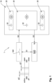
- Fig. 1 shows a method 1 according to the invention in connection with a subsystem 20 to be monitored of a power supply system 10 consisting of several subsystems 20.
- step S1 the subsystem 20 to be monitored is cyclically and briefly disconnected for the duration of a measuring time interval ⁇ T by means of all-pole semiconductor isolating switches SW.
- the semiconductor isolating switches SW are in the open state and the subsystem thus separated 20 continues to operate without interruption from the energy storage devices 22 present in this subsystem 20 in accordance with step S2.
- an insulation monitoring device IMD is active during the measuring time interval ⁇ T in order to determine the insulation resistance R f of the disconnected subsystem 20 within the measuring time interval ⁇ T or to continue the measurement of the insulation resistance R f and thus continuously increase the accuracy of the insulation resistance monitoring.
- FIG. 2 is a functional block diagram of an electrical circuit arrangement 2 according to the invention in a 3AC power supply system 10.
- the 3AC power supply system 10 comprises active conductors L1, L2, L3 and a protective conductor (earth) PE.
- the subsystem 20 with energy storage devices 22 is connected to this power supply system 10.
- the electrical circuit arrangement 2 comprises an insulation monitoring device IMD designed according to the standard IEC 61557-8, which is connected between the active conductors L1, L2, L3 of the subsystem 20 and earth PE, as well as the all-pole semiconductor disconnectors SW.
- the semiconductor isolating switches SW cyclically disconnect the subsystem 20 to be monitored from the main system for the duration of the measuring time interval ⁇ T (step S1), whereby - indicated by the connection designated S1 between the semiconductor isolating switches SW and the insulation monitoring device IMD - a measurement of the insulation resistance R f of the subsystem 20 is carried out synchronously with the switching state of the semiconductor isolating switches SW during the measuring time interval ⁇ T.
- step S3, Fig. 1 With the energy storage devices 22 present in the subsystem 20, continuous operation of the subsystem 20 is ensured even during the measuring time intervals ⁇ T in the disconnected state (step S3, Fig. 1 ).
- Fig. 3 shows the electrical circuit arrangement 2 in a DC power supply system 10 with active conductors L+, L-. The difference to the Fig. 2 The arrangement described consists solely in the two-pole coupling of the insulation monitoring device IMD and the two-pole design of the semiconductor disconnector SW.
- the representation in Fig. 4 is based on the arrangement in Fig. 2 for insulation monitoring in a 3AC power supply system 10.
- a semiconductor rectifier 30 is installed here as an all-pole semiconductor isolating switch SW. Below a load current threshold value I L to be specified, the subsystem 20 can be considered as disconnected, so that the insulation monitoring device IMD is activated during these measuring time intervals ⁇ T in which there is no or only a small load current flow.
- the ohmic leakage currents of the semiconductor rectifier flowing during the measuring time intervals ⁇ T are taken into account when determining the insulation resistance R f of the subsystem 20.
Landscapes
- Physics & Mathematics (AREA)
- General Physics & Mathematics (AREA)
- Measurement Of Resistance Or Impedance (AREA)
Applications Claiming Priority (1)
| Application Number | Priority Date | Filing Date | Title |
|---|---|---|---|
| DE102023116532.1A DE102023116532B3 (de) | 2023-06-23 | 2023-06-23 | Verfahren und elektrische Schaltungsanordnung zur selektiven Isolationsüberwachung in einem Stromversorgungssystem mit abtrennbaren Subsystemen |
Publications (2)
| Publication Number | Publication Date |
|---|---|
| EP4481406A1 true EP4481406A1 (fr) | 2024-12-25 |
| EP4481406B1 EP4481406B1 (fr) | 2025-12-31 |
Family
ID=91617188
Family Applications (1)
| Application Number | Title | Priority Date | Filing Date |
|---|---|---|---|
| EP24183029.8A Active EP4481406B1 (fr) | 2023-06-23 | 2024-06-19 | Procédé et circuit électrique pour la surveillance sélective de l'isolation dans un système d'alimentation électrique avec sous-systèmes séparables |
Country Status (3)
| Country | Link |
|---|---|
| US (1) | US12372570B2 (fr) |
| EP (1) | EP4481406B1 (fr) |
| DE (1) | DE102023116532B3 (fr) |
Citations (6)
| Publication number | Priority date | Publication date | Assignee | Title |
|---|---|---|---|---|
| EP1687646A1 (fr) | 2003-11-24 | 2006-08-09 | Dipl.-Ing. Walther Bender GmbH & Co. KG | Procede pour determiner la resistance d'isolement ohmique |
| EP2386870B1 (fr) * | 2010-03-16 | 2017-11-29 | Adensis GmbH | Procédé de test d'isolation pour grandes installations photovoltaïques |
| EP2851692B1 (fr) | 2013-09-19 | 2019-06-12 | Bender GmbH & Co. KG | Système de recherche de défaut d'isolation doté d'une alimentation à sélection de branchement et système de surveillance d'isolation sélectif ainsi que procédé de détermination d'une impédance de ligne inter-automatique entre deux sous-systèmes |
| EP2256506B1 (fr) * | 2009-05-27 | 2019-07-03 | Bender GmbH & Co. KG | Procédé et dispositif de surveillance de l'isolation de réseaux à courant continu et à courant alternatif non mis à la terre |
| EP3139188B1 (fr) * | 2015-09-03 | 2019-11-20 | Bender GmbH & Co. KG | Procédé et dispositif de recherche d'erreur d'isolation comprenant une détermination adaptative de courant de test |
| DE102018121979A1 (de) | 2018-09-10 | 2020-03-12 | Bender Gmbh & Co. Kg | Verfahren zur Isolationsüberwachung eines Umrichter-gespeisten Stromversorgungssystems |
Family Cites Families (4)
| Publication number | Priority date | Publication date | Assignee | Title |
|---|---|---|---|---|
| DE102013209142A1 (de) | 2013-05-16 | 2014-11-20 | Bayerische Motoren Werke Aktiengesellschaft | Verfahren zur Ermittlung eines Isolationswiderstands eines mehrere Teilnetze umfassenden Energieversorgungsnetzwerks eines Fahrzeugs |
| DE102018102959A1 (de) * | 2018-02-09 | 2019-08-14 | Bender Gmbh & Co. Kg | Vorrichtung und Verfahren für eine Isolationsüberwachung mit Erkennung eines fehlerbehafteten Außenleiters in einem 3-phasigen ungeerdeten Stromversorgungssystem |
| DE102019103396B3 (de) * | 2019-02-12 | 2020-07-02 | Bender Gmbh & Co. Kg | Verfahren und Geräte zur Bestimmung der Elemente eines dielelektrischen Ersatzschaltbildes für eine Isolierung eines elektrischen Systems |
| DE102020114906B4 (de) * | 2020-06-04 | 2023-06-29 | Bender Gmbh & Co. Kg | Schutzkontaktsteckdose und Verfahren zur Isolationsfehlerlokalisierung in einem ungeerdeten Stromversorgungssystem mit Isolationsüberwachung |
-
2023
- 2023-06-23 DE DE102023116532.1A patent/DE102023116532B3/de active Active
-
2024
- 2024-06-19 EP EP24183029.8A patent/EP4481406B1/fr active Active
- 2024-06-20 US US18/749,527 patent/US12372570B2/en active Active
Patent Citations (6)
| Publication number | Priority date | Publication date | Assignee | Title |
|---|---|---|---|---|
| EP1687646A1 (fr) | 2003-11-24 | 2006-08-09 | Dipl.-Ing. Walther Bender GmbH & Co. KG | Procede pour determiner la resistance d'isolement ohmique |
| EP2256506B1 (fr) * | 2009-05-27 | 2019-07-03 | Bender GmbH & Co. KG | Procédé et dispositif de surveillance de l'isolation de réseaux à courant continu et à courant alternatif non mis à la terre |
| EP2386870B1 (fr) * | 2010-03-16 | 2017-11-29 | Adensis GmbH | Procédé de test d'isolation pour grandes installations photovoltaïques |
| EP2851692B1 (fr) | 2013-09-19 | 2019-06-12 | Bender GmbH & Co. KG | Système de recherche de défaut d'isolation doté d'une alimentation à sélection de branchement et système de surveillance d'isolation sélectif ainsi que procédé de détermination d'une impédance de ligne inter-automatique entre deux sous-systèmes |
| EP3139188B1 (fr) * | 2015-09-03 | 2019-11-20 | Bender GmbH & Co. KG | Procédé et dispositif de recherche d'erreur d'isolation comprenant une détermination adaptative de courant de test |
| DE102018121979A1 (de) | 2018-09-10 | 2020-03-12 | Bender Gmbh & Co. Kg | Verfahren zur Isolationsüberwachung eines Umrichter-gespeisten Stromversorgungssystems |
Also Published As
| Publication number | Publication date |
|---|---|
| US20240426894A1 (en) | 2024-12-26 |
| EP4481406B1 (fr) | 2025-12-31 |
| DE102023116532B3 (de) | 2024-10-02 |
| US12372570B2 (en) | 2025-07-29 |
Similar Documents
| Publication | Publication Date | Title |
|---|---|---|
| EP3987297B1 (fr) | Procédé et onduleur photovoltaïque destinés à la détermination de la résistance d'isolement d'une installation photovoltaïque contre la terre | |
| EP3625863B1 (fr) | Localisation d'un défaut de terre dans un réseau it | |
| DE102011076320B4 (de) | Erdungsüberwachungs-Vorrichtung und Ladesystem | |
| EP3598151B1 (fr) | Procédé et dispositif de détermination de la répartition d'une résistance totale d'isolement et de la répartition d'une capacité totale de dérivation du réseau dans un système d'alimentation en courant isolé terre | |
| DE102014201044B3 (de) | Isolationsüberwachungsvorrichtung zur simultanen Überwachung von Netzabschnitten eines ungeerdeten Stromversorgungssystems | |
| DE69734879T2 (de) | Drahtlose selektive auslösung für parallelgeschaltete wechselstromsysteme | |
| EP3059828B1 (fr) | Dispositif et procede de detection de courant differentiel | |
| DE112010001977T5 (de) | Verfahren und Vorrichtungen zur Fehlerstromschutzüberwachung unter Verwendung eines einzigen Transformators | |
| DE102015208725B3 (de) | Verfahren und Vorrichtung zur Abschaltung eines Isolationsfehler-behafteten Anlagenteils eines ungeerdeten Stromversorgungssystems | |
| EP3206040B1 (fr) | Méthode et appareil pour la détection d'une interruption d'une connection à la terre | |
| EP1887675A2 (fr) | Installation photovoltaïque dotée d'une mesure de la résistance d'isolement de générateurs solaires et son procédé de fonctionnement | |
| DE10205381A1 (de) | Verfahren und Einrichtung zur Isolationsüberwachung eines Gleichstromnetzes | |
| DE102018102959A1 (de) | Vorrichtung und Verfahren für eine Isolationsüberwachung mit Erkennung eines fehlerbehafteten Außenleiters in einem 3-phasigen ungeerdeten Stromversorgungssystem | |
| EP3435504A2 (fr) | Procédé, ensembles de circuit électriques et appareils de surveillance de l'isolation pour une surveillance d'isolation résistante au brouillage d'un système d'alimentation électrique pourvu d'un convertisseur | |
| EP2796886B1 (fr) | Agencement de circuit pour la localisation de défauts d'isolement | |
| DE102015214615A1 (de) | Verfahren und Vorrichtungen zur erweiterten Isolationsfehlersuche mit multifunktionalem Prüfstrom | |
| EP3157113A1 (fr) | Dispositif de protection d'un défaut d'isolement dans un réseau électrique non mis à la masse | |
| DE102007017543A1 (de) | Verfahren zur Entfernungsortung von Erdschlüssen | |
| EP3931926B1 (fr) | Détection d'une perte à la terre dans un réseau à courant continu | |
| EP0045113B1 (fr) | Procédé et dispositif pour localiser des défauts à la terre | |
| DE102016100671A1 (de) | Verfahren und Vorrichtung zur Kurzschlussüberwachung einer Drehstromlast | |
| DE102014103321A1 (de) | Isolationsüberwachung für reihenkompensierte Wicklungen eines kontaktlosen Energieübertragungssystems | |
| EP3943954B1 (fr) | Agencement de circuit permettant de localiser des défauts d'isolation | |
| EP2672280B1 (fr) | Surveillance des défauts d'isolation avec affichage de la qualité des signaux | |
| DE102023116532B3 (de) | Verfahren und elektrische Schaltungsanordnung zur selektiven Isolationsüberwachung in einem Stromversorgungssystem mit abtrennbaren Subsystemen |
Legal Events
| Date | Code | Title | Description |
|---|---|---|---|
| PUAI | Public reference made under article 153(3) epc to a published international application that has entered the european phase |
Free format text: ORIGINAL CODE: 0009012 |
|
| STAA | Information on the status of an ep patent application or granted ep patent |
Free format text: STATUS: THE APPLICATION HAS BEEN PUBLISHED |
|
| AK | Designated contracting states |
Kind code of ref document: A1 Designated state(s): AL AT BE BG CH CY CZ DE DK EE ES FI FR GB GR HR HU IE IS IT LI LT LU LV MC ME MK MT NL NO PL PT RO RS SE SI SK SM TR |
|
| STAA | Information on the status of an ep patent application or granted ep patent |
Free format text: STATUS: REQUEST FOR EXAMINATION WAS MADE |
|
| 17P | Request for examination filed |
Effective date: 20250116 |
|
| GRAP | Despatch of communication of intention to grant a patent |
Free format text: ORIGINAL CODE: EPIDOSNIGR1 |
|
| STAA | Information on the status of an ep patent application or granted ep patent |
Free format text: STATUS: GRANT OF PATENT IS INTENDED |
|
| RIC1 | Information provided on ipc code assigned before grant |
Ipc: G01R 27/18 20060101AFI20250630BHEP Ipc: G01R 31/52 20200101ALI20250630BHEP |
|
| INTG | Intention to grant announced |
Effective date: 20250804 |
|
| GRAS | Grant fee paid |
Free format text: ORIGINAL CODE: EPIDOSNIGR3 |
|
| GRAA | (expected) grant |
Free format text: ORIGINAL CODE: 0009210 |
|
| STAA | Information on the status of an ep patent application or granted ep patent |
Free format text: STATUS: THE PATENT HAS BEEN GRANTED |
|
| AK | Designated contracting states |
Kind code of ref document: B1 Designated state(s): AL AT BE BG CH CY CZ DE DK EE ES FI FR GB GR HR HU IE IS IT LI LT LU LV MC ME MK MT NL NO PL PT RO RS SE SI SK SM TR |
|
| REG | Reference to a national code |
Ref country code: CH Ref legal event code: F10 Free format text: ST27 STATUS EVENT CODE: U-0-0-F10-F00 (AS PROVIDED BY THE NATIONAL OFFICE) Effective date: 20251231 Ref country code: GB Ref legal event code: FG4D Free format text: NOT ENGLISH |
|
| REG | Reference to a national code |
Ref country code: DE Ref legal event code: R096 Ref document number: 502024000574 Country of ref document: DE |
|
| REG | Reference to a national code |
Ref country code: IE Ref legal event code: FG4D Free format text: LANGUAGE OF EP DOCUMENT: GERMAN |
|
| P01 | Opt-out of the competence of the unified patent court (upc) registered |
Free format text: CASE NUMBER: UPC_APP_0000387_4481406/2026 Effective date: 20260106 |
|
| REG | Reference to a national code |
Ref country code: LT Ref legal event code: MG9D |
|
| PG25 | Lapsed in a contracting state [announced via postgrant information from national office to epo] |
Ref country code: NO Free format text: LAPSE BECAUSE OF FAILURE TO SUBMIT A TRANSLATION OF THE DESCRIPTION OR TO PAY THE FEE WITHIN THE PRESCRIBED TIME-LIMIT Effective date: 20260331 |
|
| PG25 | Lapsed in a contracting state [announced via postgrant information from national office to epo] |
Ref country code: HR Free format text: LAPSE BECAUSE OF FAILURE TO SUBMIT A TRANSLATION OF THE DESCRIPTION OR TO PAY THE FEE WITHIN THE PRESCRIBED TIME-LIMIT Effective date: 20251231 Ref country code: FI Free format text: LAPSE BECAUSE OF FAILURE TO SUBMIT A TRANSLATION OF THE DESCRIPTION OR TO PAY THE FEE WITHIN THE PRESCRIBED TIME-LIMIT Effective date: 20251231 |
|
| PG25 | Lapsed in a contracting state [announced via postgrant information from national office to epo] |
Ref country code: RS Free format text: LAPSE BECAUSE OF FAILURE TO SUBMIT A TRANSLATION OF THE DESCRIPTION OR TO PAY THE FEE WITHIN THE PRESCRIBED TIME-LIMIT Effective date: 20260331 |
|
| PG25 | Lapsed in a contracting state [announced via postgrant information from national office to epo] |
Ref country code: LV Free format text: LAPSE BECAUSE OF FAILURE TO SUBMIT A TRANSLATION OF THE DESCRIPTION OR TO PAY THE FEE WITHIN THE PRESCRIBED TIME-LIMIT Effective date: 20251231 |