EP4481420A1 - Untersuchungssystem mittels choudhmagnetischer resonanz mit leicht zu wartendem sensor - Google Patents
Untersuchungssystem mittels choudhmagnetischer resonanz mit leicht zu wartendem sensor Download PDFInfo
- Publication number
- EP4481420A1 EP4481420A1 EP23179931.3A EP23179931A EP4481420A1 EP 4481420 A1 EP4481420 A1 EP 4481420A1 EP 23179931 A EP23179931 A EP 23179931A EP 4481420 A1 EP4481420 A1 EP 4481420A1
- Authority
- EP
- European Patent Office
- Prior art keywords
- magnetic resonance
- electrical energy
- examination system
- resonance examination
- sensor
- Prior art date
- Legal status (The legal status is an assumption and is not a legal conclusion. Google has not performed a legal analysis and makes no representation as to the accuracy of the status listed.)
- Withdrawn
Links
Images


Classifications
-
- G—PHYSICS
- G01—MEASURING; TESTING
- G01R—MEASURING ELECTRIC VARIABLES; MEASURING MAGNETIC VARIABLES
- G01R33/00—Arrangements or instruments for measuring magnetic variables
- G01R33/20—Arrangements or instruments for measuring magnetic variables involving magnetic resonance
- G01R33/28—Details of apparatus provided for in groups G01R33/44 - G01R33/64
Definitions
- the invention relates to the field of magnetic resonance examination, and in particular to a magnetic resonance examination system comprising a sensor for measuring physical quantities that are indicative for the operational status of the magnetic resonance examination system and/or for measuring the vital signs of a patient to be examined in the magnetic examination system and for outputting respective data, and an electrical energy storage device for storing electrical energy and for providing the sensor with electrical energy.
- a patient undergoing magnetic resonance (MR) examination e.g. in a magnetic resonance imaging (MRI) system is typically positioned in a narrow bore within a MR magnet.
- the patient may be remotely monitored to determine vital signs of the patient, e.g. heartbeat, respiration, temperature and blood oxygen.
- a typical remote monitoring system provides in-bore sensors on the patient connected by electrical or optical cables to a monitoring unit outside of the bore. Connecting an in-bore sensor to a monitoring unit may be done with long runs of electrical or optical cables. Such cables may be a problem because they are cumbersome and can interfere with access to the patient and free movement of personnel.
- the magnetic resonance examination system typically comprises sensor arrangements for measuring physical quantities that are indicative for the operational status of the magnetic resonance examination system. It is preferred that such sensors communicate wirelessly with a monitoring arrangement, too.
- a wireless patient monitor for MRI which provides for on-board filtering of physiological signals from the patient to provide improved assessment and processing of MRI noise before the signal is affected by the transmission process.
- a system of powering of a wireless patient monitor using capacitors is also described.
- a radio frequency (RF) transmit-receive coil for a MRI system with an integrated vital signs detector for the detection of vital signs of a patient within the MRI system is described, whereby contact sensors directly attached to the body of the patient, are replaced by a contactless system for monitoring vital signs, which makes it much easier to measure vital signs of the patient.
- RF radio frequency
- a RF transmit-receive coil comprising a vital signs detector wherein the vital signs detector is integrated in the RF transmit-receive coil, wherein a pair of electrically conducting coil elements of the RF transmit-receive coil forms the vital signs detector, wherein the vital signs detector is a capacitive vital signs detector, the capacitive vital signs detector being adapted for receiving capacitive vital signs signals.
- electrical energy is generated from movements of the whole energy harvesting assembly or at least a part of the energy harvesting assembly.
- Such movements can be different kinds of movements including but not limited to linear movements, movements along a curved line, harmonic movements, movements with constant velocity, accelerated movements and vibrations.
- piezoelectric materials works by converting mechanical stress or strain into electrical energy, for example when the sensor is moved.
- Piezoelectric materials exhibit a unique property called the piezoelectric effect, which is the ability to generate an electric charge in response to mechanical stress or deformation.
- Piezoelectric materials are usually crystals, ceramics, or polymers that exhibit the piezoelectric effect. Common examples include quartz, lead zirconate titanate (PZT), and polyvinylidene fluoride (PVDF).
- PZT lead zirconate titanate
- PVDF polyvinylidene fluoride
- Electrodynamic or inductive generators works by converting mechanical energy, typically in the form of rotational or linear motion, into electrical energy through the principle of electromagnetic induction.
- Electrodynamic or inductive generators require a source of mechanical energy to drive their motion.
- the motion which is used for the generation of electrical energy is the movement of the energy harvesting assembly.
- An electrodynamic generator consists of two main components - a rotor and a stator.
- the rotor is the rotating part of the generator, while the stator is the stationary part.
- Both the rotor and stator have conductive coils, preferably made of copper or aluminum wire, wound around a magnetic core, such as iron or steel.
- the mechanical energy input causes the rotor to rotate or oscillate relative to the stator.
- Electrostatic generators can also be used to generate electrical energy from movements like vibrations. They are similar to an electrical capacitor in which one capacitor plate is suspended so that it can move relative to the other capacitor plate. By charging the capacitor when the capacitor plates are farther apart and discharging the capacitor when the plates are nearer to each other electrical energy can be generated.
- the output power depends on the capacitance of the capacitor and its charging voltage.
- the electrical energy storage device for storing electrical energy is a supercapacitor or a rechargeable microbattery.
- a supercapacitor also known as an ultracapacitor, is an electrochemical energy storage device that can store and release large amounts of electrical energy quickly.
- Supercapacitors work by storing charge on the surface of two electrodes separated by an electrolyte. Unlike batteries, which store energy through chemical reactions, supercapacitors store energy in an electric field. This allows them to charge and discharge quickly, typically in a matter of seconds or less, and to last for a much longer number of charge/discharge cycles than traditional batteries. Supercapacitors are particularly useful in situations where quick bursts of energy are needed.
- the movement of at least a part of the energy harvesting assembly may be achieved in different ways, according to a preferred embodiment of the invention, the movement of at least a part of the energy harvesting assembly is achieved by having the energy harvesting assembly attached to a movable part of the magnetic resonance examination system.
- the movement of the movable part may be initiated by a motor or even by hand, i.e. by handling the movable part by an operator of the system. In this way, a movement of the energy harvesting assembly is achieved together with the movement of movable part of the magnetic resonance examination system.
- the movable part of the magnetic resonance examination system is a movable patient table of the magnetic resonance system.
- the generation of electrical energy by the energy harvesting device may be achieved by jogging the patient table to which the energy harvesting assembly is attached back and forth in a predefined way.
- the movable part is a gradient coil of the magnetic resonance system, preferably a gradient coil.
- a gradient coil is an essential component of a magnetic resonance examination system that is responsible for creating the spatially varying magnetic field required to produce high-resolution images of the human body.
- a gradient coil system typically comprises three sets of coils, one for each of the three spatial dimensions (x, y, and z). When a current is passed through the gradient coils, they produce a linear magnetic field that varies along the length of the magnetic resonance scanner. By controlling the strength and timing of these magnetic field gradients, magnetic resonance scanners can precisely localize the source of the magnetic signals emanating from the human body and generate high-resolution images. Gradient coils are also used to encode spatial information into the magnetic resonance signal. By applying a series of gradient pulses with different amplitudes and directions, the scanner can encode spatial information into the magnetic resonance signal, allowing for the reconstruction of detailed three-dimensional images of the human body.
- the step of moving the movable part in a predefined way is performed by energizing a gradient coil, to which the energy harvesting assembly is attached in a predefined way.
- the generation of electrical energy by the energy harvesting device may be achieved by energizing the gradient coil coil to which the energy harvesting assembly is attached in a predefined way.
- This makes it possible to convert mechanical vibration energy into electrical energy.
- the conversion makes use of resonance effects which makes it possible to sweep a gradient coil frequency into the regime of optimum power transfer.
- the senor, the electrical energy storage device and the energy harvesting device are provided separate from each other in the magnetic resonance examination system.
- the sensor, the electrical energy storage device and the energy harvesting assembly together form a sensor arrangement, which is arranged within a common housing. In this way, a respective sensor always carries its own energy supply and, therefore, can be applied in the magnetic resonance examination system in a versatile way.
- the energy harvesting assembly may be operated on different principles.
- the energy harvesting assembly is equipped with a device comprising piezoelectric material for electrical energy generation.
- the energy harvesting assembly is equipped with an electrodynamic generator or an inductive generator for electrical energy generation.
- the magnetic resonance examination system comprises a monitoring arrangement for monitoring the data output by the sensor, and a wireless communication system for communication of data from the sensor to the monitoring arrangement to derive an operational status and/or patient vital sign information.
- the wireless communication system comprises a transmitting device for transmitting data from the sensor and a receiving device for receiving data transmitted by the transmitting device at the monitoring arrangement, and that the transmitting device is powered by electrical energy generated by the energy harvesting assembly. In this way, a self-sufficient system can be provided.
- the invention also relates to a method of operating a magnetic resonance examination system, the magnetic resonance examination system comprising:
- the method further comprises the following method steps:
- the senor may always be provided with sufficient electrical energy.
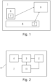
- Fig. 1 schematically depicts a magnetic resonance examination 1 system according to a preferred embodiment of the invention.
- the magnetic resonance examination system 1 comprises, inter alia, a monitoring arrangement 9, a movable patient table 5 and a set of gradient coils from which here only a single gradient coil 6 is shown. Both, the movable patient table 5 and the gradient coil 6 are equipped with a sensor arrangement 7.
- the sensor arrangements 7 comprise a housing 8 which carries a sensor 2, an electrical energy storage device 3 for storing electrical energy and for providing the sensor 2 with electrical energy, and an energy harvesting assembly 4 for generating electrical power from kinetic energy received by mechanical motion of a part of the energy harvesting assembly 4 and for transferring this electrical energy to the electrical energy storage device 3.
- the energy storage device 3 is a supercapacitor.
- the sensor 2 may be a sensor for measuring physical quantities that are indicative for the operational status of the magnetic resonance examination system 1 and/or for measuring the vital signs of a patient to be examined in the magnetic examination system 1 and for outputting respective data. This data is transmitted to the monitoring arrangement 9 which is used for monitoring the data output by the sensor 2.
- a wireless communication system 10 is provided for communication of data from the sensor 2 to the monitoring arrangement 9 to derive an operational status and/or patient vital sign information.
- This wireless communication system 10 comprises a transmitting device 11 which is arranged within the housing 8 of the sensor arrangement 7 and a receiving device 12 which is part of the monitoring arrangement 9. Data which in this way is wirelessly transmitted from the sensor arrangement 7 to the monitoring arrangement 9 may be displayed on a display 13 of the monitoring arrangement 9.
- the sensor 2 and the transmitting device 11 are both powered by electrical energy which is generated by the energy harvesting assembly 4.
- the energy harvesting assembly 4 is configured for generating electrical power from kinetic energy received by mechanical motion of a part of the energy harvesting assembly 4.
- the energy harvesting assembly 4 may be equipped with a device 15 comprising piezoelectric material for electrical energy generation as schematically depicted in Fig. 4 .
- the energy harvesting assembly 4 is equipped with an electrodynamic generator 16 as schematically depicted in Fig. 5 or with an inductive generator 17 for electrical energy generation as schematically depicted in Fig. 6 .
- step S1 it is detected whether the electrical energy storage device 3 of the sensor arrangement 7 which is attached to the patient table 5 is in a charging state which is below a predefined lower threshold. If it is detected that the charging state of the electrical energy storage device 3 is below the predefined lower threshold, in step S2, the patient table 5 to which the sensor arrangement 7 is jogged back and forth in a predefined way. In this way, the sensor arrangement 7 is moved together with the patient table 5 which means that electrical energy is generated by the energy harvesting assembly 4 of the sensor arrangement 7 and the electrical energy storage device is charged.
- a sensor arrangement 7 may also be attached to a gradient coil 6 of the magnetic resonance examination system 1, especially to a gradient coil.
- movement of the gradient coil 6 together with the attached sensor arrangement may be achieved by energizing the gradient coil 6.
- the energy conversion may make use of resonance effects which makes it possible to sweep a gradient coil frequency into the regime of optimum power transfer.
- magnetic resonance examination system 1 sensor 2 electrical energy storage device 3 energy harvesting assembly 4 patient table 5 gradient coil 6 sensor arrangement 7 housing 8 monitoring arrangement 9 wireless communication system 10 transmitting device 11 receiving device 12 display 13 interface 14 device comprising piezoelectric material 15 electrodynamic generator 16 inductive generator 17
Landscapes
- Physics & Mathematics (AREA)
- Condensed Matter Physics & Semiconductors (AREA)
- General Physics & Mathematics (AREA)
- Magnetic Resonance Imaging Apparatus (AREA)
Priority Applications (1)
| Application Number | Priority Date | Filing Date | Title |
|---|---|---|---|
| EP23179931.3A EP4481420A1 (de) | 2023-06-19 | 2023-06-19 | Untersuchungssystem mittels choudhmagnetischer resonanz mit leicht zu wartendem sensor |
Applications Claiming Priority (1)
| Application Number | Priority Date | Filing Date | Title |
|---|---|---|---|
| EP23179931.3A EP4481420A1 (de) | 2023-06-19 | 2023-06-19 | Untersuchungssystem mittels choudhmagnetischer resonanz mit leicht zu wartendem sensor |
Publications (1)
| Publication Number | Publication Date |
|---|---|
| EP4481420A1 true EP4481420A1 (de) | 2024-12-25 |
Family
ID=86899267
Family Applications (1)
| Application Number | Title | Priority Date | Filing Date |
|---|---|---|---|
| EP23179931.3A Withdrawn EP4481420A1 (de) | 2023-06-19 | 2023-06-19 | Untersuchungssystem mittels choudhmagnetischer resonanz mit leicht zu wartendem sensor |
Country Status (1)
| Country | Link |
|---|---|
| EP (1) | EP4481420A1 (de) |
Citations (7)
| Publication number | Priority date | Publication date | Assignee | Title |
|---|---|---|---|---|
| WO2007134143A2 (en) | 2006-05-12 | 2007-11-22 | Invivo Corporation | Wireless patient parameter sensors for use in mri |
| US20160228005A1 (en) * | 2013-09-17 | 2016-08-11 | The Board Of Trustees Of The Leland Stanford Junior University | Apparatus for Obtaining High-quality Optical Images in a Magnetic Resonance Imaging System |
| US20170176551A1 (en) * | 2014-03-31 | 2017-06-22 | Koninklijke Philips N.V. | Receive coils with low-loss detune circuits for magnetic resonance (mr) systems and method of operation thereof |
| US20170336484A1 (en) * | 2014-12-08 | 2017-11-23 | Koninklijke Philips N.V. | Radio frequency receive coil for use in magnetic resonance imaging systems with disconnection warning |
| US20190053777A1 (en) * | 2017-08-16 | 2019-02-21 | Siemens Healthcare Gmbh | Sensor array in a component of an imaging device |
| DE102018126909A1 (de) * | 2018-10-29 | 2020-04-30 | Hahn-Schickard-Gesellschaft für angewandte Forschung e.V. | Energiesammler zur Gewinnung elektrischer Energie bei zeitlich veränderbaren Magnetfeldern |
| WO2021130203A1 (en) | 2019-12-23 | 2021-07-01 | Koninklijke Philips N.V. | Rf coil with integrated vital signs detector |
-
2023
- 2023-06-19 EP EP23179931.3A patent/EP4481420A1/de not_active Withdrawn
Patent Citations (7)
| Publication number | Priority date | Publication date | Assignee | Title |
|---|---|---|---|---|
| WO2007134143A2 (en) | 2006-05-12 | 2007-11-22 | Invivo Corporation | Wireless patient parameter sensors for use in mri |
| US20160228005A1 (en) * | 2013-09-17 | 2016-08-11 | The Board Of Trustees Of The Leland Stanford Junior University | Apparatus for Obtaining High-quality Optical Images in a Magnetic Resonance Imaging System |
| US20170176551A1 (en) * | 2014-03-31 | 2017-06-22 | Koninklijke Philips N.V. | Receive coils with low-loss detune circuits for magnetic resonance (mr) systems and method of operation thereof |
| US20170336484A1 (en) * | 2014-12-08 | 2017-11-23 | Koninklijke Philips N.V. | Radio frequency receive coil for use in magnetic resonance imaging systems with disconnection warning |
| US20190053777A1 (en) * | 2017-08-16 | 2019-02-21 | Siemens Healthcare Gmbh | Sensor array in a component of an imaging device |
| DE102018126909A1 (de) * | 2018-10-29 | 2020-04-30 | Hahn-Schickard-Gesellschaft für angewandte Forschung e.V. | Energiesammler zur Gewinnung elektrischer Energie bei zeitlich veränderbaren Magnetfeldern |
| WO2021130203A1 (en) | 2019-12-23 | 2021-07-01 | Koninklijke Philips N.V. | Rf coil with integrated vital signs detector |
Non-Patent Citations (1)
| Title |
|---|
| PAVEL S. SEREGINOLEG I. BURMISTROVGEORGIY A. SOLOMAKHAEGOR I. KRETOVNIKITA A. OLEKHNOALEXEY P. SLOBOZHANYUK: "Energy-Harvesting Coil for Circularly Polarized Fields in Magnetic Resonance Imaging", PHYSICAL REVIEW, 2022, pages 004014 |
Similar Documents
| Publication | Publication Date | Title |
|---|---|---|
| Moss et al. | A bi-axial magnetoelectric vibration energy harvester | |
| CN101588754B (zh) | 用于在mri中使用的无线患者参数传感器 | |
| AU2013254931B2 (en) | Vibration energy conversion device | |
| Deterre et al. | Micro blood pressure energy harvester for intracardiac pacemaker | |
| Zhang et al. | Vibration energy harvesting based on magnet and coil arrays for watt-level handheld power source | |
| Ansari et al. | Experimental investigation of fan-folded piezoelectric energy harvesters for powering pacemakers | |
| Jiang et al. | Low-frequency energy harvesting using a laminated PVDF cantilever with a magnetic mass | |
| US20120283807A1 (en) | Energy Harvester Device For Autonomous Intracorporeal Capsule | |
| US20120280516A1 (en) | Vibration energy conversion device | |
| EP0275699A1 (de) | Isolierte Leistungsübertragung und Patientenüberwachungssystem mit Entstörung angewendet in Kernspinresonanz Apparaturen | |
| Kashiwao et al. | Optimization of rectifier circuits for a vibration energy harvesting system using a macro-fiber composite piezoelectric element | |
| CN105842100B (zh) | 一种电磁激励的无线qcm-d传感器检测系统 | |
| KR101381424B1 (ko) | 삽입형 무선 심전도 센서 장치 | |
| JP2018533351A (ja) | エネルギおよび/または信号を無線で伝達するため、エネルギおよび/または信号を他のエネルギ形態および/または信号形態に変換するためおよびシステムの周辺範囲でエネルギ形態および/または信号形態を適用および/または検出するためのシステム | |
| Halim et al. | Analysis of a dual-transduction receiver for electrodynamic wireless power transfer | |
| Koul et al. | A comparative analysis of different vibration based energy harvesting techniques for implantables | |
| EP4481420A1 (de) | Untersuchungssystem mittels choudhmagnetischer resonanz mit leicht zu wartendem sensor | |
| Deterre et al. | Micromachined piezoelectric spirals and ultra-compliant packaging for blood pressure energy harvesters powering medical implants | |
| WO2017139554A1 (en) | Piezoelectric energy harvester for human motion | |
| WO2023004346A1 (en) | Hybrid electromechanical transformer | |
| Mukherjee et al. | Experimental demonstration of miniaturized magnetoelectric wireless power transfer system for implantable medical devices | |
| Smith et al. | Dual-transduction electromechanical receiver for near-field wireless power transmission | |
| Mahmood et al. | Free battery-based energy harvesting techniques for medical devices | |
| Halim et al. | Piezoceramic electrodynamic wireless power receiver using torsion mode meandering suspension | |
| CN109570137A (zh) | 一种具有自诊断功能的超声波除垢装置 |
Legal Events
| Date | Code | Title | Description |
|---|---|---|---|
| PUAI | Public reference made under article 153(3) epc to a published international application that has entered the european phase |
Free format text: ORIGINAL CODE: 0009012 |
|
| STAA | Information on the status of an ep patent application or granted ep patent |
Free format text: STATUS: THE APPLICATION HAS BEEN PUBLISHED |
|
| AK | Designated contracting states |
Kind code of ref document: A1 Designated state(s): AL AT BE BG CH CY CZ DE DK EE ES FI FR GB GR HR HU IE IS IT LI LT LU LV MC ME MK MT NL NO PL PT RO RS SE SI SK SM TR |
|
| STAA | Information on the status of an ep patent application or granted ep patent |
Free format text: STATUS: THE APPLICATION IS DEEMED TO BE WITHDRAWN |
|
| 18D | Application deemed to be withdrawn |
Effective date: 20250626 |