EP4481424A1 - Système et procédé d'estimation d'angle d'arrivée (aoa) - Google Patents
Système et procédé d'estimation d'angle d'arrivée (aoa) Download PDFInfo
- Publication number
- EP4481424A1 EP4481424A1 EP24179694.5A EP24179694A EP4481424A1 EP 4481424 A1 EP4481424 A1 EP 4481424A1 EP 24179694 A EP24179694 A EP 24179694A EP 4481424 A1 EP4481424 A1 EP 4481424A1
- Authority
- EP
- European Patent Office
- Prior art keywords
- pdoa
- cir
- information
- aoa
- uwb
- Prior art date
- Legal status (The legal status is an assumption and is not a legal conclusion. Google has not performed a legal analysis and makes no representation as to the accuracy of the status listed.)
- Pending
Links
Images



Classifications
-
- G—PHYSICS
- G01—MEASURING; TESTING
- G01S—RADIO DIRECTION-FINDING; RADIO NAVIGATION; DETERMINING DISTANCE OR VELOCITY BY USE OF RADIO WAVES; LOCATING OR PRESENCE-DETECTING BY USE OF THE REFLECTION OR RERADIATION OF RADIO WAVES; ANALOGOUS ARRANGEMENTS USING OTHER WAVES
- G01S5/00—Position-fixing by co-ordinating two or more direction or position line determinations; Position-fixing by co-ordinating two or more distance determinations
- G01S5/02—Position-fixing by co-ordinating two or more direction or position line determinations; Position-fixing by co-ordinating two or more distance determinations using radio waves
- G01S5/0205—Details
- G01S5/0218—Multipath in signal reception
-
- H—ELECTRICITY
- H04—ELECTRIC COMMUNICATION TECHNIQUE
- H04W—WIRELESS COMMUNICATION NETWORKS
- H04W24/00—Supervisory, monitoring or testing arrangements
-
- G—PHYSICS
- G01—MEASURING; TESTING
- G01S—RADIO DIRECTION-FINDING; RADIO NAVIGATION; DETERMINING DISTANCE OR VELOCITY BY USE OF RADIO WAVES; LOCATING OR PRESENCE-DETECTING BY USE OF THE REFLECTION OR RERADIATION OF RADIO WAVES; ANALOGOUS ARRANGEMENTS USING OTHER WAVES
- G01S3/00—Direction-finders for determining the direction from which infrasonic, sonic, ultrasonic or electromagnetic waves, or particle emission, not having a directional significance, are being received
- G01S3/02—Direction-finders for determining the direction from which infrasonic, sonic, ultrasonic or electromagnetic waves, or particle emission, not having a directional significance, are being received using radio waves
- G01S3/14—Systems for determining direction or deviation from predetermined direction
- G01S3/46—Systems for determining direction or deviation from predetermined direction using antennas spaced apart and measuring phase or time difference between signals therefrom, i.e. path-difference systems
- G01S3/48—Systems for determining direction or deviation from predetermined direction using antennas spaced apart and measuring phase or time difference between signals therefrom, i.e. path-difference systems the waves arriving at the antennas being continuous or intermittent and the phase difference of signals derived therefrom being measured
-
- G—PHYSICS
- G01—MEASURING; TESTING
- G01S—RADIO DIRECTION-FINDING; RADIO NAVIGATION; DETERMINING DISTANCE OR VELOCITY BY USE OF RADIO WAVES; LOCATING OR PRESENCE-DETECTING BY USE OF THE REFLECTION OR RERADIATION OF RADIO WAVES; ANALOGOUS ARRANGEMENTS USING OTHER WAVES
- G01S5/00—Position-fixing by co-ordinating two or more direction or position line determinations; Position-fixing by co-ordinating two or more distance determinations
- G01S5/02—Position-fixing by co-ordinating two or more direction or position line determinations; Position-fixing by co-ordinating two or more distance determinations using radio waves
- G01S5/0205—Details
- G01S5/0244—Accuracy or reliability of position solution or of measurements contributing thereto
-
- H—ELECTRICITY
- H04—ELECTRIC COMMUNICATION TECHNIQUE
- H04B—TRANSMISSION
- H04B1/00—Details of transmission systems, not covered by a single one of groups H04B3/00 - H04B13/00; Details of transmission systems not characterised by the medium used for transmission
- H04B1/69—Spread spectrum techniques
- H04B1/7163—Spread spectrum techniques using impulse radio
-
- H—ELECTRICITY
- H04—ELECTRIC COMMUNICATION TECHNIQUE
- H04L—TRANSMISSION OF DIGITAL INFORMATION, e.g. TELEGRAPHIC COMMUNICATION
- H04L25/00—Baseband systems
- H04L25/02—Details ; arrangements for supplying electrical power along data transmission lines
- H04L25/0202—Channel estimation
- H04L25/0212—Channel estimation of impulse response
-
- H—ELECTRICITY
- H04—ELECTRIC COMMUNICATION TECHNIQUE
- H04W—WIRELESS COMMUNICATION NETWORKS
- H04W4/00—Services specially adapted for wireless communication networks; Facilities therefor
- H04W4/02—Services making use of location information
- H04W4/025—Services making use of location information using location based information parameters
- H04W4/026—Services making use of location information using location based information parameters using orientation information, e.g. compass
Definitions
- Angle and range information can be obtained using wireless communications technology, which has given rise to various applications that require angle (e.g., angle of arrival (AoA)) and range information.
- AoA angle of arrival
- range information can be obtained using wireless communications technology, which has given rise to various applications that require angle (e.g., angle of arrival (AoA)) and range information.
- AoA angle of arrival
- NNLoS Non Line of sight
- the channel between devices and the phase of signals may experience drastic changes and thus can result in less precise AoA estimates. Therefore, there is a need for a wireless communications technology that can distinguish between AoA estimates, e.g., distinguish good from bad AoA estimates and/or distinguish precise from imprecise AoA estimates.
- a wireless communications system includes a processor configured to obtain an angle of arrival (AoA) estimate from wireless signals; perform a Channel Impulse Response (CIR) analysis, and determine a confidence level for the AoA estimate based on the CIR analysis.
- AoA angle of arrival
- CIR Channel Impulse Response
- the processor is further configured to perform the CIR analysis to obtain multipath component information and phase difference of Arrival (PDoA) variance information.
- PoA phase difference of Arrival
- the multipath component information includes confidence information of a rising edge and confidence information of a main lobe width of complex CIR samples.
- the multipath component information further includes confidence information of a first valid index difference of the complex CIR samples.
- the multipath component information further includes confidence information of a first path index difference of the complex CIR samples.
- the multipath component information includes a combination of a confidence level of a rising edge and a confidence level of a main lobe width of complex CIR samples, a confidence level of a first valid index difference of the complex CIR samples, and a confidence level of a first path index difference of the complex CIR samples.
- the PDoA variance information includes a signal-to-noise (SNR) ratio variance at a PDoA index on complex CIR samples and PDoA drift information.
- SNR signal-to-noise
- the processor is further configured to analyze complex CIR samples to obtain confidence information of a rising edge and confidence information of a main lobe width of the complex CIR samples.
- the processor is further configured to obtain a PDoA slope value and PDoA ambiguous region information and to determine the confidence level for the AoA estimate based on the PDoA slope value and the PDoA ambiguous region information.
- the wireless signals include UWB signals.
- the wireless communications system further includes a multi-antenna UWB receiver configured to receive the UWB signals.
- a UWB system includes a multi-antenna UWB receiver arrangement configured to receive UWB signals and a processor operably connected to the multi-antenna UWB receiver arrangement and configured to obtain an angle of arrival (AoA) estimate from the UWB signals, perform a Channel Impulse Response (CIR) analysis by analyzing complex CIR samples of receivers of the multi-antenna UWB receiver arrangement and determine a confidence level for the AoA estimate based on the CIR analysis, and a storage unit configured to store the AoA estimate and the confidence level for the AoA estimate.
- AoA angle of arrival
- CIR Channel Impulse Response
- the processor is further configured to perform the CIR analysis to obtain multipath component information and PDoA variance information.
- the multipath component information includes confidence information of a rising edge and confidence information of a main lobe width of the complex CIR samples of the multi-antenna UWB receiver arrangement.
- the multipath component information further includes confidence information of a first valid index difference of the complex CIR samples of the multi-antenna UWB receiver arrangement.
- the multipath component information further includes confidence information of a first path index difference of the complex CIR samples of the multi-antenna UWB receiver arrangement.
- the PDoA variance information includes a SNR ratio variance at a PDoA index on the complex CIR samples of the multi-antenna UWB receiver arrangement and PDoA drift information.
- the processor is further configured to obtain a PDoA slope value and PDoA ambiguous region information and to determine the confidence level for the AoA estimate based on the CIR analysis, the PDoA slope value, and the PDoA ambiguous region information.
- a method for wireless communications involves obtaining an AoA estimate from wireless signals, performing a CIR analysis, and determining a confidence level for the AoA estimate based on the CIR analysis.
- Ultra-wide band refers to a wireless communication technology in which wireless signals are transmitted over a wide spectrum of frequency bands.
- UWB systems operate in the frequency range of 3 kHz to 300 GHz.
- Fig. 1 depicts an embodiment of a UWB communications system 100 in accordance with an embodiment of the invention.
- the UWB communications system 100 includes multiple UWB systems 102-1, ..., 102-N, where N is a positive integer that is greater than one.
- the UWB systems 102-1, ..., 102-N communicate with each other via UWB signals.
- the UWB systems may have a wide range of mobility and portability.
- at least one of the UWB systems is a handheld mobile device such as a cellular phone, a Smartphone, a Personal Digital Assistant (PDA), an Enterprise digital assistant (EDA), a handheld gaming device, or a wearable device.
- PDA Personal Digital Assistant
- EDA Enterprise digital assistant
- At least one of the UWB systems is a portable computing device such as a laptop computer, a netbook computer, or a tablet computer.
- the UWB communications system 100 depicted in Fig. 1 can be used in various applications, for example, in communications and indoor localization applications (e.g., within parking structures, shopping malls, airports, train stations, and hospitals).
- highly precise angle and range information of a device can be achieved with large bandwidths that UWB technology offers, which has given rise to various applications that require angle (e.g., AoA) and range information in device-to-device communications, smart homes, smart retails and smart enterprises, etc.
- AoA angle-to-device communications
- smart homes, smart retails and smart enterprises etc.
- the need to have precise angle and range information becomes important.
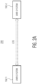
- Fig. 2A depicts a Line of sight (LoS) communications scenario 200 of the UWB communications system 100 depicted in Fig. 1 .
- LoS Line of sight
- the UWB system 102-1 communicates with the UWB system 102-2 in LoS.
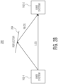
- Fig. 2B depicts a multi-path communications scenario 280 of the UWB communications system 100 depicted in Fig. 1 .
- the UWB system 102-1 communicates with the UWB system 102-2 in both LoS and in NLoS.
- a reflector 264 can reflect UWB signals from the UWB system 102-1 to the UWB system 102-2, and vice versa.
- the reflector 264 may be a surface of an object, for example, a frequency-selective surface (FSS), which is a repetitive surface configured to reflect, transmit or absorb electromagnetic fields on a frequency basis.
- FSS frequency-selective surface
- the UWB system 102-1 can communicate with the UWB system 102-2 directly in LoS without reflection.
- the UWB system 102-1 only communicates with the UWB system 102-2 in NLoS and does not communicate with the UWB system 102-2 directly in LoS without reflection.
- the communications channel between the UWB systems 102-1, 102-2 and phase of signals can experience drastic changes and thus can result in less precise AoA estimates.
- the UWB systems 102-1, 102-2 distinguish between good/precise AoA estimates from bad/imprecise AoA estimates.
- the UWB systems 102-1, 102-2 may distinguish between good/precise AoA estimates from bad/imprecise AoA estimates by having a confidence level on each AoA estimate.
- at least one of the UWB systems 102-1, 102-2 uses a Figure-of-Merit (FoM) algorithm to evaluate the communications channel conditions and the antenna characteristic curves and provides a confidence level on an AoA estimate.
- FoM Figure-of-Merit
- At least one of the UWB systems 102-1, 102-2 uses a FoM algorithm to identify bad/imprecise AoA estimates (e.g., AoA estimates with lower AoA FoM confidence level(s)), and to filter out the bad/imprecise AoA estimates and hence improve the average AoA estimation accuracy.
- Each AoA estimate may have an AoA FoM confidence level between zero to one, with one being the highest confidence level.
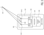
- Fig. 3 depicts an embodiment of the UWB systems 102-1, ..., 102-N of the UWB communications system 100 depicted in Fig. 1 .
- a UWB system 302 includes a dual-antenna UWB receiver arrangement or array 322, a processor 324 operably connected to the dual-antenna receiver, and a storage unit 326 for storing information related to the UWB system 302.
- the UWB system 302 depicted in Fig. 3 is one possible embodiment of the UWB systems 102-1, ..., 102-N depicted in Fig. 1 .
- the UWB system 302 may be implemented in hardware, firmware, and/or a combination of hardware, software, and/or firmware.
- the UWB system 302 or a component of the UWB system 302 is packaged as a stand-alone integrated circuit (IC) chip.
- the dual-antenna UWB receiver arrangement 322 can be implemented in at least one substrate, such as at least one semiconductor wafer.
- the dual-antenna UWB receiver arrangement is packaged as a stand-alone IC chip.
- the processor 324 can be implemented in at least one substrate, such as at least one semiconductor wafer.
- the processor 324 is packaged as a stand-alone IC chip.
- the dual-antenna UWB receiver arrangement 322 includes a first antenna 334-1, a second antenna 334-2, and an RF modem 338 configured to process (e.g., decode) received UWB signals from the first and second antennas.
- the RF modem 338 includes two receivers RX0, RX1 connected to the first antenna 334-1 and the second antenna 334-2, respectively, to process (e.g., decode) received UWB signals from the first and second antennas.
- the dual-antenna UWB receiver arrangement 322 also functions a transmitter, and the RF modem 338 is configured to decode received UWB signals from the first and second antennas and to encode UWB signals to be transmitted by the first and second antennas.
- the dual-antenna UWB receiver arrangement 322 includes at least one switch configured to switch the first antenna and/or the second antenna between transmitting outgoing UWB signals and receiving incoming UWB signals.
- the dual-antenna UWB receiver only has the capability of receiving UWB signals and does not include switch or switches to switch the first antenna and/or the second antenna between transmitting outgoing UWB signals and receiving incoming UWB signals.
- the UWB system 302 is shown in Fig. 3 as including two antennas 334-1, 334-2, in other embodiments, the UWB system 302 includes more than two antennas.
- the UWB system 302 is shown in Fig. 3 as including two receivers RX0, RX1, in other embodiments, the UWB system 302 includes more than two receivers.
- the processor 324 is configured to determine angle of arrival (AoA) information from the UWB signals received from the two antennas 334-1, 334-2 and to distinguish between good/precise AoA estimates from bad/imprecise AoA estimates.
- AoA information is related to an angle between a respective USB system having an antenna 354 and the UWB system 302 relative to a reference line (e.g., a horizon line or a vertical line).
- the processor distinguishes between good/precise AoA estimates from bad/imprecise AoA estimates by having a confidence level on each AoA estimate.
- the processor uses a Figure-of-Merit (FoM) algorithm, which may be stored in the storage unit 326, to evaluate the wireless communications channel conditions and the antenna characteristic curves of the UWB system 302 and provides a confidence level on an AoA estimate.
- FoM Figure-of-Merit
- the processor uses a FoM algorithm to identify bad/imprecise AoA estimates (e.g., AoA estimates with lower AoA FoM confidence level(s)), and to filter out the bad/imprecise AoA estimates and hence improve the average AoA estimation accuracy.
- each AoA estimate has an AoA FoM confidence level that is presented as a number from zero to one, with zero being the lowest confidence level and one being the highest confidence level.
- the confidence level can be represented by a different range of numbers, such as a range of numbers between one and one-hundred, although other numerical representations of the confidence level are possible.
- each AoA estimate has a confidence level that is presented as a non-number level.
- an AoA estimate may have a confidence level that is represented as high, medium, or low.
- the confidence level may be characterized in some other manner, such by colors (e.g., green as high confidence, yellow as medium confidence, and red as low confidence).
- the processor is a microcontroller, a digital signal processor (DSP), or a central processing unit (CPU).
- the processor includes a DSP processor configured to execute an FoM algorithm and a hardware processor (e.g., a reduced instruction set computer (RISC) processor such as an Advanced RISC Machines (ARM) processor) configured to compute final FoM results.
- RISC reduced instruction set computer
- ARM Advanced RISC Machines
- an angle ⁇ 1 between the respective UWB system with the antenna 354 and the UWB system 302 relative to a reference horizon line 380 is estimated by the processor from a difference between the time of arrival of a UWB radio pulse from the antenna 354 of the respective UWB system at the first antenna 334-1 of the dual-antenna UWB receiver and the time of arrival of the UWB radio pulse from the antenna 354 of the respective UWB system at the second antenna 334-2 of the dual-antenna UWB receiver.
- the processor 324 is configured to obtain an AoA estimate from UWB signals received at the first antenna 334-1 and the second antenna 334-2 and determine a confidence level for the AoA estimate based on an FoM algorithm. In some embodiments, the processor 324 obtains the AoA estimate by calculating, generating, and/or producing the AoA estimate. In other embodiments, the processor 324 obtains the AoA estimate by receiving or requesting the AoA estimate from other source(s) (e.g., the RF modem 338).
- other source(s) e.g., the RF modem 338
- the processor is further configured to perform a Channel Impulse Response (CIR) analysis by analyzing complex CIR samples of the receivers RX0, RX1 of the dual-antenna UWB receiver arrangement 322 and to determine the confidence level for the AoA estimate based on the CIR analysis.
- the processor is further configured to perform the CIR analysis to obtain multipath component information and phase difference of Arrival (PDoA) variance information.
- the multipath component information includes confidence information of a rising edge and confidence information of a main lobe width of the complex CIR samples of the dual-antenna UWB receiver arrangement 322.
- the multipath component information further includes confidence information of a first valid index difference of the complex CIR samples of the dual-antenna UWB receiver arrangement 322. In some embodiments, the multipath component information further includes confidence information of a first path index difference of the complex CIR samples of the dual-antenna UWB receiver arrangement 322. In some embodiments, the multipath component information includes a combination of a confidence level of a rising edge and a confidence level of a main lobe width of the complex CIR samples, a confidence level of a first valid index difference of the complex CIR samples, and a confidence level of a first path index difference of the complex CIR samples. In some embodiments, the PDoA variance information includes a signal-to-noise (SNR) ratio variance at a PDoA index on the complex CIR samples and PDoA drift information.
- SNR signal-to-noise
- the storage unit 326 is configured to store information related to the UWB system 302 (e.g., communications information and/or location information of the UWB system 302). In some embodiments, the storage unit stores an FoM algorithm and AoA estimations and FoM information of the AoA estimations.
- the storage unit can be implemented as read only memory (ROM), flash memory, random access memory (RAM), cache, or other type of storage device. Although the illustrated storage unit is shown as being separate from the processor, in some embodiments, the storage unit is implemented within the processor.
- a FoM algorithm used by the UWB system 302 takes into account the result of an AoA algorithm (e.g., AoA estimates).
- the FoM algorithm can take into account the calibration of PDoA curves.
- the FoM algorithm can also take into account the Channel Impulse Response (CIR) at each receiver RX0 or RX1, which provides information on the signal-to-noise ratio (SNR) and the phase of the signals.
- CIR Channel Impulse Response
- the FoM algorithm can incorporate the above information to qualify each sample as either good/accurate or bad/imprecise (e.g., based on a predefined threshold) at each receiving antenna and hence provide a confidence level based on the above three metrics.
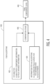
- Fig. 4 depicts a FoM algorithm 400 that can be used by the UWB system 302 depicted in Fig. 3 .
- the FoM algorithm 400 can be stored in the storage unit 326 and executed by the processor 324.
- the FoM algorithm 400 includes a CIR analysis stage 402 that considers CIR analysis information, which includes multipath component information and PDoA variance information.
- the FoM algorithm includes an AoA stage 404 that considers information from an AoA algorithm, which includes the calibration of PDoA curves for a corresponding antenna pair (e.g., the first antenna 334-1 and the second antenna 334-2 of the UWB system 302) and AoA estimates.
- the FoM algorithm can incorporate the above information at a combination stage 406 to provide a confidence level 408 of an AoA estimate.
- the complex CIR samples (e.g., CIR0 for the receiver RX0 and CIR1 for the receiver RX1 of the UWB system 302) can be used to obtain amplitude and phase information.
- the CIR analysis stage is a signal quality check stage. In the CIR analysis stage, the obtained CIR samples are evaluated to determine the signal quality as good or bad.
- Multipath Component Information (MPC):
- the multipath component information analysis can be used, for example, by the processor 324, to determine problematic multipath scenarios that can result in larger AoA errors because of multipath effects in the wireless communications channel of the UWB system 302.
- Fig. 5 depicts clean CIR amplitude and phase for a LoS wireless communications channel of the UWB system 302 depicted in Fig. 3
- Fig. 6 depicts multipath CIR amplitude and phase of the UWB system 302 depicted in Fig. 3 .
- pulse characteristics are obtained, for example, by the processor 324.
- Each receiver has an associated CIR.
- the main lobe width and the rising edge of the pulse is known. For example, in Fig. 5 , the main lobe width, ⁇ t (n) m is around 3.3 nanosecond (ns) and the rising edge, ⁇ t (n) re is around 2.5 nanoseconds (ns).
- the main lobe width and the rising edge deviate from these numbers for CIR1, which can be seen in Fig. 6 where the main lobe for CIR0 is between 767ns - 770ns, but for CIR1 is between 765ns-767ns.
- MainLobeWidthRef may be 3.3ns.
- first valid index difference is obtained, for example, by the processor 324.
- the first valid index is the first index at which a CIR sample magnitude is above a predefined threshold.
- the predefined threshold is determined based on the noise variance calculation and is referred to as the noise variance threshold.
- the first valid index may be determined for two receivers (e.g., the two receivers RX0, RX1 of the UWB system 302) using the corresponding CIRs. In some embodiments, if this difference in the first valid index between two receivers is greater than a pre-determined threshold, it indicates the presence of problematic multipath component. For example, in Fig.
- first path index difference is obtained, for example, by the processor 324.
- the first path index is the index of the peak of the main lobe of the pulse in the CIR.
- the difference in the first path indices of two receivers e.g., the two receivers RX0, RX1 of the UWB system 302
- the estimated first path is at 834.6 ns on both the CIRs.
- the estimated first path index on CIR0 is 769, whereas the value on CIR1 is 766.
- Multipath component information can be obtained, for example, by the processor 324 as a combination of the confidence level of the CIR rising edge, the confidence level of the CIR main lobe width, a confidence level of the first valid index difference, and a confidence level of the first path index difference.
- PDoA variance information is obtained, for example, by the processor 324.
- the PDoA variance information is mainly dependent on two factors, a signal-to-noise (SNR) ratio variance at a PDoA index on the complex CIR samples of a multi-antenna UWB receiver arrangement (e.g., the dual-antenna UWB receiver arrangement 322) and PDoA drift information.
- SNR signal-to-noise
- the difference in phase between two receivers' CIR samples is calculated on the rising edge of the pulse.
- the SNR at a PDoA index on both CIRs provides a good indication of the wireless communications channel as seen by both receivers (e.g., the two receivers RX0, RX1 of the UWB system 302).
- the SNR at the PDoA index on both CIRs is high and identical.
- the PDoA drift is the change in the phase over indexes around the PDoA index.
- the change in phase over consecutive samples is high and high changes can lead to incorrect PDoA estimates and lead to higher AoA errors. Consequently, PDoA drift can help identify such scenarios where the result is bound to be incorrect.
- ⁇ ⁇ PDOA _ IDX ⁇ PDOA _ IDX
- CIR 1 ⁇ ⁇ PDOA _ IDX ⁇ 1 CIR 0 ⁇ PDOA _ IDX ⁇ 1 , CIR 0 Consequently, the total PDoA variance is given as the sum of SNR at PDoA index and PDoA drift.
- Fig. 7 depicts some examples of CIR amplitudes and phase and a PDoA curve in LoS.
- the PDoA SNR is high because of high CIR amplitudes and the phase is flat around the PDoA index.
- Fig. 8 depicts some examples of CIR amplitudes and phase and a PDoA curve in NLoS.
- the PDoA SNR is low because of low CIR amplitudes and the phase change is large around the PDoA index.
- calibration PDoA curves for the antenna pair and AoA estimates are obtained, for example, by the processor 324.
- the AoA estimate is the result of the AoA algorithm that is also used as input to the FoM algorithm.
- PDoA curves for a given device depend on the antenna characteristics, which are collected in the offline mode by sweeping the azimuth from -60 degrees to 60 degrees in steps of 12 degrees. These calibration curves are used by the AoA algorithm to arrive at a final AoA result. These curves can also have two possible error regions based on the antenna characteristic, which are the slope of a PDoA curve at a given point and ambiguous regions in the PDoA curves.
- a UWB system e.g., the UWB system 302
- the PDoA values keep changing.
- the rate of change of PDoA may not be uniform, i.e., the PDoA curves between two azimuth angles may vary independently of the variation between any other two points.
- Fig. 9 depicts an example of a PDoA curve 900. For instance, the rate of change of PDoA values from 48 degrees to 60 degrees is lesser than the rate of change of PDoA values from 0 degrees to 12 degrees. As shown in Fig.
- Fig. 10 depicts some examples of ambiguous regions in a PDoA curve 1000.
- regions 1010, 1020 are the possible ambiguous regions.
- a PDoA value of 50 degrees can have two possible AoA estimates, one between -54 and -48 degrees and another between -48 and -42 degrees. In such cases, an AoA value is derived based on probability.
- FoM confidence level Some or all of the factors described above can be combined, for example, by the processor 324 to obtain a FoM confidence level.
- the following parameters can be combined to obtain the FoM confidence level:
- the FoM algorithm 400 is tested in a wireless AoA setup with two UWB ranging devices, which are placed, for example, at a distance (e.g., around two meters) from each other.
- One UWB device operates as the initiator and the other UWB device operates as the responder.
- the initiator reports AoA and the corresponding FoM results.
- the FoM result can be obtained by post processing the AoA result obtained from an automated setup.
- the initiator may be connected to a dual robot in which one robot performs the azimuth sweeping and the other robot performs the elevation sweeping.
- the AoA estimates can be obtained by sweeping different azimuth and elevation combinations and the PDOAs can be postprocessed by the FoM algorithm to obtain the confidence level result for each sample.
- the FoM algorithm can be postprocessed by the FoM algorithm to obtain the confidence level result for each sample.
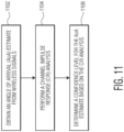
- Fig. 11 is a process flow diagram of a method for wireless communications in accordance with an embodiment of the invention.
- an AoA estimate is obtained from wireless signals.
- a CIR analysis is performed.
- a confidence level for the AoA estimate is determined based on the CIR analysis.
- an embodiment of a computer program product includes a computer useable storage medium to store a computer readable program that, when executed on a computer, causes the computer to perform operations, as described herein.
- the computer-useable or computer-readable medium can be an electronic, magnetic, optical, electromagnetic, infrared, or semiconductor system (or apparatus or device), or a propagation medium.
- Examples of a computer-readable medium include a semiconductor or solid-state memory, magnetic tape, a removable computer diskette, a random access memory (RAM), a read-only memory (ROM), a rigid magnetic disc, and an optical disc.
- Current examples of optical discs include a compact disc with read only memory (CD-ROM), a compact disc with read/write (CD-R/W), a digital video disc (DVD), and a Bluray disc.
Landscapes
- Engineering & Computer Science (AREA)
- Computer Networks & Wireless Communication (AREA)
- Signal Processing (AREA)
- Physics & Mathematics (AREA)
- General Physics & Mathematics (AREA)
- Radar, Positioning & Navigation (AREA)
- Remote Sensing (AREA)
- Power Engineering (AREA)
- Mobile Radio Communication Systems (AREA)
- Position Fixing By Use Of Radio Waves (AREA)
Applications Claiming Priority (1)
| Application Number | Priority Date | Filing Date | Title |
|---|---|---|---|
| US18/208,080 US12587416B2 (en) | 2023-06-09 | 2023-06-09 | System and method for angle of arrival (AoA) estimation |
Publications (1)
| Publication Number | Publication Date |
|---|---|
| EP4481424A1 true EP4481424A1 (fr) | 2024-12-25 |
Family
ID=91376063
Family Applications (1)
| Application Number | Title | Priority Date | Filing Date |
|---|---|---|---|
| EP24179694.5A Pending EP4481424A1 (fr) | 2023-06-09 | 2024-06-03 | Système et procédé d'estimation d'angle d'arrivée (aoa) |
Country Status (3)
| Country | Link |
|---|---|
| US (1) | US12587416B2 (fr) |
| EP (1) | EP4481424A1 (fr) |
| CN (1) | CN119110307A (fr) |
Families Citing this family (1)
| Publication number | Priority date | Publication date | Assignee | Title |
|---|---|---|---|---|
| CN116137952B (zh) * | 2020-07-31 | 2025-11-18 | 瑞典爱立信有限公司 | 用于toa估计的cir峰值阈值控制 |
Citations (3)
| Publication number | Priority date | Publication date | Assignee | Title |
|---|---|---|---|---|
| CA2307532A1 (fr) * | 1999-05-06 | 2000-11-06 | Cell-Loc Inc. | Systeme de localisation sans fil |
| US20220196782A1 (en) * | 2020-12-22 | 2022-06-23 | Samsung Electronics Co., Ltd. | Three-dimensional angle of arrival capability in electronic devices |
| US20230164001A1 (en) * | 2021-11-22 | 2023-05-25 | Samsung Electronics Co., Ltd. | Electronic device and method of estimating channel impulse response |
-
2023
- 2023-06-09 US US18/208,080 patent/US12587416B2/en active Active
-
2024
- 2024-04-22 CN CN202410483793.0A patent/CN119110307A/zh active Pending
- 2024-06-03 EP EP24179694.5A patent/EP4481424A1/fr active Pending
Patent Citations (3)
| Publication number | Priority date | Publication date | Assignee | Title |
|---|---|---|---|---|
| CA2307532A1 (fr) * | 1999-05-06 | 2000-11-06 | Cell-Loc Inc. | Systeme de localisation sans fil |
| US20220196782A1 (en) * | 2020-12-22 | 2022-06-23 | Samsung Electronics Co., Ltd. | Three-dimensional angle of arrival capability in electronic devices |
| US20230164001A1 (en) * | 2021-11-22 | 2023-05-25 | Samsung Electronics Co., Ltd. | Electronic device and method of estimating channel impulse response |
Non-Patent Citations (1)
| Title |
|---|
| ZHONGHAI WANG ET AL: "A New Multi-Antenna Based LOS - NLOS Separation Technique", DIGITAL SIGNAL PROCESSING WORKSHOP AND 5TH IEEE SIGNAL PROCESSING EDUCATION WORKSHOP, 2009. DSP/SPE 2009. IEEE 13TH, IEEE, PISCATAWAY, NJ, USA, 4 January 2009 (2009-01-04), pages 331 - 336, XP031425865, ISBN: 978-1-4244-3677-4 * |
Also Published As
| Publication number | Publication date |
|---|---|
| US20240414026A1 (en) | 2024-12-12 |
| CN119110307A (zh) | 2024-12-10 |
| US12587416B2 (en) | 2026-03-24 |
Similar Documents
| Publication | Publication Date | Title |
|---|---|---|
| US20220334237A1 (en) | Method and apparatus for determining location using phase difference of arrival | |
| US10203397B2 (en) | Methods and apparatus for improving time of arrival determination | |
| KR102416604B1 (ko) | 무선통신 시스템의 정밀 측위 방법 및 장치 | |
| US7574221B2 (en) | Method for estimating jointly time-of-arrival of signals and terminal location | |
| US9084217B2 (en) | Single-site localization via multipath fingerprinting | |
| CN103140772B (zh) | 用于定位通信网络中的至少一个障碍物的方法和设备、相应的计算机程序 | |
| CN102792177B (zh) | 测向方法 | |
| US20180076875A1 (en) | Method and apparatus for non-linear antenna array angle of arrival detection | |
| US20140256352A1 (en) | Method for measuring position of user terminal | |
| EP3550890B1 (fr) | Procédé de reconnaissance de trajet en visibilité directe, et dispositif sans fil | |
| Eleftherakis et al. | SPRING+: Smartphone positioning from a single WiFi access point | |
| CN118524517B (zh) | 一种终端定位方法及相关装置 | |
| Huang et al. | Enhanced LTE TOA/OTDOA estimation with first arriving path detection | |
| CN106535217A (zh) | 基于gdop分析的gsm‑r干扰源融合定位方法 | |
| US12587416B2 (en) | System and method for angle of arrival (AoA) estimation | |
| Gunia et al. | Analysis and design of a MuSiC-based angle of arrival positioning system | |
| EP4145166A1 (fr) | Mesure de positionnement | |
| Brida et al. | An experimental evaluation of AGA algorithm for RSS positioning in GSM networks | |
| Figueroa et al. | Optimal weight scheme for fusion-assisted cooperative multi-monostatic object localization in 6G networks | |
| US20250234331A1 (en) | User equipment localization using digital replica rf maps | |
| Shirai et al. | An Experimental Investigation of the MUSIC-based Wireless Position Location using LCX antenna at 5GHz band | |
| CN115480209B (zh) | 一种多天线uwb的nlos识别方法 | |
| Ruppert et al. | An SDR-Based Evaluation of Maximum Likelihood Estimator and MUSIC Algorithm for TDOA in 5G Campus Networks | |
| Alfiza | Angle-of-Arrival Measurement Techniques for Enhanced Positioning in Beyond 5G Systems | |
| Öktem et al. | Power delay Doppler profile fingerprinting for mobile localization in NLOS |
Legal Events
| Date | Code | Title | Description |
|---|---|---|---|
| PUAI | Public reference made under article 153(3) epc to a published international application that has entered the european phase |
Free format text: ORIGINAL CODE: 0009012 |
|
| STAA | Information on the status of an ep patent application or granted ep patent |
Free format text: STATUS: THE APPLICATION HAS BEEN PUBLISHED |
|
| AK | Designated contracting states |
Kind code of ref document: A1 Designated state(s): AL AT BE BG CH CY CZ DE DK EE ES FI FR GB GR HR HU IE IS IT LI LT LU LV MC ME MK MT NL NO PL PT RO RS SE SI SK SM TR |
|
| STAA | Information on the status of an ep patent application or granted ep patent |
Free format text: STATUS: REQUEST FOR EXAMINATION WAS MADE |
|
| 17P | Request for examination filed |
Effective date: 20250625 |