EP4481852A1 - Positivelektrodenaktivmaterial, positivelektrodenfolie, elektrochemische energiespeichervorrichtung, sekundärbatterie, elektrische vorrichtung und herstellungsverfahren - Google Patents
Positivelektrodenaktivmaterial, positivelektrodenfolie, elektrochemische energiespeichervorrichtung, sekundärbatterie, elektrische vorrichtung und herstellungsverfahren Download PDFInfo
- Publication number
- EP4481852A1 EP4481852A1 EP22959932.9A EP22959932A EP4481852A1 EP 4481852 A1 EP4481852 A1 EP 4481852A1 EP 22959932 A EP22959932 A EP 22959932A EP 4481852 A1 EP4481852 A1 EP 4481852A1
- Authority
- EP
- European Patent Office
- Prior art keywords
- particles
- optionally
- positive electrode
- active material
- electrode active
- Prior art date
- Legal status (The legal status is an assumption and is not a legal conclusion. Google has not performed a legal analysis and makes no representation as to the accuracy of the status listed.)
- Pending
Links
Images


Classifications
-
- H—ELECTRICITY
- H01—ELECTRIC ELEMENTS
- H01M—PROCESSES OR MEANS, e.g. BATTERIES, FOR THE DIRECT CONVERSION OF CHEMICAL ENERGY INTO ELECTRICAL ENERGY
- H01M4/00—Electrodes
- H01M4/02—Electrodes composed of, or comprising, active material
- H01M4/36—Selection of substances as active materials, active masses, active liquids
- H01M4/362—Composites
- H01M4/364—Composites as mixtures
-
- C—CHEMISTRY; METALLURGY
- C01—INORGANIC CHEMISTRY
- C01G—COMPOUNDS CONTAINING METALS NOT COVERED BY SUBCLASSES C01D OR C01F
- C01G53/00—Compounds of nickel
- C01G53/40—Complex oxides containing nickel and at least one other metal element
- C01G53/42—Complex oxides containing nickel and at least one other metal element containing alkali metals, e.g. LiNiO2
- C01G53/44—Complex oxides containing nickel and at least one other metal element containing alkali metals, e.g. LiNiO2 containing manganese
- C01G53/50—Complex oxides containing nickel and at least one other metal element containing alkali metals, e.g. LiNiO2 containing manganese of the type (MnO2)n-, e.g. Li(NixMn1-x)O2 or Li(MyNixMn1-x-y)O2
-
- C—CHEMISTRY; METALLURGY
- C01—INORGANIC CHEMISTRY
- C01G—COMPOUNDS CONTAINING METALS NOT COVERED BY SUBCLASSES C01D OR C01F
- C01G53/00—Compounds of nickel
- C01G53/40—Complex oxides containing nickel and at least one other metal element
- C01G53/42—Complex oxides containing nickel and at least one other metal element containing alkali metals, e.g. LiNiO2
- C01G53/44—Complex oxides containing nickel and at least one other metal element containing alkali metals, e.g. LiNiO2 containing manganese
- C01G53/50—Complex oxides containing nickel and at least one other metal element containing alkali metals, e.g. LiNiO2 containing manganese of the type (MnO2)n-, e.g. Li(NixMn1-x)O2 or Li(MyNixMn1-x-y)O2
- C01G53/502—Complex oxides containing nickel and at least one other metal element containing alkali metals, e.g. LiNiO2 containing manganese of the type (MnO2)n-, e.g. Li(NixMn1-x)O2 or Li(MyNixMn1-x-y)O2 containing lithium and cobalt
- C01G53/504—Complex oxides containing nickel and at least one other metal element containing alkali metals, e.g. LiNiO2 containing manganese of the type (MnO2)n-, e.g. Li(NixMn1-x)O2 or Li(MyNixMn1-x-y)O2 containing lithium and cobalt with the molar ratio of nickel with respect to all the metals other than alkali metals higher than or equal to 0.5, e.g. Li(MzNixCoyMn1-x-y-z)O2 with x ≥ 0.5
-
- C—CHEMISTRY; METALLURGY
- C01—INORGANIC CHEMISTRY
- C01G—COMPOUNDS CONTAINING METALS NOT COVERED BY SUBCLASSES C01D OR C01F
- C01G53/00—Compounds of nickel
- C01G53/40—Complex oxides containing nickel and at least one other metal element
- C01G53/42—Complex oxides containing nickel and at least one other metal element containing alkali metals, e.g. LiNiO2
- C01G53/44—Complex oxides containing nickel and at least one other metal element containing alkali metals, e.g. LiNiO2 containing manganese
- C01G53/50—Complex oxides containing nickel and at least one other metal element containing alkali metals, e.g. LiNiO2 containing manganese of the type (MnO2)n-, e.g. Li(NixMn1-x)O2 or Li(MyNixMn1-x-y)O2
- C01G53/502—Complex oxides containing nickel and at least one other metal element containing alkali metals, e.g. LiNiO2 containing manganese of the type (MnO2)n-, e.g. Li(NixMn1-x)O2 or Li(MyNixMn1-x-y)O2 containing lithium and cobalt
- C01G53/504—Complex oxides containing nickel and at least one other metal element containing alkali metals, e.g. LiNiO2 containing manganese of the type (MnO2)n-, e.g. Li(NixMn1-x)O2 or Li(MyNixMn1-x-y)O2 containing lithium and cobalt with the molar ratio of nickel with respect to all the metals other than alkali metals higher than or equal to 0.5, e.g. Li(MzNixCoyMn1-x-y-z)O2 with x ≥ 0.5
- C01G53/506—Complex oxides containing nickel and at least one other metal element containing alkali metals, e.g. LiNiO2 containing manganese of the type (MnO2)n-, e.g. Li(NixMn1-x)O2 or Li(MyNixMn1-x-y)O2 containing lithium and cobalt with the molar ratio of nickel with respect to all the metals other than alkali metals higher than or equal to 0.5, e.g. Li(MzNixCoyMn1-x-y-z)O2 with x ≥ 0.5 with the molar ratio of nickel with respect to all the metals other than alkali metals higher than or equal to 0.8, e.g. Li(MzNixCoyMn1-x-y-z)O2 with x ≥ 0.8
-
- H—ELECTRICITY
- H01—ELECTRIC ELEMENTS
- H01M—PROCESSES OR MEANS, e.g. BATTERIES, FOR THE DIRECT CONVERSION OF CHEMICAL ENERGY INTO ELECTRICAL ENERGY
- H01M4/00—Electrodes
- H01M4/02—Electrodes composed of, or comprising, active material
- H01M4/04—Processes of manufacture in general
- H01M4/0471—Processes of manufacture in general involving thermal treatment, e.g. firing, sintering, backing particulate active material, thermal decomposition, pyrolysis
-
- H—ELECTRICITY
- H01—ELECTRIC ELEMENTS
- H01M—PROCESSES OR MEANS, e.g. BATTERIES, FOR THE DIRECT CONVERSION OF CHEMICAL ENERGY INTO ELECTRICAL ENERGY
- H01M4/00—Electrodes
- H01M4/02—Electrodes composed of, or comprising, active material
- H01M4/13—Electrodes for accumulators with non-aqueous electrolyte, e.g. for lithium-accumulators; Processes of manufacture thereof
- H01M4/131—Electrodes based on mixed oxides or hydroxides, or on mixtures of oxides or hydroxides, e.g. LiCoOx
-
- H—ELECTRICITY
- H01—ELECTRIC ELEMENTS
- H01M—PROCESSES OR MEANS, e.g. BATTERIES, FOR THE DIRECT CONVERSION OF CHEMICAL ENERGY INTO ELECTRICAL ENERGY
- H01M4/00—Electrodes
- H01M4/02—Electrodes composed of, or comprising, active material
- H01M4/36—Selection of substances as active materials, active masses, active liquids
- H01M4/362—Composites
- H01M4/366—Composites as layered products
-
- H—ELECTRICITY
- H01—ELECTRIC ELEMENTS
- H01M—PROCESSES OR MEANS, e.g. BATTERIES, FOR THE DIRECT CONVERSION OF CHEMICAL ENERGY INTO ELECTRICAL ENERGY
- H01M4/00—Electrodes
- H01M4/02—Electrodes composed of, or comprising, active material
- H01M4/36—Selection of substances as active materials, active masses, active liquids
- H01M4/48—Selection of substances as active materials, active masses, active liquids of inorganic oxides or hydroxides
- H01M4/50—Selection of substances as active materials, active masses, active liquids of inorganic oxides or hydroxides of manganese
- H01M4/505—Selection of substances as active materials, active masses, active liquids of inorganic oxides or hydroxides of manganese of mixed oxides or hydroxides containing manganese for inserting or intercalating light metals, e.g. LiMn2O4 or LiMn2OxFy
-
- H—ELECTRICITY
- H01—ELECTRIC ELEMENTS
- H01M—PROCESSES OR MEANS, e.g. BATTERIES, FOR THE DIRECT CONVERSION OF CHEMICAL ENERGY INTO ELECTRICAL ENERGY
- H01M4/00—Electrodes
- H01M4/02—Electrodes composed of, or comprising, active material
- H01M4/36—Selection of substances as active materials, active masses, active liquids
- H01M4/48—Selection of substances as active materials, active masses, active liquids of inorganic oxides or hydroxides
- H01M4/52—Selection of substances as active materials, active masses, active liquids of inorganic oxides or hydroxides of nickel, cobalt or iron
- H01M4/525—Selection of substances as active materials, active masses, active liquids of inorganic oxides or hydroxides of nickel, cobalt or iron of mixed oxides or hydroxides containing iron, cobalt or nickel for inserting or intercalating light metals, e.g. LiNiO2, LiCoO2 or LiCoOxFy
-
- H—ELECTRICITY
- H01—ELECTRIC ELEMENTS
- H01M—PROCESSES OR MEANS, e.g. BATTERIES, FOR THE DIRECT CONVERSION OF CHEMICAL ENERGY INTO ELECTRICAL ENERGY
- H01M4/00—Electrodes
- H01M4/02—Electrodes composed of, or comprising, active material
- H01M4/62—Selection of inactive substances as ingredients for active masses, e.g. binders, fillers
-
- C—CHEMISTRY; METALLURGY
- C01—INORGANIC CHEMISTRY
- C01P—INDEXING SCHEME RELATING TO STRUCTURAL AND PHYSICAL ASPECTS OF SOLID INORGANIC COMPOUNDS
- C01P2002/00—Crystal-structural characteristics
- C01P2002/50—Solid solutions
- C01P2002/52—Solid solutions containing elements as dopants
-
- C—CHEMISTRY; METALLURGY
- C01—INORGANIC CHEMISTRY
- C01P—INDEXING SCHEME RELATING TO STRUCTURAL AND PHYSICAL ASPECTS OF SOLID INORGANIC COMPOUNDS
- C01P2002/00—Crystal-structural characteristics
- C01P2002/70—Crystal-structural characteristics defined by measured X-ray, neutron or electron diffraction data
- C01P2002/74—Crystal-structural characteristics defined by measured X-ray, neutron or electron diffraction data by peak-intensities or a ratio thereof only
-
- C—CHEMISTRY; METALLURGY
- C01—INORGANIC CHEMISTRY
- C01P—INDEXING SCHEME RELATING TO STRUCTURAL AND PHYSICAL ASPECTS OF SOLID INORGANIC COMPOUNDS
- C01P2004/00—Particle morphology
- C01P2004/54—Particles characterised by their aspect ratio, i.e. the ratio of sizes in the longest to the shortest dimension
-
- C—CHEMISTRY; METALLURGY
- C01—INORGANIC CHEMISTRY
- C01P—INDEXING SCHEME RELATING TO STRUCTURAL AND PHYSICAL ASPECTS OF SOLID INORGANIC COMPOUNDS
- C01P2004/00—Particle morphology
- C01P2004/60—Particles characterised by their size
-
- C—CHEMISTRY; METALLURGY
- C01—INORGANIC CHEMISTRY
- C01P—INDEXING SCHEME RELATING TO STRUCTURAL AND PHYSICAL ASPECTS OF SOLID INORGANIC COMPOUNDS
- C01P2004/00—Particle morphology
- C01P2004/60—Particles characterised by their size
- C01P2004/61—Micrometer sized, i.e. from 1-100 micrometer
-
- C—CHEMISTRY; METALLURGY
- C01—INORGANIC CHEMISTRY
- C01P—INDEXING SCHEME RELATING TO STRUCTURAL AND PHYSICAL ASPECTS OF SOLID INORGANIC COMPOUNDS
- C01P2004/00—Particle morphology
- C01P2004/80—Particles consisting of a mixture of two or more inorganic phases
- C01P2004/82—Particles consisting of a mixture of two or more inorganic phases two phases having the same anion, e.g. both oxidic phases
- C01P2004/84—Particles consisting of a mixture of two or more inorganic phases two phases having the same anion, e.g. both oxidic phases one phase coated with the other
-
- C—CHEMISTRY; METALLURGY
- C01—INORGANIC CHEMISTRY
- C01P—INDEXING SCHEME RELATING TO STRUCTURAL AND PHYSICAL ASPECTS OF SOLID INORGANIC COMPOUNDS
- C01P2006/00—Physical properties of inorganic compounds
- C01P2006/10—Solid density
-
- C—CHEMISTRY; METALLURGY
- C01—INORGANIC CHEMISTRY
- C01P—INDEXING SCHEME RELATING TO STRUCTURAL AND PHYSICAL ASPECTS OF SOLID INORGANIC COMPOUNDS
- C01P2006/00—Physical properties of inorganic compounds
- C01P2006/12—Surface area
-
- H—ELECTRICITY
- H01—ELECTRIC ELEMENTS
- H01M—PROCESSES OR MEANS, e.g. BATTERIES, FOR THE DIRECT CONVERSION OF CHEMICAL ENERGY INTO ELECTRICAL ENERGY
- H01M10/00—Secondary cells; Manufacture thereof
- H01M10/05—Accumulators with non-aqueous electrolyte
- H01M10/052—Li-accumulators
- H01M10/0525—Rocking-chair batteries, i.e. batteries with lithium insertion or intercalation in both electrodes; Lithium-ion batteries
-
- H—ELECTRICITY
- H01—ELECTRIC ELEMENTS
- H01M—PROCESSES OR MEANS, e.g. BATTERIES, FOR THE DIRECT CONVERSION OF CHEMICAL ENERGY INTO ELECTRICAL ENERGY
- H01M4/00—Electrodes
- H01M4/02—Electrodes composed of, or comprising, active material
- H01M2004/021—Physical characteristics, e.g. porosity, surface area
-
- H—ELECTRICITY
- H01—ELECTRIC ELEMENTS
- H01M—PROCESSES OR MEANS, e.g. BATTERIES, FOR THE DIRECT CONVERSION OF CHEMICAL ENERGY INTO ELECTRICAL ENERGY
- H01M4/00—Electrodes
- H01M4/02—Electrodes composed of, or comprising, active material
- H01M2004/026—Electrodes composed of, or comprising, active material characterised by the polarity
- H01M2004/028—Positive electrodes
-
- Y—GENERAL TAGGING OF NEW TECHNOLOGICAL DEVELOPMENTS; GENERAL TAGGING OF CROSS-SECTIONAL TECHNOLOGIES SPANNING OVER SEVERAL SECTIONS OF THE IPC; TECHNICAL SUBJECTS COVERED BY FORMER USPC CROSS-REFERENCE ART COLLECTIONS [XRACs] AND DIGESTS
- Y02—TECHNOLOGIES OR APPLICATIONS FOR MITIGATION OR ADAPTATION AGAINST CLIMATE CHANGE
- Y02E—REDUCTION OF GREENHOUSE GAS [GHG] EMISSIONS, RELATED TO ENERGY GENERATION, TRANSMISSION OR DISTRIBUTION
- Y02E60/00—Enabling technologies; Technologies with a potential or indirect contribution to GHG emissions mitigation
- Y02E60/10—Energy storage using batteries
Definitions
- This application relates to the field of energy technologies and the field of secondary battery technologies, and further relates to a positive electrode active material, a positive electrode plate, an electrochemical energy storage apparatus, a secondary battery, an electric apparatus, and a preparation method.
- High-nickel materials for example, high-nickel ternary materials
- high capacity and low cycle fading have received extensive attention from the industry.
- the current high watt-hour costs of high-nickel materials restrict their promotion and application.
- this application provides a positive electrode active material, a positive electrode plate, an electrochemical energy storage apparatus, a secondary battery, an electric apparatus, and a preparation method.
- the positive electrode active material is a high-nickel positive electrode material having small particles and large particles with a specific structure, and the percentage of the small particles is higher than that of the large particles.
- the positive electrode plate prepared has a high mass-specific capacity and excellent structural stability. Further, at the cell level, the mass energy density and cycle life of the cell can be significantly improved, and side reactions with the electrolyte can be reduced, reducing the gas generation of the cell.
- this application provides a positive electrode active material including particles A and particles B, where molar ratio R Ni/Li of element nickel to element lithium in each of the particles A and the particles B is independently greater than or equal to 0.33.
- the particles A have a monocrystalline or monocrystalline-like structure
- the particles B are secondary particles including a plurality of primary particles, where D v 50 of the particles A is less than D v 50 of the particles B, and a mass percentage of the particles A is greater than or equal to a mass percentage of the particles B.
- D v N denotes a particle size corresponding to a cumulative volume distribution percentage of a material reaching N%, N being a value selected from 0-100.
- conventional high-nickel materials for example, high-nickel ternary materials
- the cracking degree tends to deepen at high voltages, leading to a shorter cycle life.
- the enhanced oxidation activity of the positive electrode during storage makes the positive electrode prone to intensive chemical reactions with the electrolyte, resulting in a decrease in cell life and an increase in gas generation per unit capacity.
- the positive electrode active material includes high-nickel positive electrode materials with different particle sizes, where small particles and large particles are distinguished by D v 50, particles A having a monocrystalline or monocrystalline-like structure are used as the small particles, particles B formed by agglomeration of primary particles are used as the large particles, and the mass percentage of the particles A is also controlled to be higher than that of the particles B.
- the particles A of a special crystal phase structure have a homogeneous phase system or a near homogeneous bulk, and in the process of lithium deintercalation or intercalation of the material, generation of stress is not likely to occur in the material, and it is not likely to cause cracking of the material under stress, which is therefore more conducive to improving the cycling and storage performance of the cell under high-voltage conditions.
- the particles B are formed by agglomeration of primary particles, which is conducive to improving the power performance and compacted density. Through the control of the percentage of the particles A relative to the particles B, the percentage of the particles B is less than that of the particles A, which can reduce the stress caused by the contraction and expansion of the lattice of large particles.
- the particle size of the particles A satisfies 2 ⁇ m ⁇ D v 50 ⁇ 5 ⁇ m
- the particle size of the particles B satisfies 5 ⁇ m ⁇ D v 50 ⁇ 25 ⁇ m.
- the Span value of the particles A is selected from 0.1-3.0; and the Span value of the particles B is selected from 0.1-3.0.
- the particle size of the particles B satisfies 8 ⁇ m ⁇ D v 50 ⁇ 20 ⁇ m.
- the particles B include particles B1 and particles B2, where the particle size of the particles B1 satisfies 5 ⁇ m ⁇ D v 50 ⁇ 10 ⁇ m, and the particle size of the particles B2 satisfies 10 ⁇ m ⁇ D v 50 ⁇ 25 ⁇ m.
- the weight percentage of the particles B1 in the particles B is selected from 50-100%.
- the weight percentage of the particles B2 in the particles B is selected from 0-50%.
- the particles B are further divided into particles B1 and particles B2, so that D v 50 of the particles B1 is less than D v 50 of the particles B2.
- D v 50 of the particles B1 is less than D v 50 of the particles B2.
- a proper control of the percentage of particles with different particle sizes and the broadening coefficient Span can further improve the power performance, prevent overly dense buildup from affecting the infiltration of the electrolyte, and prevent the formation of concentration gradients due to the inability of the electrolyte to come into contact with the internal active materials of the electrode plate, resulting in unfavorable constraints on lithium-ion transport.
- the particles B include particles B 1', particles B2', and particles B3', where the particle size of the particles B1' satisfies 8 ⁇ m ⁇ D v 50 ⁇ 12 ⁇ m, the particle size of the particles B2' satisfies 12 ⁇ m ⁇ D v 50 ⁇ 15 ⁇ m, and the particle size of the particles B3' satisfies 15 ⁇ m ⁇ D v 50 ⁇ 20 ⁇ m.
- the weight percentage of the particles B1' in the particles B is selected from 40-80%.
- the weight percentage of the particles B2' in the particles B is selected from 20-30%.
- the weight percentage of the particles B3' in the particles B is selected from 0-30%.
- the particles B are further divided into particles B 1', particles B2', and particles B3' with increasing D v 50, allowing inclusion of particles in four size grades in the positive electrode active material and finer control over the particle size of the larger-sized particles.
- a proper control of the percentage of the four particles and the broadening coefficient Span can improve the power performance, prevent overly dense buildup from affecting the infiltration of the electrolyte, and prevent the formation of concentration gradients due to the inability of the electrolyte to come into contact with the internal active materials of the electrode plate, resulting in unfavorable constraints on lithium-ion transport.
- the particles A and the particles B each independently include the following combination of elements Ni x Co y M 1-x-y , where x ⁇ 0.4, y >_ 0, (1-x-y) >_ 0, and the element M includes one or both of Mn and Al.
- y > 0; and optionally, 0 ⁇ y ⁇ _ 0.15.
- the particles A and the particles B each independently include a material with a chemical formula Li k-a Q a (Ni x Co y M 1-x-y ) 1-z N z O 2-c X c , where 0.9 ⁇ k ⁇ 1.1, 0 ⁇ a ⁇ 0.2, 0.60 ⁇ x ⁇ 1.00, 0 ⁇ y ⁇ 0.15, 0 ⁇ (1-x-y), 0 ⁇ z ⁇ 0.5, 0 ⁇ c ⁇ 1, the element M includes one or both of Mn and Al, the element Q includes one or more of Na, K, Rb, and Ca, the element N includes one or more of Al, Ti, Zr, Nb, Sr, Sb, Y, Ba, Co, Mn, Mg, W, Si, Mo, P, and C, and the element X includes one or more of B, F, S, and Cl.
- the nickel-lithium molar ratio R Ni/Li in each of the particles A and the particles B is independently greater than or equal to 0.4.
- the nickel-lithium molar ratio R Ni/Li in each of the particles A and the particles B is independently greater than or equal to 0.5.
- the nickel-lithium molar ratio R Ni/Li in each of the particles A and the particles B is independently greater than or equal to 0.6.
- the nickel-lithium molar ratio R Ni/Li in each of the particles A and the particles B is independently greater than or equal to 0.7.
- the nickel-lithium molar ratio R Ni/Li in each of the particles A and the particles B is independently greater than or equal to 0.8.
- the nickel-lithium molar ratio R Ni/Li in the particles A is selected from 0.7-1.0.
- the nickel-lithium molar ratio R Ni/Li in the particles B is selected from 0.8-1.0.
- the nickel-lithium molar ratio R Ni/Li in the particles B is selected from 0.8-0.96.
- nickel-rich positive electrode materials for example, nickel-rich ternary positive electrode materials
- the changes in unit cell parameters can induce internal stress within the material.
- the degree of lithium deintercalation or intercalation in nickel-rich materials is further increased.
- the positive electrode active material may be a conventional nickel-rich ternary positive electrode material.
- doping of element N may be further introduced into the ternary positive electrode active material, which can reduce the degree of lattice change of the material and play a role in stabilizing the lattice, thereby improving the cycling performance of the nickel-rich ternary material.
- true densities of the particles A and the particles B each are independently greater than 4.0 g/cc.
- the true densities of the particles A and the particles B each are independently selected from 4.0-4.8 g/cc.
- the true density of the particles A each is independently selected from 4.6-4.8 g/cc.
- the true density of the particles B each is independently selected from 4.5-4.8 g/cc.
- the true density is one of the main factors determining the compacted density of the positive electrode material.
- Proper control of the true densities of the particles A and the particles B is favorable to increase the volumetric specific capacity and the energy density of the positive electrode plate, so as to better improve the cell performance while alleviating the problem of material cracking under high voltage.
- a closer particle arrangement of the material indicates a higher theoretically achievable volumetric specific capacity of the positive electrode material.
- the particles A and the particles B each independently include a body structure and an oxide layer enveloping at least a portion of the surface of the body structure; where, the body structure includes a material with a chemical formula Li k1-a1 Q a1 (Ni x1 Co y1 M 1-X1-y1 ) 1-z1 N z1 O 2 , where 0.9 ⁇ k1 ⁇ 1.1, 0 ⁇ a1 ⁇ 0.20, 0.40 ⁇ x1 ⁇ 1.00, 0 ⁇ y1 ⁇ 0.15, 0 ⁇ (1-xl-yl), 0 ⁇ z1 ⁇ 0.5, the element Q includes one or more of Na, K, Rb, and Ca, the element M includes one or both of Mn and Al, and the element N includes one or more of Al, Ti, Zr, Nb, Sr, Sb, Y, Ba, Co, Mn, Mg, Si, P, Mo, C, and W.
- the element Q includes one or more of Na
- the element N includes one or more of Al, Ti, Zr, Nb, Sr, Sb, Y, Mg, and W.
- the oxide layer includes a material with a chemical formula Li k2-a2 Q' a2 (Ni x2 Co y2 M' 1-x2-y2 ) 1-z2 N' z2 O 2-c2 X c2 , where 0 ⁇ a2 ⁇ 0.20, 0.40 ⁇ x2 ⁇ 1.00, 0 ⁇ y2 ⁇ 0.15, 0 ⁇ (1-x2-y2), 0 ⁇ z2 ⁇ 0.5, 0 ⁇ c2 ⁇ 1, the element Q' includes one or more of Na, K, Rb, and Ca, the element M' includes one or both of Mn and Al, the element N' includes one or more of Al, Ti, Zr, Nb, Sr, Sb, Y, Ba, Co, Mn, Mg, W, Mo, Si, C, and P, and the element X includes one or more of B, Cl, S, and F.
- 0.92 ⁇ k2 ⁇ 1.08; optionally, 0.95 ⁇ k2 ⁇ 1.05; optionally, 0.96 ⁇ k2 ⁇ 1.04; optionally, 0.98 ⁇ k2 ⁇ 1.02; optionally, 0.99 ⁇ k2 ⁇ 1.01; and optionally, k2 is equal to 1.
- Q' a2 Ni x2 Co y2 M' 1-x-y is the same as Q a1 Ni x1 Co y1 M 1-x1-y1 .
- the element N' includes one or more of Al, Ti, Zr, Sr, Sb, Mo, Nb, Mg, Y, and W.
- the body structure of the positive electrode active material can be doped with the element Q' (for example, Na, K, Rb, and Ca), thereby increasing the lithium ion diffusion coefficient and reducing the lithium-nickel mixing. It is also possible to coat the surface of the positive electrode active material to form an oxide layer doped with a specific element N' on the surface of the particles, which can reduce the reactivity of the surface of the material with the electrolyte, reduce the release of oxygen from the material, improve the structural stability of the active material, improve the ionic conductivity, and also increase the capacity of the material.
- the element Q' for example, Na, K, Rb, and Ca
- the oxide layer is doped with elements such as Zr, Al, Mg, W, Mo, Co, Sr, Sb, and Nb, where the elements such as Mg, Ti, Al, and Mo can reduce the amount of lattice deformation of the material during charge-discharge cycles, thereby improving the structural stability of the material.
- the oxide layer can reduce the amount of lattice deformation of the material during charge-discharge cycles, thereby improving the structural stability of the material.
- the combination of material particle size design with material structural design it is also possible to achieve higher specific capacity for the material and reduce the degree of side reactions and phase transitions between the positive electrode material and the electrolyte, enabling the battery to have a lower watt-hour cost and a longer cycle life.
- the material without a coating layer is likely to have a large number of side reactions with the electrolyte at the interface, resulting in the oxidation of the electrolyte and the generation of gases such as carbon dioxide and oxygen. Additionally, without a coating layer, the layered structure on the surface of the positive electrode active material is more prone to transforming into a rock-salt structure, resulting in the loss of chemical reactivity on the surface of the material.
- the thickness of the oxide layer is 0-100 nm.
- the thickness of the oxide layer is 1-100 nm.
- the thickness of the oxide layer is 1-20 nm.
- the mass percentage of the oxide layer relative to the body structure is 0.01-5%.
- the mass percentage of the oxide layer relative to the body structure is 0.05-4%.
- the mass percentage of the element N in the oxide layer in the positive electrode active material is 0.01-4%.
- the mass percentage of the element N in the oxide layer in the positive electrode active material is 0.05-4%.
- the amount of the surface oxide layer such as the thickness of the oxide layer, the mass percentage of the oxide layer, the doping amount of the element N, and other parameters, it is possible to better achieve the foregoing doping and coating purposes, better regulate the chemical reactivity and structural stability of the material, better combine the material particle size design and the material structural design, give the material a higher specific capacity, and reduce the degree of side reactions and phase transitions between the positive electrode material and the electrolyte, enabling the battery to have a lower watt-hour cost and a longer cycle life.
- an average specific surface area value of the positive electrode active material is 0.3-1.5 cm 2 /g.
- the free lithium content in the positive electrode active material is less than 3000 ppm in mass ratio.
- the free lithium (for example, lithium carbonate and lithium hydroxide) content in the positive electrode active material can avoid excessive gas generation during cycling under high-voltage conditions. If the free lithium content is high, acid-base neutralization reactions occur between the free lithium and hydrofluoric acid generated by the decomposition of the electrolyte during cycling under the high-voltage conditions, and a large amount of gas is generated, leading to cell swelling and pouch bulging, which is prone to cell safety accidents.
- the free lithium content for example, lithium carbonate and lithium hydroxide
- the ratio I003/I104 of the I003 grain content to the I104 grain content in the positive electrode active material is greater than or equal to 1.2 and is measured as a ratio of areas of characteristic peaks of I003 crystal plane to I104 crystal plane in an XRD pattern.
- I003/I104 is selected from 1.2-2.
- I003/I104 is selected from 1.3-2.
- I003/I104 is selected from 1.3-1.6.
- the degree of lithium-nickel mixing can be better controlled, preventing reduction of the reversible capacity and reduction of the diffusion coefficients of lithium ions resulted from element nickel in an excessive amount occupying lattice sites for element lithium.
- the particles B in the particles B, at least some of the primary particles are in directional arrangement along the radial direction.
- a specific directional arrangement of the primary particles can be made along the radial direction, thereby inhibiting the contraction and expansion that may occur under high voltages and avoiding the increase of internal stresses, better preventing the material from breakage under high voltages, and improving the cycling performance.
- a higher degree of directional arrangement along the radial direction indicates a lower degree of non-directional random arrangement, with more significant improvement in effectiveness.
- this application provides a positive electrode plate including a positive electrode current collector and a positive electrode active material layer disposed on at least one surface of the positive electrode current collector, the positive electrode active material layer including the positive electrode active material according to the first aspect of this application.
- the positive electrode active material according to the first aspect of this application can be used to prepare a positive electrode plate with high nickel content.
- the particle size and content design of the positive electrode active material can be utilized to prevent the material from cracking under high-voltage conditions and improve the cycling and storage performance of the cell under the high-voltage conditions.
- the design of the doping and/or the coating structure can be utilized to regulate the chemical reactivity and the structural stability of the material, which can achieve a higher specific capacity for the material and reduce the degree of side reactions and phase transitions between the positive electrode material and the electrolyte, enabling the battery to have a lower watt-hour cost and a longer cycle life.
- the compacted density of the positive electrode plate is 3.3-3.7 g/cm 3 .
- controlling the positive electrode plate at a more suitable compacted density can better prevent the material from cracking under the high-voltage conditions while giving the electrode plate better specific capacity and energy density.
- the compacted density of the positive electrode plate is also constrained by the true densities of the particles A and particles B contained therein.
- An increase of the compacted density of the electrode plate can increase the volumetric specific capacity of the material, so that the cell in a smaller volume has a longer service life.
- this application provides an electrochemical energy storage apparatus including the positive electrode plate according to the second aspect, a negative electrode plate, and a separator, where the separator is disposed between the positive electrode plate and the negative electrode plate.
- this application provides a secondary battery including at least one of the positive electrode plate according to the second aspect of this application and the electrochemical energy storage apparatus according to the third aspect of this application.
- this application provides an electric apparatus including at least one of the positive electrode plate according to the second aspect of this application, the electrochemical energy storage apparatus according to the third aspect of this application, and the secondary battery according to the fourth aspect of this application.
- the positive electrode active material according to the first aspect of this application can be used to prepare a positive electrode plate with high nickel content and further prepare an electrochemical energy storage apparatus, a secondary battery, and an electric apparatus.
- the particle size and content design of the positive electrode active material can be utilized to prevent the material from cracking under high-voltage conditions and improve the cycling and storage performance of the cell under the high-voltage conditions.
- the design of the doping and/or the coating structure can be utilized to regulate the chemical reactivity and the structural stability of the material, which can achieve a higher specific capacity for the material and reduce the degree of side reactions and phase transitions between the positive electrode material and the electrolyte, enabling the battery to have a lower watt-hour cost and a longer cycle life.
- a preparation method of positive electrode active material including the following step: preparing the positive electrode active material by mixing the particles A and the particles B at a preset mass ratio, where the particles A and particles B are as defined in the first aspect of this application.
- the particles A are prepared by a method including the following steps: mixing lithium hydroxide, nickel-cobalt-M precursor material Ni x Co y M 1-x-y (OH) 2 , an optional Q additive, and an optional N additive for primary sintering in the presence of oxygen and at temperature T1; and optionally, adding at least one of an X additive and the N additive to the primary sintered product for mixing and secondary sintering in the presence of oxygen.
- the particles B are prepared by a method including the following steps: mixing lithium hydroxide, nickel-cobalt-M precursor material Ni x Co y M 1-x-y (OH) 2 , an optional Q additive, and an optional N additive for primary sintering in the presence of oxygen and at temperature T2; and optionally, adding at least one of an X additive and the N additive to the primary sintered product for mixing and secondary sintering in the presence of oxygen.
- the Q additive, N additive, and X additive are an additive containing element Q, an additive containing element N, and an additive containing element X, respectively; and x, y, element M, element Q, element X, and element N are as defined in the first aspect of this application.
- the temperature T1 is higher than the temperature T2.
- the primary sintering temperature is 700-950°C, optionally 750-900°C, and the secondary sintering temperature is 300-600°C, optionally 350-550°C.
- the primary sintering temperature is 700-900°C, optionally 750-850°C
- the secondary sintering temperature is 300-600°C, optionally 350-550°C.
- a stepwise sintering method can be used, where firstly a body structure is formed by sintering a precursor for the body structure in an oxidizing atmosphere at a higher temperature (for example, 700-950°C for particles A, and for another example, 700-900°C for particles B), and then an oxide layer is formed by mixing and sintering the body structure and a coating layer additive in an oxidizing atmosphere at a lower temperature (for example, 300-600°C), to prepare the particles A or particles B with a coating layer.
- a higher temperature for example, 700-950°C for particles A, and for another example, 700-900°C for particles B
- an oxide layer is formed by mixing and sintering the body structure and a coating layer additive in an oxidizing atmosphere at a lower temperature (for example, 300-600°C)
- large-sized monocrystalline or monocrystalline-like particles can be prepared with full bond of the granules at a relatively high primary sintering temperature (T1)
- small-sized secondary particles can be prepared at a relatively low primary sintering temperature (T2), where fine granules in the secondary particles are not bonded or only partially bonded.
- Ranges disclosed in this application are defined in the form of lower and upper limits.
- a given range is defined by one lower limit and one upper limit selected, where the selected lower and upper limits define boundaries of that particular range. Ranges defined in this method may or may not include end values, and any combinations may be used, meaning any lower limit may be combined with any upper limit to form a range. For example, if ranges of 60-120 and 80-110 are provided for a specific parameter, it is understood that ranges of 60-110 and 80-120 can also be envisioned. In addition, if minimum values of a range are given as 1 and 2, and maximum values of the range are given as 3, 4, and 5, the following ranges can all be envisioned: 1-3, 1-4, 1-5, 2-3, 2-4, and 2-5.
- a value range of "a-b” is a short representation of any combination of real numbers between a and b, where both a and b are real numbers.
- a value range of "0-5" means that all real numbers in the range of "0-5" are listed herein, and "0-5" is just a short representation of a combination of these values.
- a parameter expressed as an integer greater than or equal to 2 is equivalent to disclosure that the parameter is, for example, an integer among 2, 3, 4, 5, 6, 7, 8, 9, 10, 11, 12, and so on.
- a method including steps (a) and (b) indicates that the method may include steps (a) and (b) performed in order or may include steps (b) and (a) performed in order.
- the foregoing method may further include step (c), which indicates that step (c) may be added to the method in any ordinal position, for example, the method may include steps (a), (b), and (c), steps (a), (c), and (b), steps (c), (a), and (b), or the like.
- the term "or” is inclusive.
- the phrase “A or B” means “A, B, or both A and B”.
- any one of the following conditions satisfies the condition "A or B”: A is true (or present) and B is false (or not present); A is false (or not present) and B is true (or present); or both A and B are true (or present).
- room temperature generally refers to 4-35°C, and preferably 20°C ⁇ 5°C. In some embodiments of this application, the room temperature refers to 20-30°C.
- the masses or weights of the relevant components mentioned in the specification of the embodiments of this application can not only refer to the content of each component, but also indicate the proportional relation between the masses or weights of the components. Therefore, any content of the relevant components scaled up or down in accordance with the specification of the embodiments of this application falls within the scope of this application. Further, the mass or weight described in the specification of the embodiments of this application may be in ⁇ g, mg, g, kg, and other units of mass or weight known in the chemical field.
- high-nickel materials for example, high-nickel ternary materials
- high capacity and low cycle fading have received extensive attention from the industry.
- the current high watt-hour costs of high-nickel materials restrict their promotion and application.
- One of the effective means to reduce the watt-hour cost of a material is to improve the mass energy density of the material.
- the common ways to improve the mass energy density of high-nickel materials mainly include increasing the charge/discharge voltage and increasing the nickel content in the positive electrode material. Due to high prices of positive electrode raw materials, increasing the charge/discharge voltage of a material has become the most attractive way to increase the mass energy density of the material.
- the degree of material contraction and expansion intensifies, making the material prone to cracking, and side reactions between the positive electrode at the fresh interface generated by the cracking and the electrolyte result in the deterioration of the cell performance.
- the positive electrode is more oxidizing and is prone to oxidizing the organic solvents in the electrolyte to generate gases such as carbon dioxide and oxygen, resulting in an increase in the gas generation of the cell.
- high-voltage conditions refer to a voltage greater than or equal to 4.3 V, unless otherwise specified.
- this application provides a positive electrode active material including particles A and particles B, where molar ratio of element nickel to element lithium (which can be denoted as a nickel-lithium molar ratio R Ni/Li ) in each of the particles A and the particles B is independently greater than or equal to 0.33.
- the particles A have a monocrystalline or monocrystalline-like structure
- the particles B are secondary particles including a plurality of primary particles, where D v 50 of the particles A is less than D v 50 of the particles B, and a mass percentage of the particles A is greater than or equal to a mass percentage of the particles B.
- D v N denotes a particle size corresponding to a cumulative volume distribution percentage of a material reaching N%, N being a value selected from 0-100.
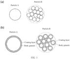
- FIG. 1(a) For structures of the particles A and the particles B in the foregoing positive electrode active material, refer to FIG. 1(a) .
- nickel-rich and “high nickel” have the same meaning and can be used interchangeably to refer to a higher ratio of nickel in a positive electrode active material.
- the molar ratio of nickel, cobalt, and manganese therein is 80:10:10.
- Increasing the nickel content in the positive electrode active material is favorable for increasing the energy density, which can improve the battery capacity.
- the nickel content can be characterized by a molar ratio of element nickel to element lithium.
- the molar ratio can be referred to as the nickel-lithium molar ratio and can be recorded as R Ni/Li .
- each occurrence of R Ni/Li may be independently greater than or equal to 0.33, further, it may be independently greater than or equal to 0.4, and furthermore, it may be independently greater than or equal to 0.5, greater than or equal to 0.6, greater than or equal to 0.7, and greater than or equal to 0.8.
- the nickel-lithium molar ratio R Ni/Li may further be selected from any one of the following values or a range defined by any two of the following values: 0.33, 1/3, 0.4, 0.45, 0.5, 0.55, 0.6, 0.65, 0.7, 0.75, 0.8, 0.02, 0.05, 0.9, 0.95, 1, and the like.
- the nickel-lithium molar ratio R Ni/Li may further be selected from any one of the following value ranges (any value endpoint here may be independently included or excluded): 0.4-1, 0.5-1, 0.6-1, 0.7-1, 0.8-1, 0.8-0.96, and the like.
- the volume cumulative distribution particle size D y N (where N denotes any value selected from 0-100) may be used to characterize the particle size of the material, referring to the particle size of the material corresponding to a cumulative volume distribution percentage of the material reaching N%, with the volume percentage of particle size less than or equal to D v N being N%.
- D v N can be obtained from the volume cumulative distribution curve of the material particle size, and unless otherwise specified, the volume cumulative distribution curve is cumulative from zero on the smaller particle size side.
- D v 99 refers to a particle size when the cumulative volume distribution percentage of the material reaches 99%
- D v 90 refers to a particle size when the cumulative volume distribution percentage of the material reaches 90%
- D v 50 refers to a particle size when the cumulative volume distribution percentage of the material reaches 50%
- D v 10 refers to a particle size when the cumulative volume distribution percentage of the material reaches 10%.
- D v 50 for example, means that the particle size of particles taking account of 50% of the material volume is less than or equal to D v 50, and the particle size of particles taking account of 50% of the material volume is greater than D v 50.
- D v 90 for example, means that the particle size of particles taking account of 90% of the material volume is less than or equal to D v 90, and the particle size of particles taking account of 10% of the material volume is greater than D v 90.
- D v 10 for example, means that the particle size of particles taking account of 10% of the material volume is less than or equal to D v 10, and the particle size of particles taking account of 90% of the material volume is greater than D v 10.
- D v 99, D v 90, D v 50, and D v 10 can be determined using instruments and methods well-known in the art.
- D v 99, D v 90, D v 50, and D v 10 can be easily measured in accordance with a particle size distribution laser diffraction method in GB/T 19077-2016 by using a laser particle size analyzer, for example, a laser particle size analyzer of Mastersizer 2000E from Malvern Instruments Ltd. of UK and the LS-909 laser particle size analyzer (Omec).
- a laser particle size analyzer for example, a laser particle size analyzer of Mastersizer 2000E from Malvern Instruments Ltd. of UK and the LS-909 laser particle size analyzer (Omec).
- monocrystalline-like crystals typically refer to primary particles with sizes greater than 1 ⁇ m but with some degree of agglomeration; and monocrystalline crystals typically refer to primary particles with sizes greater than 1 ⁇ m and no significant agglomeration.
- Primary particle and “secondary particle” are well-known terms in the art.
- Primary particle refers to a monocrystalline grain.
- Secondary particle refers to a particle in an agglomerated state formed by the aggregation of two or more primary particles. The primary particles and the secondary particles can be easily distinguished through SEM images taken using a scanning electron microscope.
- high-nickel materials for example, high-nickel ternary materials
- the cracking degree tends to deepen at high voltages, leading to a decrease in cycle life.
- the enhanced oxidation activity of the positive electrode during storage makes the positive electrode prone to intensive chemical reactions with the electrolyte, resulting in a decrease in cell life and an increase in gas generation per unit capacity.
- the positive electrode active material includes high nickel positive electrode materials with different particle sizes, where small particles and large particles are distinguished by D v 50, particles A having a monocrystalline or monocrystalline-like structure are used as the small particles, particles B formed by agglomeration of primary particles are used as the large particles, and the mass percentage of the particles A is also controlled to be higher than that of the particles B.
- the particles A of a special crystal phase structure have a homogeneous phase system or a near homogeneous bulk, and in the process of lithium deintercalation or intercalation of the material, generation of stress is not likely to occur in the material, and it is not likely to cause cracking of the material under stress, which is therefore more conducive to improving the cycling and storage performance of the cell under high-voltage conditions.
- the particles B are formed by agglomeration of primary particles, which is conducive to improving the power performance and compacted density.
- the percentage of the particles B is less than that of the particles A, which can reduce the stress caused by the contraction and expansion of the lattice of large particles. This helps to prevent the cracking of the positive electrode material under the high-voltage conditions, avoids the formation of new interfaces due to the cracking of the material, and further avoids deterioration of the cell performance and increase in gas generation due to side reactions between the new interfaces and the electrolyte, thus enhancing the cycling stability under the high-voltage conditions and extending the service life of the cell.
- an increase in the percentage of the small-sized particles A is also conducive to increasing the capacity retention rate of the cell after storage and extending the storage calendar life of the material.
- use of the small-sized particles A in a pure monocrystalline system can significantly reduce the compacted density of the electrode plate using the material and the power performance of the cell.
- An increase of the compacted density of the electrode plate can increase the volumetric specific capacity of the material, so that the cell in a smaller volume has a longer service life.
- the particle size of the particles A satisfies 2 ⁇ m ⁇ D v 50 ⁇ 5 ⁇ m
- D v 50 of the particles A may further be selected from any one of the following particle sizes or a range defined by any two of the following particle sizes: 2 ⁇ m, 2.5 ⁇ m, 3 ⁇ m, 3.5 ⁇ m, 4 ⁇ m, 4.5 ⁇ m, 5 ⁇ m, and the like.
- the particle size of the particles B satisfies 5 ⁇ m ⁇ D v 50 ⁇ 25 ⁇ m
- D v 50 of the particles B may further be selected from any one of the following particle sizes or a range defined by any two of the following particle sizes: 5.1 ⁇ m, 5.2 ⁇ m, 5.3 ⁇ m, 5.4 ⁇ m, 5.5 ⁇ m, 6 ⁇ m, 6.5 ⁇ m, 7 ⁇ m, 7.5 ⁇ m, 8 ⁇ m, 8.5 ⁇ m, 9 ⁇ m, 9.5 ⁇ m, 10 ⁇ m, 10.5 ⁇ m, 11 ⁇ m, 11.5 ⁇ m, 12 ⁇ m, 12.5 ⁇ m, 13 ⁇ m, 13.5 ⁇ m, 14 ⁇ m, 14.5 ⁇ m, 15 ⁇ m, 15.5 ⁇ m, 16 ⁇ m, 16.5 ⁇ m, 17 ⁇ m, 17.5 ⁇ m, 18 ⁇ m, 18.5 ⁇ m, 19 ⁇ m, 19.5 ⁇ m, 20
- the particle size of the particles A satisfies 2 ⁇ m ⁇ D v 50 ⁇ 5 ⁇ m
- the particle size of the particles B satisfies 5 ⁇ m ⁇ D v 50 ⁇ 25 ⁇ m.
- the broadening coefficient Span (D v 90-D v 10)/D v 50 for the material of the multi-particle system is also defined.
- the broadening coefficient Span may indicate the degree of dispersion of the particle sizes, and a larger broadening coefficient Span indicates a broader particle distribution of the material in terms of distribution.
- the Span value of the particles A is greater than the Span value of the particles B.
- the Span value of the particles A is selected from 0.1-3.0, and may further be selected from 0.1-2.0, with non-limiting examples such as 0.1, 0.15, 0.2, 0.25, 0.3, 0.35, 0.4, 0.45, 0.5, 0.55, 0.6, 0.65, 0.7, 0.75, 0.8, 0.85, 0.9, 0.95, 1.0, 1.05, 1.1, 1.15, 1.2, 1.25, 1.3, 1.35, 1.4, 1.45, 1.5, 1.55, 1.6, 1.65, 1.7, 1.75, 1.8, 1.85, 1.9, 1.95, 2.0, 2.1, 2.2, 2.3, 2.4, 2.5, 2.6, 2.7, 2.8, and 2.9.
- the Span value of the particles B is selected from 0.1-3.0, may further be selected from 0.1-2.0, and may furthermore be selected from 1.1-2.0, with non-limiting examples such as 0.1, 0.15, 0.2, 0.25, 0.3, 0.35, 0.4, 0.45, 0.5, 0.55, 0.6, 0.65, 0.7, 0.75, 0.8, 0.85 0.9, 0.95, 1.0, 1.05, 1.1, 1.15, 1.2, 1.25, 1.3, 1.35, 1.4, 1.45, 1.5, 1.55, 1.6, 1.65, 1.7, 1.75, 1.8, 1.85, 1.9, 1.95, 2.0, 2.1, 2.2, 2.3, 2.4, 2.5, 2.6, 2.7, 2.8, and 2.
- the Span value of the particles A is selected from 0.1-2.0; and the Span value of the particles B is selected from 0.1-2.0.
- the particle size of the particles B satisfies 8 ⁇ m ⁇ D v 50 ⁇ 20 ⁇ m.
- the particles B include particles B1 and particles B2, and D v 50 of the particles B1 is less than D v 50 of the particles B2.
- the particle size of the particles B1 satisfies 5 ⁇ m ⁇ D v 50 ⁇ 10 ⁇ m
- the particle size of the particles B2 satisfies 10 ⁇ m ⁇ D v 50 ⁇ 25 ⁇ m.
- the particle size of the particles B1 satisfies 5 ⁇ m ⁇ D v 50 ⁇ 10 ⁇ m
- D v 50 of the particles B1 may further be selected from any one of the following particle sizes or a range defined by any two of the following particle sizes: 5.1 ⁇ m, 5.2 ⁇ m, 5.3 ⁇ m, 5.4 ⁇ m, 5.5 ⁇ m, 6 ⁇ m, 6.5 ⁇ m, 7 ⁇ m 7.5 ⁇ m, 8 ⁇ m, 8.5 ⁇ m, 9 ⁇ m, 9.5 ⁇ m, 10 ⁇ m, and the like.
- the particle size of the particles B2 satisfies 10 ⁇ m ⁇ D v 50 ⁇ 25 ⁇ m
- D v 50 of the particles B2 may further be selected from any one of the following particle sizes or a range defined by any two of the following particle sizes: 10.1 ⁇ m, 10.2 ⁇ m, 10.3 ⁇ m, 10.4 ⁇ m, 10.5 ⁇ m, 11 ⁇ m, 11.5 ⁇ m, 12 ⁇ m, 12.5 ⁇ m, 13 ⁇ m, 13.5 ⁇ m, 14 ⁇ m, 14.5 ⁇ m, 15 ⁇ m, 15.5 ⁇ m, 16 ⁇ m, 16.5 ⁇ m, 17 ⁇ m, 17.5 ⁇ m, 18 ⁇ m, 18.5 ⁇ m, 19 ⁇ m, 19.5 ⁇ m, 20 ⁇ m, 20.5 ⁇ m, 21 ⁇ m, 21.5 ⁇ m, 22 ⁇ m, 22.5 ⁇ m, 23 ⁇ m, 23.5 ⁇ m, 24 ⁇ m, 24.5 ⁇ m,
- the weight percentage of the particles B1 in the particles B may be selected from 50-100%, and may further be selected from any one of the following percentages or a range defined by any two of the following percentages: 50%, 55%, 60%, 65%, 70%, 75%, 80%, 85%, 90%, 95%, and the like.
- the weight percentage of the particles B2 in the particles B may be selected from 0-50%, and may further be selected from any one of the following percentages or a range defined by any two of the following percentages: 5%, 10%, 15%, 20%, 25%, 30%, 35%, 40%, 45%, 50%, and the like.
- the Span value of the particles A may be selected from 0.1-2.0, with non-limiting examples such as 0.1, 0.15, 0.2, 0.25, 0.3, 0.35, 0.4, 0.45, 0.5, 0.55, 0.6, 0.65, 0.7, 0.75, 0.8, 0.85, 0.9, 0.95, 1.0, 1.05, 1.1, 1.15, 1.2, 1.25, 1.3, 1.35, 1.4, 1.45, 1.5, 1.55, 1.6, 1.65, 1.7, 1.75, 1.8, 1.85, 1.9, 1.95, 2.0, and the like.
- the Span value of the particles B1 may be selected from 0.1-2.0, with non-limiting examples such as 0.1, 0.15, 0.2, 0.25, 0.3, 0.35, 0.4, 0.45, 0.5, 0.55, 0.6, 0.65, 0.7, 0.75, 0.8, 0.85, 0.9, 0.95, 1.0, 1.05, 1.1, 1.15, 1.2, 1.25, 1.3, 1.35, 1.4, 1.45, 1.5, 1.55, 1.6, 1.65, 1.7, 1.75, 1.8, 1.85, 1.9, 1.95, 2.0, and the like.
- the Span value of the particles B2 may be selected from 0.1-2.0, with non-limiting examples such as 0.1, 0.15, 0.2, 0.25, 0.3, 0.35, 0.4, 0.45, 0.5, 0.55, 0.6, 0.65, 0.7, 0.75, 0.8, 0.85, 0.9, 0.95, 1.0, 1.05, 1.1, 1.15, 1.2, 1.25, 1.3, 1.35, 1.4, 1.45, 1.5, 1.55, 1.6, 1.65, 1.7, 1.75, 1.8, 1.85, 1.9, 1.95, 2.0, and the like.
- the particles B are further divided into particles B1 and particles B2, so that D v 50 of the particles B1 is smaller than D v 50 of the particles B2.
- D v 50 of the particles B1 is smaller than D v 50 of the particles B2.
- a proper control of the percentage of particles with different particle sizes and the broadening coefficient Span can further improve the power performance, prevent overly dense buildup from affecting the infiltration of the electrolyte, and prevent the formation of concentration gradients due to the inability of the electrolyte to come into contact with the internal active materials of the electrode plate, resulting in unfavorable constraints on lithium-ion transport.
- the particles B include particles B1', particles B2', and particles B3', and D v 50 of the particles Bl', particles B2', and particles B3' sequentially increases.
- the particle size of the particles B1' satisfies 8 ⁇ m ⁇ D v 50 ⁇ 12 ⁇ m
- the particle size of the particles B2' satisfies 12 ⁇ m ⁇ D v 50 ⁇ 15 ⁇ m
- the particle size of the particles B3' satisfies 15 ⁇ m ⁇ D v 50 ⁇ 20 ⁇ m.
- the particle size of the particles B1' satisfies 8 ⁇ m ⁇ D v 50 ⁇ 12 ⁇ m
- D v 50 of the particles B1 may further be selected from any one of the following particle sizes or a range defined by any two of the following particle sizes: 8.1 ⁇ m, 8.2 ⁇ m, 8.3 ⁇ m, 8.4 ⁇ m, 8.5 ⁇ m, 9 ⁇ m, 9.5 ⁇ m, 10 ⁇ m, 10.5 ⁇ m, 11 ⁇ m, 11.5 ⁇ m, 12 ⁇ m, and the like.
- the particle size of the particles B2' satisfies 12 ⁇ m ⁇ D v 50 ⁇ 15 ⁇ m
- D v 50 of the particles B2 may further be selected from any one of the following particle sizes or a range defined by any two of the following particle sizes: 12.1 ⁇ m, 12.2 ⁇ m, 12.3 ⁇ m, 12.4 ⁇ m, 12.5 ⁇ m, 13 ⁇ m, 13.5 ⁇ m, 14 ⁇ m, 14.5 ⁇ m, 15 ⁇ m, and the like.
- the particle size of the particles B3' satisfies 15 ⁇ m ⁇ D v 50 ⁇ 20 ⁇ m
- D v 50 of the particles B2 may further be selected from any one of the following particle sizes or a range defined by any two of the following particle sizes: 15.1 ⁇ m, 15.2 ⁇ m, 15.3 ⁇ m, 15.4 ⁇ m, 15.5 ⁇ m, 16 ⁇ m, 16.5 ⁇ m, 17 ⁇ m, 17.5 ⁇ m, 18 ⁇ m, 18.5 ⁇ m, 19 ⁇ m, 19.5 ⁇ m, 20 ⁇ m, and the like.
- the weight percentage of the particles B1' in the particles B is selected from 40-80%, and may further be selected from any one of the following percentages or a range defined by any two of the following percentages: 40%, 45%, 50%, 55%, 60%, 65%, 70%, 75%, 80%, and the like.
- the weight percentage of the particles B2' in the particles B is selected from 20-30%, and may further be selected from any one of the following percentages or a range defined by any two of the following percentages: 20%, 21%, 22%, 23%, 24%, 25%, 26%, 27%, 8%, 9%, 30%, and the like.
- the weight percentage of the particles B3' in the particles B is selected from 0-30%, and may further be selected from any one of the following percentages or a range defined by any two of the following percentages: 2%, 4%, 5%, 6%, 8%, 10%, 12%, 15%, 16%, 18%, 20%, 21%, 22%, 23%, 24%, 25%, 26%, 27%, 8%, 9%, 30%, and the like.
- the Span value of the particles A may be selected from 0.1-2.0, with non-limiting examples such as 0.1, 0.15, 0.2, 0.25, 0.3, 0.35, 0.4, 0.45, 0.5, 0.55, 0.6, 0.65, 0.7, 0.75, 0.8, 0.85, 0.9, 0.95, 1.0, 1.05, 1.1, 1.15, 1.2, 1.25, 1.3, 1.35, 1.4, 1.45, 1.5, 1.55, 1.6, 1.65, 1.7, 1.75, 1.8, 1.85, 1.9, 1.95, 2.0, and the like.
- the Span value of the particles B1' may be selected from 0.1-2.0, with non-limiting examples such as 0.1, 0.15, 0.2, 0.25, 0.3, 0.35, 0.4, 0.45, 0.5, 0.55, 0.6, 0.65, 0.7, 0.75, 0.8, 0.85, 0.9, 0.95, 1.0, 1.05, 1.1, 1.15, 1.2, 1.25, 1.3, 1.35, 1.4, 1.45, 1.5, 1.55, 1.6, 1.65, 1.7, 1.75, 1.8, 1.85, 1.9, 1.95, 2.0, and the like.
- the Span value of the particles B2' may be selected from 0.1-2.0, with non-limiting examples such as 0.1, 0.15, 0.2, 0.25, 0.3, 0.35, 0.4, 0.45, 0.5, 0.55, 0.6, 0.65, 0.7, 0.75, 0.8, 0.85, 0.9, 0.95, 1.0, 1.05, 1.1, 1.15, 1.2, 1.25, 1.3, 1.35, 1.4, 1.45, 1.5, 1.55, 1.6, 1.65, 1.7, 1.75, 1.8, 1.85, 1.9, 1.95, 2.0 and the like.
- the Span value of the particles B3' may be selected from 0.1-2.0, and may further be selected from 0.1-1.4, with non-limiting examples such as 0.1, 0.15, 0.2, 0.25, 0.3, 0.35, 0.4, 0.45, 0.5, 0.55, 0.6, 0.65, 0.7, 0.75, 0.8, 0.85, 0.9, 0.95, 1.0, 1.05, 1.1, 1.15, 1.2, 1.25, 1.3, 1.35, 1.4, 1.45, 1.5, 1.55, 1.6, 1.65, 1.7, 1.75, 1.8, 1.85, 1.9, 1.95, 2.0, and the like.
- the Span value of the particles A is selected from 0.1-1.5
- the Span value of the particles B1' is selected from 0.1-1.5
- the Span value of the particles B2' is selected from 0.1-1.4
- the particles B are further divided into particles B 1', particles B2', and particles B3' with increasing D v 50, allowing inclusion of particles in four size grades in the positive electrode active material and finer control over the particle size of the larger-sized particles.
- a proper control of the percentages of the particles B1' and the particles B2' with intermediate sizes can further improve the power performance, prevent overly dense buildup from affecting the infiltration of the electrolyte, and prevent the formation of concentration gradients due to the inability of the electrolyte to come into contact with the internal active materials of the electrode plate, resulting in unfavorable constraints on lithium-ion transport.
- the particles A and the particles B each independently include the following combination of elements Ni x Co y M 1-x-y , where x ⁇ 0.4, y >_ 0, (1-x-y) >_ 0, and the element M includes one or both of Mn and Al.
- the foregoing x may be independently selected from any suitable value previously described.
- y > 0; and further, 0 ⁇ y ⁇ 0.15 may be satisfied, and in this case, the presence of cobalt can improve the battery cycling and rate performance and can also inhibit cation mixing (including lithium-nickel mixing), thereby improving material stability.
- the positive electrode active material does not contain cobalt, which is conducive to cost reduction.
- M is at least one of manganese and aluminum, and further is manganese or aluminum.
- the particles A and the particles B each independently include a material with a chemical formula Li k-a Q a (Ni x Co y M 1-x-y ) 1-z N z O 2-c X c , where 0.9 ⁇ k ⁇ 1.1, 0 ⁇ a ⁇ 0.2, 0.60 ⁇ x ⁇ 1.00, 0 ⁇ y ⁇ _ 0.15, 0 ⁇ (1-x-y), 0 ⁇ z ⁇ 0.5, 0 ⁇ c ⁇ 1, the element M may include one or both of Mn and Al, the element Q may include one or more of Na, K, Rb, and Ca, the element N may include one or more of Al, Ti, Zr, Nb, Sr, Sb, Y, Ba, Co, Mn, Mg, W, Si, Mo, P, and C, and the element X may include one or more of B, F, S, and Cl.
- 0.92 ⁇ k ⁇ 1.08; optionally, 0.95 ⁇ k ⁇ 1.05; optionally, 0.96 ⁇ k ⁇ 1.04; optionally, 0.98 ⁇ k ⁇ 1.02; optionally, 0.99 ⁇ k ⁇ 1.01; and optionally, k 1.
- the particles A (or particles B) have a material chemical formula of Li(Ni 0.8 Co 0.1 Mn 0.1 ) 0.95 Zr 0.03 Al 0.02 O 2 , in this case, the Ni/Li molar ratio R Ni/Li is 0.76.
- the nickel-lithium molar ratio R Ni/Li in each of the particles A and the particles B is independently greater than or equal to 0.33. In some embodiments, the nickel-lithium molar ratio R Ni/Li in the particles A is independently greater than or equal to 0.3, and may further be independently greater than or equal to 0.4, greater than or equal to 0.5, greater than or equal to 0.6, greater than or equal to 0.7, and greater than or equal to 0.8.
- the nickel-lithium molar ratio R Ni/Li in the particles B is independently greater than or equal to 0.3, and may further be independently greater than or equal to 0.4, greater than or equal to 0.5, greater than or equal to 0.6, greater than or equal to 0.7, and greater than or equal to 0.8.
- the nickel-lithium molar ratio R Ni/Li in the particles A and the particles B may further each be independently selected from any one of the following values or a range defined by any two of the following values: 0.33, 1/3, 0.4, 0.45, 0.5, 0.55, 0.6, 0.65, 0.7, 0.75, 0.8, 0.02, 0.05, 0.9, 0.95, 1, and the like.
- the nickel-lithium molar ratio R Ni/Li in the particles A and the particles B may further each be independently selected from any one of the following value ranges (any value endpoint here may be independently included or excluded): 0.4-1, 0.5-1, 0.6-1, 0.7-1, 0.8-1, 0.8-0.96, and the like.
- the nickel-lithium molar ratio R Ni/Li in the particles A is selected from 0.7-1.0.
- the nickel-lithium molar ratio R Ni/Li in the particles B is selected from 0.8-1.0.
- the nickel-lithium molar ratio R Ni/Li in the particles B is selected from 0.8-0.96.
- nickel-rich positive electrode materials for example, nickel-rich ternary positive electrode materials
- the changes in unit cell parameters can induce internal stress within the material.
- the degree of lithium deintercalation or intercalation in nickel-rich materials is further increased.
- the positive electrode active material may be a conventional nickel-rich ternary positive electrode material.
- doping of element N may be further introduced into the ternary positive electrode active material, which can reduce the degree of lattice change of the material and play a role in stabilizing the lattice, thereby improving the cycling performance of the nickel-rich ternary material.
- the particles A and the particles B may use a positive electrode active material well known in the art and used for batteries.
- the positive electrode active materials that may be applicable to the particles A and particles B of this application may include at least one of the following materials: olivine-structured lithium-containing phosphate, lithium transition metal oxide, and respective modified compounds thereof.
- this application is not limited to such materials, and may alternatively use other conventional well-known materials that can be used as positive electrode active materials for batteries.
- One type of these positive electrode active materials may be used alone, or two or more of them may be used in combination.
- Non-limiting examples of the lithium transition metal oxide may include but are not limited to at least one of lithium cobalt oxide (for example, LiCoO 2 ), lithium nickel oxide (for example, LiNiO 2 ), lithium manganese oxide (for example, LiMnO 2 and LiMn 2 O 4 ), lithium nickel cobalt oxide, lithium manganese cobalt oxide, lithium nickel manganese oxide, lithium nickel cobalt manganese oxide (for example, LiNi 1/3 Co 1/3 Mn 1/3 O 2 (or NCM333 for short), LiNi 0.5 Co 0.2 Mn 0.3 O 2 (or NCM523 for short), LiNi 0.5 Co 0.25 Mn 0.25 O 2 (or NCM211 for short), LiNi 0.6 Co 0.2 Mn 0.2 O 2 (or NCM622 for short), and LiNi 0.8 Co 0.1 Mn 0.1 O 2 (or NCM811 for short)), lithium nickel cobalt aluminum oxide (for example, LiNi 0.85 Co 0.15 Al 0.05 O 2 ), and modified compounds thereof.
- Examples of the olivine-structured lithium-containing phosphate may include but are not limited to one or more of lithium iron phosphate (for example, LiFePO 4 (or LFP for short)), composite materials of lithium iron phosphate and carbon, lithium manganese phosphate (for example, LiMnPO 4 ), composite materials of lithium manganese phosphate and carbon, lithium manganese iron phosphate, and composite materials of lithium manganese iron phosphate and carbon.
- lithium iron phosphate for example, LiFePO 4 (or LFP for short
- LiMnPO 4 lithium manganese phosphate
- composite materials of lithium manganese phosphate and carbon lithium manganese iron phosphate
- lithium manganese iron phosphate and carbon for example, LiMnPO 4
- the positive electrode active material is any suitable ternary positive electrode material.
- suitable ternary positive electrode material include NCM (nickel-cobalt-manganese ternary material), NCA (nickel-cobalt-aluminum ternary material), and the like.
- NCM nickel-cobalt-manganese ternary material
- NCA nickel-cobalt-aluminum ternary material
- NCM523, NCM622, NCM811, and the like are NCM523, NCM622, NCM811, and the like.
- the molar ratio of elements nickel, cobalt, and aluminum in the NCA material is typically controlled based on the theoretical value of 80:15:5.
- the true densities of the particles A and the particles B may each be independently greater than 4.0 g/cc.
- the true densities of the particles A and the particles B each are independently selected from 4.0-4.8 g/cc.
- the true density of the particles A each is independently selected from 4.6-4.8 g/cc.
- the true density of the particles B each is independently selected from 4.5-4.8 g/cc.
- the true density of the particles A is 4.6-4.8 g/cc
- the true density of the particles B is selected from 4.6-4.8 g/cc.
- true density has a meaning well known in the art and refers to a ratio of the mass of a positive electrode active material or positive electrode active particles to the true volume thereof, where the true volume is the actual volume of the solid substance, excluding the volume corresponding to the pores present inside the particles.
- the unit g/cc may be used.
- a ratio of a mass in g to a true volume in the corresponding unit cm 3 can give a true density value.
- the true density is one of the main factors determining the compacted density of the positive electrode material.
- Proper control of the true densities of the particles A and the particles B is favorable to increase the volumetric specific capacity and the energy density of the positive electrode plate, so as to better improve the cell performance while alleviating the problem of material cracking under high voltage.
- a closer particle arrangement of the material indicates a higher theoretically achievable volumetric specific capacity of the positive electrode material.
- the particles A and the particles B each independently include a body structure and an oxide layer enveloping at least a portion of the surface of the body structure; where, in some embodiments, the body structure includes a material with a chemical formula Li k1-a1 Q a1 (Ni x1 Co y1 M 1-x1-y1 ) 1-z1 N z1 O 2 , where 0.9 ⁇ k1 ⁇ 1.1 (optionally, 0.92 ⁇ k1 ⁇ 1.08; optionally, 0.95 ⁇ k1 ⁇ 1.05; optionally, 0.96 ⁇ k1 ⁇ 1.04; optionally, 0.98 ⁇ k1 ⁇ 1.02; optionally, 0.99 ⁇ k1 ⁇ 1.01; and optionally, k1 is equal to 1), 0 ⁇ a1 ⁇ 0.20, 0.40 ⁇ x1 ⁇ 1.00 (optionally, 0.50 ⁇ x1 ⁇ 1.00; optionally, 0.60 ⁇ x1 ⁇ 1.00; and
- the element N includes one or more of Al, Ti, Zr, Nb, Sr, Sb, Y, Mg, and W.
- the oxide layer includes a material with a chemical formula Li k2-a2 Q' a2 (Ni x2 Co y2 M' 1-x2-y2 ) 1-z2 N' z2 O 2-c2 X c2 , where 0.9 ⁇ k2 ⁇ 1.1 (optionally, 0.92 ⁇ k2 ⁇ 1.08; optionally, 0.95 ⁇ k2 ⁇ 1.05; optionally, 0.96 ⁇ k2 ⁇ 1.04; optionally, 0.98 ⁇ k2 ⁇ 1.02; optionally, 0.99 ⁇ k2 ⁇ 1.01; and optionally, k2 is equal to 1), 0 ⁇ a2 ⁇ 0.20, 0.40 ⁇ x2 ⁇ 1.00 (optionally, 0.50 ⁇ x2 ⁇ 1.00; optionally, 0.60 ⁇ x2 ⁇ 1.00; and optionally, 0.70 ⁇ x2 ⁇ 1.00), 0 ⁇ y2 ⁇ 0.15, 0 ⁇ (1-x
- both the particles A and the particles B have an oxide layer (coating layer) as can be seen in FIG. 1(b) .
- the chemical formulas of the particles A and the particles B can be measured by an inductively coupled plasma emission spectrometry method.
- the body structure of the positive electrode active material can be doped with the element Q' (for example, Na, K, Rb, and Ca), thereby increasing the lithium ion diffusion coefficient and reducing the lithium-nickel mixing. It is also possible to coat the surface of the positive electrode active material to form an oxide layer doped with a specific element N' on the surface of the particles, which can reduce the reactivity of the surface of the material with the electrolyte, reduce the release of oxygen from the material, improve the structural stability of the active material, improve the ionic conductivity, and also increase the capacity of the material.
- the element Q' for example, Na, K, Rb, and Ca
- the material without a coating layer is likely to have a large number of side reactions with the electrolyte at the interface, resulting in the oxidation of the electrolyte and the generation of gases such as carbon dioxide and oxygen.
- the layered structure on the surface of the positive electrode active material is more prone to transforming into a rock-salt structure, resulting in the loss of chemical reactivity on the surface of the material.
- the oxide layer controlled to have a relatively suitable amount can better improve the structural stability of the material, inhibit the intensification of surface side reactions, and extend the cycle life of the material.
- the amount of the oxide layer contained is low, the foregoing effect is not obvious.
- a high amount of the oxide layer contained may lead to a decrease in capacity of the material.
- Q b2 Ni x2 Co y2 M' 1-x-y is the same as Q b1 Ni x1 Co y1 M 1-x1-y1 , in this case, the same process can be used for preparation to obtain the particles A and the particles B by sifting.
- the element N' includes one or more of Al, Ti, Zr, Sr, Sb, Mo, Nb, Mg, Y, and W.
- the element N' includes one or more of Al, Ti, Zr, Sr, Sb, W, C, P, and Mo.
- the element N' includes at least one of Al, Zr, Nb, Sr, Sb, Co, Mg, W, and Mo.
- the oxide layer is doped with elements such as Zr, Al, Mg, W, Mo, Co, Sr, Sb, and Nb, where the elements such as Mg, Ti, Al, and Mo can reduce the amount of lattice deformation of the material during charge-discharge cycles, thereby improving the structural stability of the material.
- the element X includes at least one of B, Cl, S, and F.
- the elements such as B, Cl, S, and F are doped into the oxide layer, thereby enhancing the capacity and rate performance.
- the thickness of the oxide layer may be 0-100 nm, and further, it may be 1-100 nm or 1-20 nm.
- the thickness of the oxide layer may further be selected from any one of the following or a range defined by any two of the following: 1 nm, 2 nm, 3 nm, 4 nm, 5 nm, 6 nm, 7 nm, 8 nm, 9 nm, 10 nm, 12 nm, 15 nm, 16 nm, 18 nm, 20 nm, 25 nm, 30 nm, 35 nm, 40 nm, 45 nm, 50 nm, 55 nm, 60 nm, 65 nm, 70 nm, 75 nm, 80 nm, 85 nm, 90 nm, 95 nm, 100 nm, and the like.
- the mass percentage of the oxide layer relative to the body structure may be 0.01-5%, further, it may be 0.01-4%, and furthermore, it may be 0.05-4%.
- the mass percentage of the oxide layer relative to the body structure may further be selected from any one of the following percentages or a range defined by any two of the following percentages: 0.01%, 0.02%, 0.03%, 0.04%, 0.05%, 0.06%, 0.08%, 0.9%, 1%, 1.2%, 1.5%, 1.6%, 1.8%, 2%, 2.5%, 3%, 3.5%, 4%, 4.5%, 5%, and the like.
- the mass percentage of the element N in the oxide layer in the positive electrode active material may be 0.01-4%, further, it may be 0.05-4%, and furthermore, it may be 0.1-4%.
- the mass percentage of the element N in the oxide layer in the positive electrode active material may further be selected from any one of the following percentages or a range defined by any two of the following percentages: 0.01%, 0.02%, 0.03%, 0.04%, 0.05%, 0.06%, 0.08%, 0.9%, 1%, 1.2%, 1.5%, 1.6%, 1.8%, 2%, 2.5%, 3%, 3.5%, 4%, and the like.
- the thickness of the coating layer in the particles A and the particles B can be measured by a transmission electron microscopy method.
- the mass percentage of the coating layer in the particles A and the particles B can be measured by an inductively coupled plasma emission spectrometry method.
- the mass percentage of the element N in the particles A and the particles B in the positive electrode active material of this application can be measured by an inductively coupled plasma emission spectrometry method.
- the doping source can uniformly enter into the bulk phase of the material to reduce the contraction and expansion and improve the structural stability; and through coating, the nickel content can be lowered to passivate the interface and reduce the reactivity with the electrolyte), better regulate the chemical reactivity and structural stability of the material, better combine the material particle size design and the material structural design, give the material a higher specific capacity, and reduce the degree of side reactions and phase transitions between the positive electrode material and the electrolyte, enabling the battery to have a lower watt-hour cost and a longer cycle life.
- the free lithium content in the positive electrode active material is less than 3000 ppm in mass ratio.
- the carbonate lithium content in the positive electrode active material of this application is less than 3500 ppm in mass ratio.
- the lithium hydroxide content in the positive electrode active material of this application is less than 3000 ppm in mass ratio. Further, the lithium carbonate content is less than 3500 ppm in mass ratio.
- the mass percentage of the free lithium in the particles A and the particles B in the positive electrode active material of this application can be measured by a free lithium potentiometric titration method.
- the free lithium (for example, lithium carbonate and lithium hydroxide) content in the positive electrode active material can avoid excessive gas generation during cycling under high-voltage conditions. If the free lithium content is high, acid-base neutralization reactions occur between the free lithium and hydrofluoric acid generated by the decomposition of the electrolyte during cycling under high-voltage conditions, and a large amount of gas is generated, leading to cell swelling and pouch bulging, which is prone to cell safety accidents.
- free lithium for example, lithium carbonate and lithium hydroxide
- the ratio I003/I104 of the I003 grain content to the I104 grain content in the positive electrode active material is greater than or equal to 1.2 and is measured as a ratio of areas of characteristic peaks of I003 crystal plane to I104 crystal plane in an XRD pattern.
- I003/I104 is selected from 1.2-2.
- I003/I104 is selected from 1.3-2.
- I003/I104 is selected from 1.3-1.6.
- an X-ray diffraction (XRD) method can be used to test the grain size of the positive electrode active material. Further, the following test parameters are used: preparation of sample using a flat plate sample preparation method, with a test angle in 15-70°.
- the degree of lithium-nickel mixing can be better controlled, preventing reduction of the reversible capacity and reduction of the diffusion coefficients of lithium ions resulted from element nickel in an excessive amount occupying lattice sites for element lithium. If cation mixing occurs between lithium ions and divalent nickel, divalent nickel enters lithium ions in this case, which reduces the lithium ion diffusion coefficient and increases the impedance, leading to a decrease in capacity and impairing the cycling performance and storage performance. Generally, a lower degree of mixing implies a more regular arrangement and better cell performance.
- the particles B in the particles B, at least some of the primary particles are in directional arrangement along the radial direction.
- a specific directional arrangement of the primary particles can be made along the radial direction (as shown in the test cross-sectional morphology in the SEM of a particle B of FIG. 6 ), thereby inhibiting the contraction and expansion that may occur under high voltages and avoiding the increase of internal stresses, better preventing the material from breakage under high voltages, and improving the cycling performance.
- a higher degree of directional arrangement along the radial direction indicates a lower degree of non-directional random arrangement, with more significant improvement in effectiveness.
- the positive electrode active material provided in the first aspect of this application is a high-nickel positive electrode material having small particles and large particles with a specific structure, and the percentage of the small particles is higher than that of the large particles.
- the positive electrode plate prepared has a high mass-specific capacity and excellent structural stability. Further, at the cell level, the mass energy density and cycle life of the cell can be significantly improved, and side reactions with the electrolyte can be reduced, reducing the gas generation of the cell.
- this application provides a positive electrode plate including a positive electrode current collector and a positive electrode active material layer disposed on at least one surface of the positive electrode current collector, the positive electrode active material layer including the positive electrode active material according to the first aspect of this application.
- the positive electrode active material according to the first aspect of this application can be used to prepare a positive electrode plate with high nickel content.
- the particle size and content design of the positive electrode active material can be utilized to prevent the material from cracking under high-voltage conditions and improve the cycling and storage performance of the cell under the high-voltage conditions.
- the design of the doping and/or the coating structure can be utilized to regulate the chemical reactivity and the structural stability of the material, which can achieve a higher specific capacity for the material and reduce the degree of side reactions and phase transitions between the positive electrode material and the electrolyte, enabling the battery to have a lower watt-hour cost and a longer cycle life.
- the positive electrode plate includes a positive electrode current collector and a positive electrode film layer disposed on at least one surface of the positive electrode current collector. Reference may be made to FIG. 7 and FIG. 8 .
- the positive electrode active material in FIG. 7 includes particles A and particles B.
- the positive electrode active material in FIG. 8 includes particles A, particles B1, and particles B2.
- the positive electrode current collector has two opposite surfaces in its thickness direction, and the positive electrode film layer is disposed on either or both of the two opposite surfaces of the positive electrode current collector.
- the positive electrode current collector may be a metal foil current collector or a composite current collector.
- an aluminum foil may be used as the metal foil.
- the composite current collector may include a polymer material matrix and a metal layer formed on at least one surface of the polymer material matrix.
- the composite current collector may be formed by forming a metal material (aluminum, aluminum alloy, nickel, nickel alloy, titanium, titanium alloy, silver, silver alloy, or the like) on a polymer material matrix (for example, matrices of polypropylene (PP), polyethylene terephthalate (PET), polybutylene terephthalate (PBT), polystyrene (PS), and polyethylene (PE)).
- PP polypropylene
- PET polyethylene terephthalate
- PBT polybutylene terephthalate
- PS polystyrene
- PE polyethylene
- the positive electrode film layer further optionally includes a binder.
- the binder may include one or more of polyvinylidene fluoride (PVDF), polytetrafluoroethylene (PTFE), vinylidene fluoride-tetrafluoroethylene-propylene terpolymer, vinylidene fluoride-hexafluoropropylene-tetrafluoroethylene terpolymer, tetrafluoroethylene-hexafluoropropylene copolymer, and fluorine-containing acrylic resin.
- PVDF polyvinylidene fluoride
- PTFE polytetrafluoroethylene
- PTFE polytetrafluoroethylene
- vinylidene fluoride-tetrafluoroethylene-propylene terpolymer vinylidene fluoride-hexafluoropropylene-tetrafluoroethylene terpolymer
- the positive electrode film layer further optionally includes a conductive agent.
- the conductive agent may include one or more of superconducting carbon, acetylene black, carbon black, Ketjen black, carbon dots, carbon nanotubes, graphene, and carbon nanofibers.
- the positive electrode plate may be prepared in the following manner: the foregoing constituents used for preparing the positive electrode plate, for example, the positive electrode active material, the conductive agent, the binder, and any other constituent, are dispersed in a solvent (for example, N-methylpyrrolidone) to form a positive electrode slurry; and the positive electrode slurry is applied onto the positive electrode current collector, followed by processes such as drying and cold pressing to obtain the positive electrode plate.
- a solvent for example, N-methylpyrrolidone
- the compacted density of the positive electrode plate is 3.3-3.7 g/cm 3 , with some non-limiting examples such as 3.3 g/cm 3 , 3.4 g/cm 3 , 3.5 g/cm 3 , 3.6 g/cm 3 , and 3.7 g/cm 3 .
- composite density has a meaning well known in the art and refers to a ratio of the mass of a positive electrode active material to the volume thereof.
- controlling the positive electrode plate at a more suitable compacted density can better prevent the material from cracking under the high-voltage conditions while giving the electrode plate better specific capacity and energy density.
- the compacted density of the positive electrode plate is also constrained by the true densities of the particles A and particles B contained therein.
- An increase of the compacted density of the electrode plate can increase the volumetric specific capacity of the material, so that the cell in a smaller volume has a longer service life.
- this application provides an electrochemical energy storage apparatus including the positive electrode plate according to the second aspect, a negative electrode plate, and a separator, where the separator is disposed between the positive electrode plate and the negative electrode plate.
- this application provides a secondary battery including at least one of the positive electrode plate according to the second aspect of this application and the electrochemical energy storage apparatus according to the third aspect of this application.
- this application provides an electric apparatus including at least one of the positive electrode plate according to the second aspect of this application, the electrochemical energy storage apparatus according to the third aspect of this application, and the secondary battery according to the fourth aspect of this application.
- the positive electrode active material according to the first aspect of this application can be used to prepare a positive electrode plate with high nickel content and further prepare an electrochemical energy storage apparatus, a secondary battery, and an electric apparatus.
- the particle size and content design of the positive electrode active material can be utilized to prevent the material from cracking under high-voltage conditions and improve the cycling and storage performance of the cell under the high-voltage conditions.
- the design of the doping and/or the coating structure can be utilized to regulate the chemical reactivity and the structural stability of the material, which can achieve a higher specific capacity for the material and reduce the degree of side reactions and phase transitions between the positive electrode material and the electrolyte, enabling the battery to have a lower watt-hour cost and a longer cycle life.
- the secondary battery includes a positive electrode plate (provided according to the second aspect of this application), a negative electrode plate, an electrolyte, and a separator.
- a positive electrode plate provided according to the second aspect of this application
- a negative electrode plate In the charge-discharge process of the battery, lithium ions are intercalated and deintercalated back and forth between the positive electrode plate and the negative electrode plate.
- the electrolyte conducts ions between the positive electrode plate and the negative electrode plate.
- the separator is disposed between the positive electrode plate and the negative electrode plate to mainly prevent a short circuit between positive and negative electrodes and to allow the lithium ions to pass through.
- the positive electrode plate in the third aspect and the fourth aspect of this application may be the positive electrode plate according to the second aspect of this application.
- the negative electrode plate includes a negative electrode current collector and a negative electrode film layer disposed on at least one surface of the negative electrode current collector, where the negative electrode film layer includes a negative electrode active material.
- the negative electrode current collector includes two opposite surfaces in its thickness direction, and the negative electrode film layer is disposed on either or both of the two opposite surfaces of the negative electrode current collector.
- the negative electrode current collector may be a metal foil current collector or a composite current collector.
- a metal foil a copper foil may be used.
- the composite current collector may include a polymer material matrix and a metal layer formed on at least one surface of the polymer material matrix.
- the composite current collector may be formed by forming a metal material (copper, copper alloy, nickel, nickel alloy, titanium, titanium alloy, silver, silver alloy, or the like) on a polymer material matrix (for example, matrices of polypropylene (PP), polyethylene terephthalate (PET), polybutylene terephthalate (PBT), polystyrene (PS), and polyethylene (PE)).
- PP polypropylene
- PET polyethylene terephthalate
- PBT polybutylene terephthalate
- PS polystyrene
- PE polyethylene
- the negative electrode active material may be a well-known negative electrode active material used for a battery in the art.
- the negative electrode active material may include the following materials: artificial graphite, natural graphite, soft carbon, hard carbon, a silicon-based material, a tin-based material, lithium titanate, and the like.
- the silicon-based material may be selected from elemental silicon, silicon-oxygen compound, silicon-carbon composite, silicon-nitrogen composite, and silicon alloy.
- the tin-based material may be selected from elemental tin, tin-oxygen compound, and tin alloy.
- this application is not limited to these materials, but may use other conventional materials that can be used as negative electrode active materials for batteries instead.
- One of these negative electrode active materials may be used alone, or two or more of them may be used in combination.
- the negative electrode film layer further optionally includes a binder.
- the binder may be selected from styrene-butadiene rubber (SBR), polyacrylic acid (PAA), polyacrylic acid sodium (PAAS), polyacrylamide (PAM), polyvinyl alcohol (PVA), sodium alginate (SA), polymethacrylic acid (PMAA), and carboxymethyl chitosan (CMCS).
- the negative electrode film layer further optionally includes a conductive agent.
- the conductive agent may be selected from superconducting carbon, acetylene black, carbon black, Ketjen black, carbon dots, carbon nanotubes, graphene, and carbon nanofiber.
- the negative electrode film layer further optionally includes other promoters such as a thickener (for example, sodium carboxymethyl cellulose (CMC-Na)).
- a thickener for example, sodium carboxymethyl cellulose (CMC-Na)
- the negative electrode plate may be prepared in the following manner: the constituents used for preparing the negative electrode plate, for example, the negative electrode active material, the conductive agent, the binder, and any other constituent, are dispersed in a solvent (for example, deionized water) to form a negative electrode slurry; and the negative electrode slurry is applied onto the negative electrode current collector, followed by processes such as drying and cold pressing to obtain the negative electrode plate.
- a solvent for example, deionized water
- the electrolyte conducts ions between the positive electrode plate and the negative electrode plate.
- the electrolyte is not particularly limited to any type in this application, and may be selected based on requirements.
- the electrolyte may be in a liquid state, a gel state, or an all-solid state.
- the electrolyte is a liquid electrolyte.
- the liquid electrolyte includes an electrolytic salt and a solvent.
- the electrolytic salt may be selected from lithium hexafluorophosphate (LiPF 6 ), lithium tetrafluoroborate (LiBF 4 ), lithium perchlorate (LiClO 4 ), lithium hexafluoroarsenate, lithium bis(fluorosulfonyl)imide (LiFSI), lithium bistrifluoromethanesulfonimide (LiTFSI), lithium trifluoromethanesulfonate, lithium difluorophosphate, lithium difluorooxalatoborate, lithium bisoxalatoborate, lithium difluorobisoxalate phosphate, and lithium tetrafluoro oxalate phosphate.
- LiPF 6 lithium hexafluorophosphate
- LiBF 4 lithium tetrafluoroborate
- LiClO 4 lithium perchlorate
- LiClO 4 lithium hexafluoroarsenate
- LiFSI lithium bis(fluoros
- the solvent may be one or more selected from ethylene carbonate (EC), propylene carbonate (PC), ethyl methyl carbonate (EMC), diethyl carbonate (DEC), dimethyl carbonate (DMC), dipropyl carbonate (DPC), methyl propyl carbonate, ethyl propyl carbonate, butylene carbonate, fluoroethylene carbonate, methyl formate, methyl acetate, ethyl acetate, propyl acetate, methyl propionate, ethyl propionate, propyl propionate, methyl butyrate, ethyl butyrate, 1,4-butyrolactone, sulfolane, methyl sulfonyl methane, ethyl methanesulfonate, and diethyl sulfone.
- EC ethylene carbonate
- PC propylene carbonate
- EMC diethyl carbonate
- DMC dimethyl carbonate
- DPC di
- the liquid electrolyte further optionally includes an additive.
- the additive may include a negative electrode film-forming additive or a positive electrode film-forming additive, or may include an additive capable of improving some performance of the battery, for example, an additive for improving overcharge performance of the battery, or an additive for improving high-temperature or low-temperature performance of the battery.
- the secondary battery further includes a separator.
- the separator is not limited to any particular type in this application, and may be any well-known porous separator with good chemical stability and mechanical stability
- a material of the separator may be selected from glass fiber, non-woven fabric, polyethylene, polypropylene, and polyvinylidene fluoride.
- the separator may be a single-layer film or a multi-layer composite film, and is not particularly limited. When the separator is a multi-layer composite film, all layers may be made of same or different materials, which is not particularly limited.
- Electrode assembly electrochemical energy storage apparatus, secondary battery, and electric apparatus
- the positive electrode plate, the negative electrode plate, and the separator may be made into an electrode assembly through winding or lamination.
- the electrochemical energy storage apparatus may include an outer package.
- the outer package may be used for packaging the electrode assembly and the electrolyte.
- the secondary battery may include an outer package.
- the outer package may be used for packaging the electrode assembly and the electrolyte.
- the outer package of the secondary battery may be a hard shell, for example, a hard plastic shell, an aluminum shell, or a steel shell.
- the outer package of the secondary battery may alternatively be a soft pack, for example, a soft pouch.
- Material of the soft pack may be plastic, which, for example, may be polypropylene, polybutylene terephthalate, and polybutylene succinate.
- FIG. 9 shows a secondary battery 5 of a rectangular structure as an example.
- the outer package may include a housing 51 and a cover plate 53.
- the housing 51 may include a base plate and a side plate connected onto the base plate, and the base plate and the side plate enclose an accommodating cavity.
- the housing 51 has an opening communicating with the accommodating cavity, and the cover plate 53 can cover the opening to close the accommodating cavity.
- the positive electrode plate, the negative electrode plate, and the separator may be made into an electrode assembly 52 through winding or lamination.
- the electrode assembly 52 is packaged in the accommodating cavity.
- the electrolyte infiltrates the electrode assembly 52.
- the secondary battery 5 may include one or more electrode assemblies 52, and persons skilled in the art may make choices according to actual requirements.
- the electric apparatus includes the secondary battery provided in this application.
- the secondary battery may be used as a power source of the electric apparatus or an energy storage unit of the electric apparatus.
- the electric apparatus may include a mobile device, an electric vehicle, an electric train, a ship, a satellite system, an energy storage system, or the like, but is not limited thereto.
- the mobile device may be, for example, a mobile phone or a notebook computer; and the electric vehicle may be, for example, a battery electric vehicle, a hybrid electric vehicle, a plug-in hybrid electric vehicle, an electric bicycle, an electric scooter, an electric golf vehicle, or an electric truck, but is not limited thereto.
- a secondary battery pack may be selected according to requirements for using the electric apparatus.
- FIG. 11 shows an electric apparatus 6 as an example.
- This electric apparatus is a battery electric vehicle, a hybrid electric vehicle, a plug-in hybrid electric vehicle, or the like.
- a battery pack or a battery module may be used.
- the apparatus may be a mobile phone, a tablet computer, a notebook computer, or the like.
- the apparatus usually requires to be light and thin, and a secondary battery may be used as a power source.
- a preparation method of positive electrode active material including the following step: preparing the positive electrode active material by mixing the particles A and the particles B at a preset mass ratio, where the particles A and particles B are as defined in the first aspect of this application.
- the particles A may be prepared by a method including the following steps: mixing lithium hydroxide, nickel-cobalt-M precursor material Ni x Co y M 1-x-y (OH) 2 , an optional Q additive, and an optional N additive for primary sintering in the presence of oxygen and at temperature T1; and optionally, adding at least one of an X additive and the N additive to the primary sintered product for mixing and secondary sintering in the presence of oxygen.
- the particles B may be prepared by a method including the following steps: mixing lithium hydroxide, nickel-cobalt-M precursor material Ni x Co y M 1-x-y (OH) 2 , optionally a Q additive, and optionally an N additive for primary sintering in the presence of oxygen and at temperature T2; and optionally, adding at least one of an X additive and the N additive to the primary sintered product for mixing and secondary sintering in the presence of oxygen.
- the Q additive, N additive, and X additive are an additive containing element Q, an additive containing element N, and an additive containing element X, respectively.
- the temperature T1 is higher than the temperature T2; and x, y, element M, element Q, and element N are as defined in the first aspect of this application.
- the primary sintering temperature (T1) in the step of preparing the particles A, in the step of sintering in the presence of oxygen, is 700-950°C, optionally 750-900°C, and the secondary sintering temperature is 300-600°C, optionally 350-550°C.
- the primary sintering temperature T1 for the particles A may further be any one of the following temperatures or a range defined by any two of the following temperatures: 700°C, 750°C, 800°C, 850°C, 900°C, 950°C, and the like.
- the secondary sintering temperature may further be any one of the following temperatures or a range defined by any two of the following temperatures: 350°C, 400°C, 450°C, 500°C, 550°C, and the like.
- the primary sintering temperature in the step of preparing the particles B, in the step of sintering in the presence of oxygen, is 700-900°C, optionally 750-850°C, and the secondary sintering temperature is 300-600°C, optionally 350-550°C.
- the primary sintering temperature may further be any one of the following temperatures or a range defined by any two of the following temperatures: 700°C, 750°C, 800°C, 850°C, 900°C, and the like.
- the secondary sintering temperature may further be any one of the following temperatures or a range defined by any two of the following temperatures: 350°C, 400°C, 450°C, 500°C, 550°C, and the like.
- the positive electrode active particles (particles A or particles B) provided in the first aspect of this application without a surface coating layer can be prepared in a primary sintering method using the corresponding precursor in an oxidizing atmosphere.
- a stepwise sintering method can be used, where firstly a body structure is formed by sintering a precursor for the body structure in an oxidizing atmosphere at a higher temperature (for example, 700-950°C for particles A, and for another example, 700-900°C for particles B), and then an oxide layer is formed by mixing and sintering the body structure and a coating layer precursor in an oxidizing atmosphere at a lower temperature (for example, 300-600°C), to prepare the particles A or particles B with a coating layer.
- a higher temperature for example, 700-950°C for particles A, and for another example, 700-900°C for particles B
- an oxide layer is formed by mixing and sintering the body structure and a coating layer precursor in an oxidizing atmosphere at a lower temperature (for example, 300-600°C)
- large-sized monocrystalline or monocrystalline-like particles can be prepared with full bond of the granules at a relatively high primary sintering temperature (T1)
- small-sized secondary particles can be prepared at a relatively low primary sintering temperature (T2), where fine granules in the secondary particles are not bonded or only partially bonded.
- this application provides a preparation method of positive electrode slurry.
- the method includes the following step: preparing the positive electrode slurry by mixing particles A, particles B, and an optional additive, where the particles A and the particles B are as defined in the first aspect of this application.
- the preparation method satisfies one or more of the following features:
- the viscosity of the positive electrode slurry can be better controlled and the processing performance can be improved.
- the room temperature refers to 20-30°C, and further, it may be 25°C.
- the positive electrode slurry is applied to the positive electrode current collector using a single-sided coating method
- the negative electrode slurry is applied to the negative electrode current collector using a double-sided coating method.
- the positive electrode plate in each example is coated with basically the same single-sided coating amount
- the negative electrode plate in each example is coated with basically the same single-sided coating amount.
- the coating amount of the slurry can be regulated using the coating mass per unit area. It should be understood that the single-side coating method and double-sided coating method in each example are used for illustrative purposes. In preparation of the electrode plates in this application, the positive electrode plate and the negative electrode plate each can be independently prepared using the single-sided coating or double-sided coating method.
- the particle size of the precursor determines the size of the particles of the positive electrode material, and the size and distribution of particles A and particles B can be controlled by regulating the size and distribution of the precursor Means for regulating the size and distribution of the precursor are known to persons skilled in the art.
- the ternary precursor (Ni 0.8 Co 0.1 Mn 0.1 )OH 2 (with a particle size D v 50 of about 4 ⁇ m), LiOH ⁇ H 2 O, ZrO 2 , and Al 2 O 3 were mixed at a molar ratio of 0.95:1.04:0.03:0.01 in a mixer, and then sintered at 860°C in an oxygen atmosphere to obtain particles A.
- the ternary precursor (Ni 0.8 Co 0.1 Mn 0.1 )OH 2 (with a particle size of D v 50 of about 10 ⁇ m), LiOH ⁇ H 2 O, ZrO 2 , and Al 2 O 3 were mixed at a molar ratio of 0.95:1.04:0.03:0.01 in a mixer, and then sintered at 830°C in an oxygen atmosphere to obtain particles B.
- the particles A and particles B prepared successively were mixed at a specific mass ratio (see Tables 1 and 2), and a positive electrode active material was prepared and set aside for later use.
- the positive electrode active material, polyvinylidene fluoride, and conductive carbon black were mixed at a mass ratio of 90:5:5, then added with N-methylpyrrolidone (NMP) and stirred for 2 h, and then stirred in a homogenizer at 1000 r/min until well mixed. Then a resulting mixture was uniformly applied to one side surface of a 13 micron-thick aluminum foil current collector, followed by drying in a drying oven at 100°C, cold pressing, and slitting, to obtain a positive electrode plate.
- NMP N-methylpyrrolidone
- Ethylene carbonate (EC) and diethyl carbonate (DEC) were mixed at a volume ratio of 1:2 as a mixed solution to obtain a mixed solvent. Then, in an argon atmosphere glove box, fully dried lithium hexafluorophosphate was dissolved in the mixed solvent and mixed well to obtain an electrolyte. The concentration of lithium salt in the electrolyte was 1 mol/L.
- Negative electrode active material graphite, sodium carboxymethyl cellulose, styrene butadiene rubber, and acetylene black were mixed at a mass ratio of 96:1:1:2, added with deionized water, and stirred well in a blender, and then a slurry was applied on two side surfaces of an 8 micron-thick copper foil, followed by drying in an oven at 100°C, cold pressing, and slitting, to obtain a negative electrode plate.
- the positive electrode plate, separator, and negative electrode plate were stacked in order from top to bottom to ensure that the positive and negative electrode plates could not be in contact with each other, and then a resulting stack was wound into a jelly roll by using a winding mandrel.
- the resulting jelly roll was placed into a rectangular aluminum shell, followed by steps such as electrolyte injection, standing, formation, and capacity grading, to prepare a cell.
- Example 2 used a method basically the same as that in Example 1, except that the preparation steps of the positive electrode active material were different and the additives for the positive electrode active material were different.
- the ternary precursor (Ni 0.8 Co 0.1 Mn 0.1 )OH 2 (with a particle size D v 50 of about 4 ⁇ m), LiOH ⁇ H 2 O, ZrO 2 , Al 2 O 3 , and B 2 O 3 were mixed at a molar ratio of 0.95:1.04:0.03:0.01:0.01 in a mixer, and then sintered at 860°C in an oxygen atmosphere to obtain particles A.
- the ternary precursor (Ni 0.8 Co 0.1 Mn 0.1 )OH 2 (with a particle size D v 50 of about 10 ⁇ m), LiOH ⁇ H 2 O, ZrO 2 , Al 2 O 3 , and B 2 O 3 were mixed at a molar ratio of 0.95:1.04:0.03:0.01:0.01 in a mixer, and then sintered at 820°C in an oxygen atmosphere to obtain particles B.
- the particles A and particles B prepared were mixed at a specific mass ratio (see Tables 1 and 2), and a positive electrode active material was prepared and set aside for later use.
- Example 3 used a method basically the same as that in Example 1, except that the preparation steps of the positive electrode active material were different and the additives for the positive electrode active material were different.
- the ternary precursor (Ni 0.8 Co 0.1 Mn 0.1 )OH 2 (with a particle size D v 50 of about 4 ⁇ m), LiOH ⁇ H 2 O, ZrO 2 , Sb 2 O 5 , and Al 2 O 3 were mixed at a molar ratio of 0.94:1.04:0.02:0.01:0.01 in a mixer, and then sintered at 860°C in an oxygen atmosphere to obtain particles A.
- the ternary precursor (Ni 0.8 Co 0.1 Mn 0.1 )OH 2 (with a particle size D v 50 of about 10 ⁇ m), LiOH ⁇ H 2 O, ZrO 2 , Sb 2 O 5 , and Al 2 O 3 were mixed at a molar ratio of 0.94:1.04:0.02:0.01:0.01 in a mixer, and then sintered at 820°C in an oxygen atmosphere to obtain particles B.
- the particles A and particles B prepared were mixed at a specific mass ratio (see Tables 1 and 2), and a positive electrode active material was prepared and set aside for later use.
- Example 1a to Example 1d Use of ternary positive electrode material
- Example 1a, Example 1b, Example 1c, and Example 1d all used basically the same method as that in Example 1, except that the composition of the positive electrode active material was different and that the particles A and the particles B were made of an NCM ternary positive electrode material self-made in each example.
- Example 1a, Example 1b, Example 1c, and Example 1d had different nickel contents (see Table 1) by using ternary precursors with different nickel contents, and the other preparation parameters were the same.
- the ternary precursor (Ni 0.8 Co 0.1 Mn 0.1 )OH 2 (with a particle size D v 50 of about 4 ⁇ m) and LiOH ⁇ H 2 O were mixed at a molar ratio of 1:1.04 in a mixer, and then sintered at 860°C in an oxygen atmosphere to obtain particles A.
- the ternary precursor (Ni 0.8 Co 0.1 Mn 0.1 )OH 2 (with a particle size D v 50 of about 10 ⁇ m) and LiOH ⁇ H 2 O were mixed at a molar ratio of 1:1.04 in a mixer, and then sintered at 820°C in an oxygen atmosphere to obtain particles B.
- the particles A and particles B prepared were mixed at a specific mass ratio (see Tables 1 and 2), and a positive electrode active material (Example 4-1) was prepared and set aside for later use.
- the respective D v 10, D v 50, D v 90, and Span values of the particles A and the particles B in Example 1b, Example 1c, and Example 1d were similar to those in Example 1a.
- Comparative example 1 A method basically the same as that in Example 1 was used, except that the particles B were replaced by an equal mass of particles A to prepare the positive electrode plate.
- Comparative example 2 A method basically the same as that in Example 1 was used, except that the particles A were replaced by an equal mass of particles B to prepare the positive electrode plate.
- Comparative example 3 A method basically the same as that in Example 1 was used, except that the mass percentage of the particles A was less than that of the particles B, and that further, the mass percentage of the particles A in the positive electrode active material was 20%.
- Comparative example 4a A method basically the same as that in Example 1a was used, except that the particles B were replaced by an equal mass of particles A (NCM811) to prepare the positive electrode plate.
- Comparative example 4b A method basically the same as that in Example 1a was used, except that the particles A were replaced by an equal mass of particles B (NCM811) to prepare the positive electrode plate.
- Example 1 Li(Ni 0.8 Co 0.1 Mn 0.1 ) 0.95 Zr 0.03 Al 0.02 O 2 Li(Ni 0.8 Co 0.1 Mn 0.1 ) 0.95 Zr 0.03 Al 0.02 O 2
- Example 2 Li(Ni 0.8 Co 0.1 Mn 0.1 ) 0.95 Zr 0.03 Al 0.02 O 1 .
- Examples 4-6 A method basically the same as that in Example 1 was used, except that the positive electrode active particles included particles B1 and particles B2 and that D v 50, Span, and contents of particles A, B1, and B2 were adjusted.
- Comparative example 5 A method basically the same as that in Example 4 was used, except that the percentage of the particles B1 was adjusted.
- Comparative example 6 A method basically the same as that in Example 6 was used, except that D v 50 of the particles B1 and B2 was adjusted.
- Comparative examples 7 and 8 A method basically the same as that in Example 6 was used, except that combinations of D v 50 and Span of the particles B1 and B2 were adjusted.
- Preparation of positive electrode plate The particles A, particles B1', particles B2', and particles B3' were mixed well at a mass ratio of 5:2:2:1 to prepare a positive electrode active material, then the active material was mixed with polyvinylidene fluoride and conductive carbon black at a mass ratio of 90:5:5, followed by coating, cold pressing, and die-cutting, to prepare a positive electrode plate.
- the chemical compositions of the particles A, particles B1', particles B2', and particles B3' were all Li(Ni 0.8 Co 0.1 Mn 0.1 ) 0.95 Zr 0.03 Al 0.02 O 2 .
- the positive electrode plate, separator, and negative electrode plate were stacked in order from top to bottom to ensure that the positive and negative electrode plates could not be in contact with each other, and then a resulting stack was wound into a jelly roll by using a winding mandrel.
- the resulting jelly roll was placed into a rectangular aluminum shell, followed by electrolyte injection, standing, formation, and capacity grading, to prepare a cell.
- Example 7a to Example 7m on the basis of the foregoing preparation method, the mass ratio of the particles A, particles B1', particles B2', and particles B3' was adjusted from 5:2:2:1 to different amount ratios shown in Table 5, and other preparation steps were the same as those for the mass ratio of 5:2:2:1.
- Preparation of positive electrode plate The particles A, particles B1', particles B2', and particles B3' were mixed well at a mass ratio of 6:4:0.5:0.5 to prepare a positive electrode active material, then the active material was mixed with polyvinylidene fluoride and conductive carbon black at a mass ratio of 90:5:5, followed by coating, cold pressing, and die-cutting, to prepare a positive electrode plate.
- the chemical compositions of the particles A, particles B1', particles B2', and particles B3' were all Li(Ni 0.8 Co 0.1 Mn 0.1 ) 0.95 Zr 0.03 Al 0.02 O 2 .
- the positive electrode plate, separator, and negative electrode plate were stacked in order from top to bottom to ensure that the positive and negative electrode plates could not be in contact with each other, and then a resulting stack was wound into a jelly roll by using a winding mandrel.
- the resulting jelly roll was placed into a rectangular aluminum shell, followed by electrolyte injection, standing, formation, and capacity grading, to prepare a cell.
- Example 8 the inventors used the particles A, particles B1', particles B2', and particles B3' in Example 8 and a method basically the same as that in Example 8 and only adjusted the percentage of each type of particle (Example 8a to Example 8m as shown in Table 9) to obtain different positive electrode plates, and then the secondary batteries were prepared.
- Preparation of positive electrode plate The particles A, particles B 1', particles B2', and particles B3' were mixed at a mass ratio of 7:1:1:1 to prepare a positive electrode active material, then the active material was mixed with polyvinylidene fluoride and conductive carbon black at a mass ratio of 90:5:5, followed by coating, cold pressing, and die-cutting, to prepare a positive electrode plate.
- the chemical compositions of the particles A, particles B1', particles B2', and particles B3' were all Li(Ni 0.8 Co 0.1 Mn 0.1 ) 0.95 Zr 0.03 Al 0.02 O 2 .
- the positive electrode plate, separator, and negative electrode plate were stacked in order from top to bottom to ensure that the positive and negative electrode plates could not be in contact with each other, and then a resulting stack was wound into a jelly roll by using a winding mandrel.
- the resulting jelly roll was placed into a rectangular aluminum shell, followed by electrolyte injection, standing, formation, and capacity grading, to prepare a cell.
- Example 9 Particles A D v 50 ( ⁇ m) 3.8 4.1 5.0 D v 90 ( ⁇ m) 9.3 9.7 10.2 D v 10 ( ⁇ m) 2.2 2.1 2.8 Span 1.87 1.85 1.48 I003/I104 1.41 1.38 1.45 Particles B1' D v 50 ( ⁇ m) 9.2 9.8 10.4 D v 90 ( ⁇ m) 16.7 17.4 18.2 D v 10 ( ⁇ m) 4.3 4.4 4.3 Span 1.35 1.33 1.34 I003/I104 1.39 1.41 1.43 Particles B2' D v 50 ( ⁇ m) 13.2 13.5 12.2 D v 90 ( ⁇ m) 16.7 22.3 20.5 D v 10 ( ⁇ m) 11.4 4.9 4.3 Span 0.40 1.29 1.33 I003/I104 1.33 1.34 1.42 Particles B3' D v 50 ( ⁇ m) 16.2 17.20 15.30 D v 90 ( ⁇
- the chemical compositions of the positive electrode active particle body structures in Examples 10-13 and Examples 11b, 12b, and 13b were all Li(Ni 0.8 Co 0.1 Mn 0.1 ) 0.95 Zr 0.03 Al 0.02 O 2 .
- Examples 10-12 A method basically the same as that in Example 1 was used, except that the active particles were provided with a coating layer and that the thickness, mass ratio, and elemental N content were changed, as can be seen in Table 6 and Table 7.
- the particles A and particles B were prepared as follows, respectively.
- the particles A were prepared by a method including the following steps: mixing lithium hydroxide, nickel-cobalt-M precursor material Ni x Co y M 1-x-y (OH) 2 (with a D v 50 of about 4 ⁇ m), ZrO 2 , and Al 2 O 3 for primary sintering in the presence of oxygen and at a temperature of 850°C; and adding an additive containing element N" (see Table 6) to the primary sintered product for secondary sintering in a sintering temperature of 350°C.
- the particles B were prepared by a method including the following steps: mixing lithium hydroxide, nickel-cobalt-M precursor material Ni x Co y M 1-x-y (OH) 2 (with a D v 50 of about 4 ⁇ m), ZrO 2 , and Al 2 O 3 for primary sintering in the presence of oxygen and at a temperature of 820°C; and optionally, adding an additive containing element N" (see Table 6) to the primary sintered product for secondary sintering in a sintering temperature of 350°C.
- M represented manganese
- x was 0.8
- y was 0.1
- (1-x-y) was 0.1.
- the element N in the body structure of both the particles A and the particles B included Zr and Al
- the element N' in the coating layer of the particles A and the particles B included Zr, Al
- the element N" (see Table 6)
- the element N" in the particles A and the particles B were the same.
- the element N" was the same as the element N, it leaded to a change in the content.
- the element N" referred to other doping elements that were also included with regard to the body structure.
- the additives for the element N when the element N" was Al, Mg, and B, the corresponding additives used in the secondary sintering were Al 2 O 3 , MgO, and B 2 O 3 .
- Comparative example 9 A method basically the same as that in Example 11 was used, except that the thickness of the coating layer was different.
- Example 12b A method basically the same as that in Example 12 was used, except that the sintering temperature was different.
- Example 13 A method basically the same as that in Example 10 was used, except that the sintering temperature was different.
- the “doping elements” in Table 6 include all doping elements in the body structure and the oxide layer, including the element N in the body structure and the element N' in the oxide layer.
- Examples 14-16 used a method basically the same as that in Example 5, except that the material composition of the positive electrode active material was different.
- Example 14-16 the combination of particles A+particles B1+particles B2 was used, and the particle size parameters (D v 10, D v 50, D v 90, and Span control) were similar to those in Example 5.
- the types of doping elements in particles A+particles B1+particles B2 were all the same.
- the body structure LiNi 0.8 Co 0.1 Mn 0.1 O 2 in Example 14 had a bulk phase doped with elements Zr and Sr and a coating layer with the elements Al and Mg.
- the body structure LiNi 0.8 Co 0.1 Mn 0.1 O 2 in Example 15 had a bulk phase doped with elements Zr, Sr, and Ti and a coating layer with the element Mg.
- the body structure LiNi 0.8 Co 0.1 Mn 0.1 O 2 in Example 16 has a bulk phase doped with elements Zr, Sr, and W and a coating layer with the element B.
- Example 14 Zr/Sr+Al/Mg
- Example 15 Zr/Sr/Ti+Mg
- Example 16 Zr/Sr/W+B
- Example 2 An active material composition which was the same as that in Example 1 was used, and the preparation method was basically the same as that in Example 1, except that the primary particles of the precursor were irregularly arranged so that the primary particles of the particles B were basically randomly distributed.
- Particle size type D v 10, D v 50, and D v 90 tests.
- Device model Malvern 2000 (MasterSizer 2000) laser particle size analyzer; reference standard process: GB/T19077-2016/ISO 13320:2009; detailed test process: An appropriate amount of sample under test (with a sample concentration to ensure a shading degree of 8-12%) was taken, added with 20 mL of anhydrous ethanol, and subjected to ultrasonic treatment for 5 min (53KHz/120W) to ensure that the sample was completely dispersed, and then the sample was measured according to GB/T19077-2016/ISO 13320:2009 standard. To prevent the agglomeration during drying from affecting the particle size test, a wet sample after washing was taken for the dispersion test.
- the nitrogen adsorption specific surface area analysis test method was used, and the BET (Brunauer Emmett Teller) method was used for calculation, where the nitrogen adsorption specific surface area analysis test could be performed using the Tri StarII specific surface area and pore size analyzer from Micromeritics company in USA, with test steps according to GB/T 19587-2004.
- BET Brunauer Emmett Teller
- Sample under test the positive electrode active material prepared in each example.
- the true density tester was used for testing, with test steps according to GB/T 24586-2009.
- the sample beaker with the sample was placed in the true density tester, the test system was sealed, and the helium gas was introduced.
- the volume of the sample beaker was 3.5 cm 3 ; and the analysis gas was helium gas.
- the material was analyzed using TEM, and the thickness of the coating layer of the material was measured at multiple points to obtain an average value.
- the amount of the oxide layer was calculated through conversion based on a feed ratio during the first and second sintering processes.
- the positive electrode active material was analyzed by X-ray diffractometer according to JIS K 0131-1996.
- the free lithium content in the positive electrode active material was analyzed by a potentiometric titrator according to GB/T 9725-2007.
- a positive electrode slurry was applied on one side of a 13 ⁇ m aluminum foil with a coating thickness of 110 ⁇ m, and after drying was performed, the compacted density and elongation rate data were collected using a cold press machine. A compacted density corresponding to an elongation rate of 0.8% was taken as a test value for the compacted density of the positive electrode active material.
- Elongation rate (length of the electrode plate after cold pressing-length of the electrode plate before cold pressing)/length of the electrode plate before cold pressing ⁇ 100%.
- Gram capacity refers to a ratio of an electric capacity that can be released by an active substance inside a battery to the mass of the active substance.
- one cycle consists of charging and discharging at a constant current followed by a constant voltage at a rate of 1C.
- the capacity was denoted as C 0 after the first cycle and denoted as C n after the n-th cycle.
- the capacity retention rate for each cycle was denoted as C n /C 0 .
- the lithium-ion battery was first charged to 4.3 V at a constant current of 1/3C and then charged at a constant voltage with a current of 0.025C to 4.3 V.
- a drainage method was used to measure the volume of the lithium-ion battery in deionized water as V0, and then the volume of the cell stored at 70°C was measured once every six days and denoted as Vn for the n-th measurement.
- Volume swelling rate of the lithium-ion battery after storage at 70°C (%) (Vn-V 0 )/V 0 ⁇ 100%.
- the cell was charged to 4.3 V at a constant current of 1C, then charged at a constant voltage with a current of 0.05C to 4.3 V, then discharged at a constant current of 1C to 2.8 V, discharged at a constant voltage with a current of 0.05C, and the capacity was measured and recorded as C0.
- the cell was charged at a current of 1C to 4.3 V, and then charged at a constant voltage with a current of 0.05C.
- the fully charged cell was stored in a constant-temperature furnace at 60°C. Every 30 days, the cell was removed and discharged at 25°C with a constant current of 1C to 2.8 V, then discharged at a constant voltage with a current of 0.05C, and the capacity was measured as Cn.
- the capacity retention rate Cn/C0.
- the second step was repeated to obtain a graph of the capacity retention rate of the battery as a function of time.
- the lithium-ion battery was charged at a constant current of 1C to a voltage of 4.3 V, then charged at a constant voltage of 4.3 V with a current of 0.05C, and next discharged at a constant current of 1C until the final voltage was 2.8 V, and the capacity was denoted as C1.
- the foregoing steps were sequentially repeated.
- FIG. 2 to FIG. 6 show the test results of the positive electrode active particles in Example 1.
- Example 1 the primary particles in the particles B were in directional distribution along the radial direction, and the number of cycles at 80% capacity retention rate at 25°C was 2600, with a gas generation of 6 ml/ah for a calendar life of 40 days at 70°C.
- the inventors speculate that during the charge-discharge cycles, when the primary particles were in directional distribution along the radial direction, stress concentration is less likely to occur within the material.
- Example 17 the primary particles in the particles B were basically randomly distributed and the number of cycles at 80% capacity retention rate at 25°C was 1200, with a gas generation of 36 ml/ah for a calendar life of 40 days at 70°C.
- Comparative example 1 included only the particles A without the particles B
- Comparative example 2 included only the particles B without the particles A
- Comparative example 1 and Comparative example 2 had significantly lower cycling performance, storage performance, and significantly greater gas generation during 40-day storage at 70°C.
- Comparative example 4a and Comparative example 4b had similar effect results.
- Comparative example 3 the percentage of the particles B was greater than the percentage of the particles A, and as compared with Example 1, in Comparative example 3, the cycling performance and storage performance were significantly degraded, and the gas generation during 40-day storage at 70°C was significantly increased.
- Comparative example 5 the percentage of particles B1 was relatively high, and as compared with Example 4, in Comparative example 5, the cycling performance and storage performance were significantly degraded, and the gas generation during 40-day storage at 70°C was significantly increased.
- Comparative example 6 the percentage of particles B1 was relatively high, and as compared with Example 6, in Comparative example 6, the cycling performance and storage performance were significantly degraded, and the gas generation during 40-day storage at 70°C was significantly increased.
- Comparative example 7 the percentage of the particles B2 was relatively high, and as compared with Example 6, D v 50 of the particles B1 was high, leading to degradation in the cycling performance and storage performance and an increase in high-temperature gas generation.
- Comparative example 8 the percentages of the particles B1 and B2 were greater than that of the particles A, and compared with Example 6, Comparative example 8 leads to degradation in the cycling performance and storage performance and an increase in high-temperature gas generation.
- Comparative example 9 the thickness of the coating layer is large, and compared with Example 11, Comparative example 9 showed degradation in the cycling performance and storage performance and an increase in high-temperature gas generation.
- Example 12b showed degradation in the cycling performance and storage performance and an increase in high-temperature gas generation
- Example 10 showed degradation in the cycling performance and storage performance and an increase in high-temperature gas generation.
- Example 8a the relative percentages of the particles A, particles B1', particles B2', and particles B3' were adjusted in Example 8a to Example 8m, all of which showed superior cycling performance with relatively low gas generation during storage.
Landscapes
- Chemical & Material Sciences (AREA)
- Chemical Kinetics & Catalysis (AREA)
- Electrochemistry (AREA)
- General Chemical & Material Sciences (AREA)
- Organic Chemistry (AREA)
- Inorganic Chemistry (AREA)
- Composite Materials (AREA)
- Engineering & Computer Science (AREA)
- Manufacturing & Machinery (AREA)
- Materials Engineering (AREA)
- Battery Electrode And Active Subsutance (AREA)
- Electric Double-Layer Capacitors Or The Like (AREA)
- Secondary Cells (AREA)
Applications Claiming Priority (1)
| Application Number | Priority Date | Filing Date | Title |
|---|---|---|---|
| PCT/CN2022/122177 WO2024065286A1 (zh) | 2022-09-28 | 2022-09-28 | 正极活性材料、正极极片、电化学储能装置、二次电池、用电装置和制备方法 |
Publications (2)
| Publication Number | Publication Date |
|---|---|
| EP4481852A1 true EP4481852A1 (de) | 2024-12-25 |
| EP4481852A4 EP4481852A4 (de) | 2025-12-10 |
Family
ID=90475150
Family Applications (1)
| Application Number | Title | Priority Date | Filing Date |
|---|---|---|---|
| EP22959932.9A Pending EP4481852A4 (de) | 2022-09-28 | 2022-09-28 | Positivelektrodenaktivmaterial, positivelektrodenfolie, elektrochemische energiespeichervorrichtung, sekundärbatterie, elektrische vorrichtung und herstellungsverfahren |
Country Status (4)
| Country | Link |
|---|---|
| US (1) | US20250070155A1 (de) |
| EP (1) | EP4481852A4 (de) |
| CN (1) | CN118511321B (de) |
| WO (1) | WO2024065286A1 (de) |
Families Citing this family (3)
| Publication number | Priority date | Publication date | Assignee | Title |
|---|---|---|---|---|
| EP4685115A1 (de) * | 2024-07-26 | 2026-01-28 | Samsung Sdi Co., Ltd. | Positivelektrodenaktivmaterial und positivelektrode und wiederaufladbare lithiumbatterie damit |
| CN119993986B (zh) * | 2025-04-11 | 2025-09-19 | 宁德时代新能源科技股份有限公司 | 电池单体、电池装置及用电装置 |
| CN121331769A (zh) * | 2025-05-12 | 2026-01-13 | 宁德时代新能源科技股份有限公司 | 电池单体、电池装置、用电装置以及储能装置 |
Family Cites Families (11)
| Publication number | Priority date | Publication date | Assignee | Title |
|---|---|---|---|---|
| CA2751819C (en) * | 2009-02-20 | 2013-12-10 | Umicore | Non-homogeneous positive electrode materials combining high safety and high power in a li rechargeable battery |
| CN103811744B (zh) * | 2014-02-13 | 2016-09-21 | 北大先行科技产业有限公司 | 一种锂离子电池三元正极材料的制备方法 |
| CN110970602B (zh) * | 2018-09-29 | 2020-12-11 | 宁德时代新能源科技股份有限公司 | 一种正极活性材料、正极极片以及电化学装置 |
| CN111384372B (zh) * | 2018-12-29 | 2021-03-23 | 宁德时代新能源科技股份有限公司 | 一种高压实密度正极材料及电化学储能装置 |
| CN112447966A (zh) * | 2019-09-02 | 2021-03-05 | 宁德时代新能源科技股份有限公司 | 正极活性材料、正极极片及锂离子二次电池 |
| CN120709289A (zh) * | 2019-12-02 | 2025-09-26 | 宁德时代新能源科技股份有限公司 | 二次电池、电池模块、电池包和装置 |
| CN111640912A (zh) * | 2020-05-13 | 2020-09-08 | 力神动力电池系统有限公司 | 一种正极极片及其制备方法和锂离子二次电池 |
| CN116072816A (zh) * | 2020-09-22 | 2023-05-05 | 宁德时代新能源科技股份有限公司 | 一种用于二次电池的正极极片、二次电池、电池模块、电池包和装置 |
| CN112151794A (zh) * | 2020-10-22 | 2020-12-29 | 珠海冠宇电池股份有限公司 | 一种可大倍率放电的正极片及包括该正极片的锂离子电池 |
| CN112751032A (zh) * | 2020-12-30 | 2021-05-04 | 上海瑞浦青创新能源有限公司 | 锂离子二次电池及其正极极片 |
| CN113611849B (zh) * | 2021-08-09 | 2022-07-22 | 恒大新能源技术(深圳)有限公司 | 具有超晶格结构的正极活性材料及制备方法、锂离子电池 |
-
2022
- 2022-09-28 WO PCT/CN2022/122177 patent/WO2024065286A1/zh not_active Ceased
- 2022-09-28 EP EP22959932.9A patent/EP4481852A4/de active Pending
- 2022-09-28 CN CN202280088165.1A patent/CN118511321B/zh active Active
-
2024
- 2024-11-08 US US18/941,737 patent/US20250070155A1/en active Pending
Also Published As
| Publication number | Publication date |
|---|---|
| US20250070155A1 (en) | 2025-02-27 |
| EP4481852A4 (de) | 2025-12-10 |
| WO2024065286A1 (zh) | 2024-04-04 |
| CN118511321B (zh) | 2026-02-03 |
| CN118511321A (zh) | 2024-08-16 |
Similar Documents
| Publication | Publication Date | Title |
|---|---|---|
| US12334557B2 (en) | Negative-electrode active material and preparation method thereof, secondary battery, and battery module, battery pack, and apparatus containing such secondary battery | |
| EP3800712B1 (de) | Aktives elektrodenmaterial und verfahren zu seiner herstellung, natrium-ionen-akkumulator und diese enthaltende vorrichtung | |
| US20230261175A1 (en) | Positive electrode active material and related electrode sheet, secondary battery, battery module, battery pack and apparatus thereof | |
| EP4075547A1 (de) | Positivelektrodenaktivmaterial und verfahren zu seiner herstellung, sekundärbatterie, batteriemodul, batteriepack und vorrichtung | |
| EP4207372A1 (de) | Sekundärbatterie und elektrische vorrichtung | |
| EP4312288B1 (de) | Positivelektrodenplatte für lithium-ionen-batterie, lithium-ionen-batterie damit und elektrische vorrichtung | |
| US12230810B2 (en) | Secondary battery and apparatus containing the same | |
| EP4220767B1 (de) | Modifiziertes ternäres positivelektrodenmaterial mit hohem nickelgehalt und herstellungsverfahren dafür sowie stromverbrauchende vorrichtung | |
| EP4358182A1 (de) | Modifiziertes lithiumreiches manganbasiertes material, modifikationsverfahren für lithiumreiches manganbasiertes material, sekundärbatterie und elektrische vorrichtung | |
| US20250070155A1 (en) | Positive electrode active material, positive electrode plate, electrochemical energy storage apparatus, secondary battery, electric apparatus, and preparation method | |
| EP4611056A1 (de) | Negativelektrodenfolie und elektrodenanordnung damit, batteriezelle, batterie und elektrische vorrichtung | |
| EP4318662A1 (de) | Spinel-lithium-nickel-manganoxid-material und herstellungsverfahren dafür | |
| US20260031347A1 (en) | Pressure-resistant positive active material and electrochemical energy storage apparatus | |
| EP4322259A1 (de) | Positivelektrodenmaterial, herstellungsverfahren dafür und sekundärbatterie damit | |
| EP4184616A1 (de) | Negatives silicium-kohlenstoff-elektrodenmaterial, negative elektrodenplatte, sekundärbatterie, batteriemodul, batteriepack und elektrische vorrichtung | |
| EP4510230A1 (de) | Positivelektrodenaktivmaterial, herstellungsverfahren dafür, sekundärbatterie und elektrische vorrichtung | |
| US20230163284A1 (en) | Modified silicon material and preparation method thereof, negative electrode material | |
| EP4593113A1 (de) | Positivelektrodenmaterial und herstellungsverfahren dafür sowie sekundärbatterie und elektrische vorrichtung damit | |
| US20260015252A1 (en) | Positive electrode active material, preparation method thereof, and positive electrode plate, battery, and electric apparatus including same | |
| EP4369439A1 (de) | Lithiumhaltiges nickel-mangan-mischoxid, herstellungsverfahren dafür, positivelektrodenfolie damit, sekundärbatterie und elektrische vorrichtung | |
| US20250343232A1 (en) | Secondary battery and electrical device | |
| CN119604991B (zh) | 正极活性物质、正极极片、二次电池、用电装置和制备方法 | |
| EP4632834A1 (de) | Sekundärbatterie und elektrische vorrichtung | |
| EP4654293A1 (de) | Siliciumverbundmaterial und herstellungsverfahren dafür, negativelektrodenfolie, sekundärbatterie und elektrische vorrichtung | |
| CN118486792B (zh) | 正极活性材料及其制备方法、正极极片、二次电池和用电装置 |
Legal Events
| Date | Code | Title | Description |
|---|---|---|---|
| STAA | Information on the status of an ep patent application or granted ep patent |
Free format text: STATUS: THE INTERNATIONAL PUBLICATION HAS BEEN MADE |
|
| PUAI | Public reference made under article 153(3) epc to a published international application that has entered the european phase |
Free format text: ORIGINAL CODE: 0009012 |
|
| STAA | Information on the status of an ep patent application or granted ep patent |
Free format text: STATUS: REQUEST FOR EXAMINATION WAS MADE |
|
| 17P | Request for examination filed |
Effective date: 20240920 |
|
| AK | Designated contracting states |
Kind code of ref document: A1 Designated state(s): AL AT BE BG CH CY CZ DE DK EE ES FI FR GB GR HR HU IE IS IT LI LT LU LV MC MK MT NL NO PL PT RO RS SE SI SK SM TR |
|
| REG | Reference to a national code |
Ref country code: DE Ref legal event code: R079 Free format text: PREVIOUS MAIN CLASS: H01M0004525000 Ipc: H01M0004131000 |
|
| A4 | Supplementary search report drawn up and despatched |
Effective date: 20251107 |
|
| RIC1 | Information provided on ipc code assigned before grant |
Ipc: H01M 4/131 20100101AFI20251103BHEP Ipc: H01M 4/525 20100101ALI20251103BHEP Ipc: C01G 53/50 20250101ALI20251103BHEP Ipc: C01G 53/504 20250101ALI20251103BHEP Ipc: C01G 53/506 20250101ALI20251103BHEP Ipc: H01M 4/36 20060101ALI20251103BHEP Ipc: H01M 4/62 20060101ALI20251103BHEP Ipc: H01M 10/0525 20100101ALN20251103BHEP |
|
| DAV | Request for validation of the european patent (deleted) | ||
| DAX | Request for extension of the european patent (deleted) |