EP4481911A1 - Batteriezelle, batterie und elektrische vorrichtung - Google Patents
Batteriezelle, batterie und elektrische vorrichtung Download PDFInfo
- Publication number
- EP4481911A1 EP4481911A1 EP22928194.4A EP22928194A EP4481911A1 EP 4481911 A1 EP4481911 A1 EP 4481911A1 EP 22928194 A EP22928194 A EP 22928194A EP 4481911 A1 EP4481911 A1 EP 4481911A1
- Authority
- EP
- European Patent Office
- Prior art keywords
- battery cell
- light absorbing
- absorbing layer
- adapter member
- cell according
- Prior art date
- Legal status (The legal status is an assumption and is not a legal conclusion. Google has not performed a legal analysis and makes no representation as to the accuracy of the status listed.)
- Pending
Links
Images




Classifications
-
- H—ELECTRICITY
- H01—ELECTRIC ELEMENTS
- H01M—PROCESSES OR MEANS, e.g. BATTERIES, FOR THE DIRECT CONVERSION OF CHEMICAL ENERGY INTO ELECTRICAL ENERGY
- H01M50/00—Constructional details or processes of manufacture of the non-active parts of electrochemical cells other than fuel cells, e.g. hybrid cells
- H01M50/50—Current conducting connections for cells or batteries
- H01M50/531—Electrode connections inside a battery casing
- H01M50/536—Electrode connections inside a battery casing characterised by the method of fixing the leads to the electrodes, e.g. by welding
-
- H—ELECTRICITY
- H01—ELECTRIC ELEMENTS
- H01M—PROCESSES OR MEANS, e.g. BATTERIES, FOR THE DIRECT CONVERSION OF CHEMICAL ENERGY INTO ELECTRICAL ENERGY
- H01M50/00—Constructional details or processes of manufacture of the non-active parts of electrochemical cells other than fuel cells, e.g. hybrid cells
- H01M50/20—Mountings; Secondary casings or frames; Racks, modules or packs; Suspension devices; Shock absorbers; Transport or carrying devices; Holders
- H01M50/204—Racks, modules or packs for multiple batteries or multiple cells
- H01M50/207—Racks, modules or packs for multiple batteries or multiple cells characterised by their shape
- H01M50/213—Racks, modules or packs for multiple batteries or multiple cells characterised by their shape adapted for cells having curved cross-section, e.g. round or elliptic
-
- B—PERFORMING OPERATIONS; TRANSPORTING
- B23—MACHINE TOOLS; METAL-WORKING NOT OTHERWISE PROVIDED FOR
- B23K—SOLDERING OR UNSOLDERING; WELDING; CLADDING OR PLATING BY SOLDERING OR WELDING; CUTTING BY APPLYING HEAT LOCALLY, e.g. FLAME CUTTING; WORKING BY LASER BEAM
- B23K26/00—Working by laser beam, e.g. welding, cutting or boring
- B23K26/18—Working by laser beam, e.g. welding, cutting or boring using absorbing layers on the workpiece, e.g. for marking or protecting purposes
-
- B—PERFORMING OPERATIONS; TRANSPORTING
- B23—MACHINE TOOLS; METAL-WORKING NOT OTHERWISE PROVIDED FOR
- B23K—SOLDERING OR UNSOLDERING; WELDING; CLADDING OR PLATING BY SOLDERING OR WELDING; CUTTING BY APPLYING HEAT LOCALLY, e.g. FLAME CUTTING; WORKING BY LASER BEAM
- B23K26/00—Working by laser beam, e.g. welding, cutting or boring
- B23K26/20—Bonding
- B23K26/21—Bonding by welding
- B23K26/24—Seam welding
- B23K26/244—Overlap seam welding
-
- H—ELECTRICITY
- H01—ELECTRIC ELEMENTS
- H01M—PROCESSES OR MEANS, e.g. BATTERIES, FOR THE DIRECT CONVERSION OF CHEMICAL ENERGY INTO ELECTRICAL ENERGY
- H01M50/00—Constructional details or processes of manufacture of the non-active parts of electrochemical cells other than fuel cells, e.g. hybrid cells
- H01M50/10—Primary casings; Jackets or wrappings
- H01M50/14—Primary casings; Jackets or wrappings for protecting against damage caused by external factors
- H01M50/143—Fireproof; Explosion-proof
-
- H—ELECTRICITY
- H01—ELECTRIC ELEMENTS
- H01M—PROCESSES OR MEANS, e.g. BATTERIES, FOR THE DIRECT CONVERSION OF CHEMICAL ENERGY INTO ELECTRICAL ENERGY
- H01M50/00—Constructional details or processes of manufacture of the non-active parts of electrochemical cells other than fuel cells, e.g. hybrid cells
- H01M50/10—Primary casings; Jackets or wrappings
- H01M50/172—Arrangements of electric connectors penetrating the casing
- H01M50/174—Arrangements of electric connectors penetrating the casing adapted for the shape of the cells
- H01M50/179—Arrangements of electric connectors penetrating the casing adapted for the shape of the cells for cells having curved cross-section, e.g. round or elliptic
-
- H—ELECTRICITY
- H01—ELECTRIC ELEMENTS
- H01M—PROCESSES OR MEANS, e.g. BATTERIES, FOR THE DIRECT CONVERSION OF CHEMICAL ENERGY INTO ELECTRICAL ENERGY
- H01M50/00—Constructional details or processes of manufacture of the non-active parts of electrochemical cells other than fuel cells, e.g. hybrid cells
- H01M50/20—Mountings; Secondary casings or frames; Racks, modules or packs; Suspension devices; Shock absorbers; Transport or carrying devices; Holders
- H01M50/249—Mountings; Secondary casings or frames; Racks, modules or packs; Suspension devices; Shock absorbers; Transport or carrying devices; Holders specially adapted for aircraft or vehicles, e.g. cars or trains
-
- H—ELECTRICITY
- H01—ELECTRIC ELEMENTS
- H01M—PROCESSES OR MEANS, e.g. BATTERIES, FOR THE DIRECT CONVERSION OF CHEMICAL ENERGY INTO ELECTRICAL ENERGY
- H01M50/00—Constructional details or processes of manufacture of the non-active parts of electrochemical cells other than fuel cells, e.g. hybrid cells
- H01M50/50—Current conducting connections for cells or batteries
- H01M50/531—Electrode connections inside a battery casing
- H01M50/533—Electrode connections inside a battery casing characterised by the shape of the leads or tabs
-
- H—ELECTRICITY
- H01—ELECTRIC ELEMENTS
- H01M—PROCESSES OR MEANS, e.g. BATTERIES, FOR THE DIRECT CONVERSION OF CHEMICAL ENERGY INTO ELECTRICAL ENERGY
- H01M50/00—Constructional details or processes of manufacture of the non-active parts of electrochemical cells other than fuel cells, e.g. hybrid cells
- H01M50/50—Current conducting connections for cells or batteries
- H01M50/543—Terminals
- H01M50/552—Terminals characterised by their shape
-
- H—ELECTRICITY
- H01—ELECTRIC ELEMENTS
- H01M—PROCESSES OR MEANS, e.g. BATTERIES, FOR THE DIRECT CONVERSION OF CHEMICAL ENERGY INTO ELECTRICAL ENERGY
- H01M50/00—Constructional details or processes of manufacture of the non-active parts of electrochemical cells other than fuel cells, e.g. hybrid cells
- H01M50/50—Current conducting connections for cells or batteries
- H01M50/543—Terminals
- H01M50/564—Terminals characterised by their manufacturing process
- H01M50/566—Terminals characterised by their manufacturing process by welding, soldering or brazing
-
- B—PERFORMING OPERATIONS; TRANSPORTING
- B23—MACHINE TOOLS; METAL-WORKING NOT OTHERWISE PROVIDED FOR
- B23K—SOLDERING OR UNSOLDERING; WELDING; CLADDING OR PLATING BY SOLDERING OR WELDING; CUTTING BY APPLYING HEAT LOCALLY, e.g. FLAME CUTTING; WORKING BY LASER BEAM
- B23K2101/00—Articles made by soldering, welding or cutting
- B23K2101/36—Electric or electronic devices
-
- H—ELECTRICITY
- H01—ELECTRIC ELEMENTS
- H01M—PROCESSES OR MEANS, e.g. BATTERIES, FOR THE DIRECT CONVERSION OF CHEMICAL ENERGY INTO ELECTRICAL ENERGY
- H01M2220/00—Batteries for particular applications
- H01M2220/20—Batteries in motive systems, e.g. vehicle, ship, plane
-
- Y—GENERAL TAGGING OF NEW TECHNOLOGICAL DEVELOPMENTS; GENERAL TAGGING OF CROSS-SECTIONAL TECHNOLOGIES SPANNING OVER SEVERAL SECTIONS OF THE IPC; TECHNICAL SUBJECTS COVERED BY FORMER USPC CROSS-REFERENCE ART COLLECTIONS [XRACs] AND DIGESTS
- Y02—TECHNOLOGIES OR APPLICATIONS FOR MITIGATION OR ADAPTATION AGAINST CLIMATE CHANGE
- Y02E—REDUCTION OF GREENHOUSE GAS [GHG] EMISSIONS, RELATED TO ENERGY GENERATION, TRANSMISSION OR DISTRIBUTION
- Y02E60/00—Enabling technologies; Technologies with a potential or indirect contribution to GHG emissions mitigation
- Y02E60/10—Energy storage using batteries
Definitions
- This application relates to the field of battery technologies, and more specifically, to a battery cell, a battery, and an electric apparatus.
- Battery cells are widely used in electronic devices such as mobile phones, notebook computers, electric bicycles, electric vehicles, electric airplanes, electric ships, electric toy cars, electric toy ships, electric toy airplanes, and electric tools.
- Battery cells may include nickel-cadmium battery cells, nickel-hydrogen battery cells, lithium-ion battery cells, secondary alkaline zinc-manganese battery cells, and the like.
- This application provides a battery cell, a battery, and an electric apparatus, which can improve the performance of the battery cell.
- an embodiment of this application provides a battery cell, including a housing, an electrode lead-out member, an electrode assembly, an adapter member, and a light absorbing layer.
- a housing is provided with an accommodating cavity.
- the electrode lead-out member is disposed at the housing.
- the electrode assembly is accommodated in the accommodating cavity, where the electrode assembly includes a main body portion and a tab led out of the main body portion.
- the adapter member is configured to connect the tab and the electrode lead-out member.
- the light absorbing layer is applied to a welding position of the adapter member.
- the light absorbing layer is applied to the surface of the adapter member to reduce reflection, increasing the energy absorption rate of the adapter member, and lowering the welding power, and reducing the possibility of other components of the battery cell being burned, thus improving the safety of the battery cell.
- the adapter member is welded to at least one of the tab and the electrode lead-out member to form a welded portion, and at least part of the light absorbing layer is disposed around the welded portion.
- the part of the light absorbing layer retained around the welded portion can reduce the risk of laser irradiation in the region of the adapter member uncoated with the light absorbing layer during the welding process, thereby reducing energy waste.
- the light absorbing layer can further absorb scattered laser, reduce laser reflection, and fully absorb heat, thereby reducing the welding power.
- the at least part of the light absorbing layer surrounds the welded portion.
- the foregoing technical solution can reduce the risk of laser irradiation due to an error in the region of the adapter member uncoated with the light absorbing layer, and improve the energy utilization rate.
- the annular light absorbing layer can further absorb scattered laser, reduce laser reflection, and fully absorb heat, thereby reducing the welding power.
- the light absorbing layer and the welded portion are different in color.
- the adapter member can be positioned with the welded portion as a reference.
- the foregoing technical solution causes a color difference between the light absorbing layer and the welded portion, making it easier for an external detection device to detect a location of the welded portion. This helps to position the adapter member and improve the assembly efficiency of the battery cell.
- the light absorbing layer is black.
- the black light absorbing layer has better light absorbing property, and can reduce reflection, increase the energy absorption rate, lower the welding power, and reduce the possibility of other components of the battery cell being burned, thus improving the safety of the battery cell.
- the light absorbing layer includes a chromium-containing material.
- the chromium-containing material has good light-absorbing property.
- an amount of chromium contained in the welded portion is greater than an amount of chromium contained in an unwelded portion of the adapter member.
- part of the chromium-containing metal melts into the welded portion during the welding process.
- These chromium-containing metals are conductive, ensuring the current-carrying capacity of the welded portion even if the chromium-containing metal melts into the welded portion.
- the adapter member includes a protrusion, and the welded portion is formed at the protrusion.
- the adapter member is provided with a first recess at a position corresponding to the protrusion.
- the light absorbing layer is at least applied to a bottom surface of the first recess.
- the first recess can position the light absorbing layer, facilitating the application of the light absorbing layer.
- the protrusion protrudes at a position corresponding to the first recess, which ensures both the depth of the first recess and the strength of the welded portion.
- the adapter member further includes a base, the base has a first surface and a second surface opposite each other, the protrusion protrudes from the first surface, and the first recess is recessed relative to the second surface.
- the light absorbing layer is further applied to the second surface.
- a coating device can apply it directly to the entire first connecting portion without positioning the first recess, thereby improving the coating efficiency.
- the protrusion is used for welding with the tab to form the welded portion.
- the protrusion can be embedded into the tab to ensure tight contact between the protrusion and the tab, reducing the risk of false welding and increasing the strength of the welded portion.
- the thickness of the light absorbing layer is 0.1 ⁇ m-50 ⁇ m.
- the thickness of the light absorbing layer is 0.8 ⁇ m-25 ⁇ m.
- the foregoing technical solution limits the thickness of the light absorbing layer to 0.1 ⁇ m-50 ⁇ m, to minimize the thickness of the light absorbing layer while ensuring the energy absorption rate of the light absorbing layer.
- a surface of the adapter member coated with the light absorbing layer is provided with multiple second recesses, and the multiple second recesses are arranged on an outer side of the welded portion.
- the adapter member is provided with the multiple second recesses, resulting in an uneven surface of the adapter member, thus further reducing reflection, increasing the energy absorption rate of the adapter member, and lowering the welding power, reducing the possibility of other components of the battery cell being burned, so as to improve the safety of the battery cell.
- the light absorbing layer surrounds an outer side of each of the second recesses.
- the concave surface of the second recess can reduce the high reflection frequency, and the light absorbing layer surrounding the outer side of the second recess can absorb light.
- the combination of the two can better reduce reflection, improve the energy absorption rate, and reduce the welding power.
- the light absorbing layer covers a bottom surface of the second recess.
- the area of the light absorbing layer and the energy absorption rate can be increased, and the coating process of the light absorbing layer can be also simplified.
- a thickness of the light absorbing layer is less than a depth of the second recess.
- the foregoing technical solution can avoid the second recess being filled up by the light absorbing layer, thereby retaining the concave structure on the adapter member, reducing the high reflection frequency, increasing the energy absorption rate, and reducing the welding power.
- the depth of the second recess is 0.01 mm-0.5 mm.
- the foregoing technical solution limits the depth of the second recess to 0.01 mm-0.5 mm, on the premise of ensuring the strength of the welded portion, reducing the high reflection frequency, increasing the energy absorption rate, and reducing the welding power.
- an area of the second recess is 0.04 mm 2 -200 mm 2 .
- the area of the second recess is 0.25 mm 2 -100 mm 2 .
- the foregoing solution limits the area of the second recess to 0.04 mm 2 -200 mm 2 , to balance a process requirement and the effect of reducing the high reflection frequency of the second recess.
- a spacing between adjacent second recesses is 0.1 mm-5 mm.
- the foregoing technical solution limits the spacing between adjacent second recesses to 0.1 mm-5 mm, to balance a process requirement and the effect of reducing the high reflection frequency of the second recess.
- surface roughness of part of the adapter member coated with the light absorbing layer is greater than surface roughness of part of the adapter member uncoated with the light absorbing layer.
- the adapter member abuts against and is welded to an end face of the tab back away from the main body portion, so as to form the welded portion.
- the main body portion includes a separator configured to separate a positive electrode plate and a negative electrode plate, and a distance between a region of the end face used for welding to the adapter member and the separator is 0.2 mm-3 mm.
- the size of the tab protruding from the main body portion is small, thereby reducing the space occupied by the tab and increasing the energy density of the battery cell.
- setting a light absorbing layer reduces heat generated during the welding process by, thus ensuring that the main body portion is not easily burned even if the size of the tab protruding from the main body portion is small.
- the distance between the region of the end face used for welding to the adapter member and the separator is 0.2 mm-1 mm.
- the tab and the end face of the adapter member are formed through flattening.
- the flattened end face can better fit with the adapter member, thereby enhancing the connection strength between the tab and the adapter member.
- an embodiment of this application provides a battery including multiple battery cells according to any one of the embodiments of the first aspect.
- an embodiment of this application provides an electric apparatus including the battery cell according to any one of the embodiments of the first aspect, where the battery cell is configured to supply electric energy.
- the terms “mounting”, “connection”, “joining”, and “attachment” should be understood in their general senses. For example, they may refer to a fixed connection, a detachable connection, or an integral connection; and a direct connection, an indirect connection via an intermediate medium, or an internal communication between two elements. Persons of ordinary skill in the art can understand specific meanings of these terms in this application as appropriate to specific situations.
- a and/or B may indicate the following three cases: presence of only A; presence of both A and B; and presence of only B.
- the character "/" in this application generally indicates an "or" relationship between the contextually associated objects.
- the battery mentioned in the embodiments of this application is a single physical module that includes one or more battery cells for providing higher voltage and capacity.
- the battery mentioned in this application may include a battery module, a battery pack, or the like.
- a battery typically includes a box configured to enclose one or more battery cells. The box can prevent liquids or other foreign matter from affecting charging or discharging of the battery cell.
- a battery cell may include a lithium-ion secondary battery cell, a lithium-ion primary battery cell, a lithium-sulfur battery cell, a sodium-lithium-ion battery cell, a sodium-ion battery cell, a magnesium-ion battery cell, or the like. This is not limited in the embodiments of this application.
- the battery cell may be cylindrical, flat, cuboid, or of other shapes. This is not limited in the embodiments of this application either.
- the battery cell includes an electrode assembly and an electrolyte.
- the electrode assembly includes a positive electrode plate, a negative electrode plate, and a separator.
- the battery cell mainly relies on migration of metal ions between the positive electrode plate and the negative electrode plate to work.
- the positive electrode plate includes a positive electrode current collector and a positive electrode active substance layer.
- the positive electrode active substance layer is applied on a surface of the positive electrode current collector.
- the positive electrode current collector includes a positive electrode coated region and a positive electrode tab connected to the positive electrode coated region. The positive electrode coated region is coated with the positive electrode active substance layer, and the positive electrode tab is coated with no positive electrode active substance layer.
- a lithium-ion battery cell is used as an example, for which, the positive electrode current collector may be made of aluminum, the positive electrode active substance layer includes a positive electrode active substance, and the positive electrode active substance may be lithium cobalt oxide, lithium iron phosphate, ternary lithium, lithium manganate oxide, or the like.
- the negative electrode plate includes a negative electrode current collector and a negative electrode active substance layer. The negative electrode active substance layer is applied on a surface of the negative electrode current collector.
- the negative electrode current collector includes a negative electrode coated region and a negative electrode tab connected to the negative electrode coated region. The negative electrode coated region is coated with the negative electrode active substance layer, and the negative electrode tab is coated with no negative electrode active substance layer.
- the negative electrode current collector may be made of copper, the negative electrode active substance layer includes a negative electrode active substance, and the negative electrode active substance may be carbon, silicon, or the like.
- the separator may be made of PP (polypropylene), PE (polyethylene), or the like.
- the battery cell further includes a housing, an electrode lead-out member, an adapter member.
- An accommodating cavity is formed in the housing for accommodating the electrode assembly, and the electrode lead-out member is mounted on the housing.
- the housing can protect the electrode assembly from the outside to prevent external foreign matters from affecting charging or discharging of the electrode assembly.
- the electrode lead-out member is configured for electrical connection with the tab of the electrode assembly, to lead out the electric energy generated by the electrode assembly.
- the adapter member is configured to connect the electrode lead-out member and the tab, to electrically connect the electrode lead-out member with the tab.
- welding is usually used for connecting the tab or the electrode lead-out member to the adapter member.
- the adapter member may be enabled to abut against the tab, and then laser is irradiated onto the adapter member, melting and connecting part of the adapter member and part of the tab.
- the adapter member reflects the laser, resulting in insufficient connection strength between the adapter member and the tab, and affecting the product yield.
- the inventors increased the laser input power, so that even if laser is reflected, the depth of the molten pool can be guaranteed, ensuring that the connection strength between the adapter member and the tab meets a requirement.
- the heat generated by welding also increases, which causes other components of the battery cell to be easily burned, thus leading to a safety hazard.
- the adapter member and the tab may be directly welded through, causing the laser to directly irradiate other components, leading to product scrapping.
- the embodiments of this application provide a technical solution where the battery cell includes a housing, an electrode lead-out member, an electrode assembly, an adapter member, and a light absorbing layer.
- a housing is provided with an accommodating cavity.
- the electrode lead-out member is disposed at the housing.
- the electrode assembly is accommodated in the accommodating cavity, where the electrode assembly includes a main body portion and a tab led out of the main body portion.
- the adapter member is configured to connect the tab and the electrode lead-out member.
- the light absorbing layer is applied to a welding position of the adapter member.
- the light absorbing layer is applied to the surface of the adapter member to reduce reflection, increasing the energy absorption rate of the adapter member, and lowering the welding power, and reducing the possibility of other components of the battery cell being burned, thus improving the safety of the battery cell.
- the technical solution described in the embodiments of this application is applicable to batteries and electric apparatuses using a battery.
- the electric apparatus may be a vehicle, a mobile phone, a portable device, a notebook computer, a ship, a spacecraft, an electric toy, an electric tool, or the like.
- the vehicle may be a fossil fuel vehicle, a natural gas vehicle, or a new energy vehicle.
- the new energy vehicle may be a battery electric vehicle, a hybrid electric vehicle, a range-extended electric vehicle, or the like.
- the spacecraft includes an airplane, a rocket, a space shuttle, a spaceship, and the like.
- the electric toy includes a fixed or mobile electric toy, for example, a game console, an electric toy car, an electric toy ship, and an electric toy airplane.
- the electric tool includes an electric metal cutting tool, an electric grinding tool, an electric assembly tool, and an electric railway-specific tool, for example, an electric drill, an electric grinder, an electric wrench, an electric screwdriver, an electric hammer, an electric impact drill, a concrete vibrator, and an electric planer.
- an electric drill for example, an electric drill, an electric grinder, an electric wrench, an electric screwdriver, an electric hammer, an electric impact drill, a concrete vibrator, and an electric planer.
- the electric apparatus being a vehicle is used as an example for description of the following embodiments.
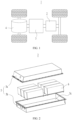
- FIG. 1 is a schematic structural diagram of a vehicle according to some embodiments of this application.
- the vehicle 1 is provided with a battery 2 inside, and the battery 2 may be disposed at the bottom or in the front or at the rear of the vehicle 1.
- the battery 2 may be configured to supply power to the vehicle 1.
- the battery 2 may be used as an operational power supply for the vehicle 1.
- the vehicle 1 may further include a controller 3 and a motor 4, and the controller 3 is configured to control the battery 2 to supply power to the motor 4, for example, to satisfy a working electricity need during start, navigation, and driving of the vehicle 1.
- the battery 2 can be used as not only the operational power supply for the vehicle 1 but also a driving power supply for the vehicle 1, replacing all or a part of the fossil fuel or the natural gas to provide driving power for the vehicle 1.
- FIG. 2 is a schematic exploded view of a battery according to some embodiments of this application.
- the battery 2 includes a box 5 and a battery cell (not shown), and the battery cell is accommodated in the box 5.
- the box 5 is configured to accommodate the battery cell, and the box 5 may have various structures.
- the box 5 may include a first box portion 5a and a second box portion 5b.
- the first box portion 5a and the second box portion 5b fit together to jointly define an accommodating space 5c for accommodating the battery cell.
- the second box portion 5b may be a hollow structure with an opening formed at an end, the first box portion 5a is a plate-shaped structure, and the first box portion 5a covers the opening side of the second box portion 5b so as to form the box 5 having the accommodating space 5c; and the first box portion 5a and the second box portion 5b may alternatively both be a hollow structure with an opening formed on a side, and the opening side of the first box portion 5a is engaged with the opening side of the second box portion 5b so as to form the box 5 having the accommodating space 5c.
- the first box portion 5a and the second box portion 5b may be in various shapes, such as cylinder and cuboid.
- a sealing member such as sealing gum and sealing ring may also be disposed between the first box portion 5a and the second box portion 5b.
- the first box portion 5a fits on a top of the second box portion 5b
- the first box portion 5a may also be referred to as an upper cover
- the second box portion 5b may also be referred to as a lower box.
- the multiple battery cells may be connected in series, parallel, or series-parallel, where being connected in series-parallel means a combination of series and parallel connections of the multiple battery cells.
- the multiple battery cells may be directly connected in series, parallel, or series-parallel, and then an entirety of the multiple battery cells is accommodated in the box 5; or certainly, the battery may be formed by multiple battery cells being connected in series, parallel, or series-parallel first to form a battery module 6 and then multiple battery modules 6 being connected in series, parallel, or series-parallel to form an entirety, which is accommodated in the box 5.
- FIG. 3 is a schematic exploded view of a battery module shown in FIG. 2 .
- FIG. 3 there are multiple battery cells 7, and the multiple battery cells 7 are connected in series, parallel, or series-parallel to form a battery module 6. Multiple battery modules 6 are then connected in series, parallel, or series-parallel to form an entirety which is accommodated in the box.
- the multiple battery cells 7 in the battery module 6 may be electrically connected via a busbar, so that the multiple battery cells 7 in the battery module 6 are connected in series, parallel, or series-parallel.
- FIG. 4 is a schematic structural diagram of a battery cell according to some embodiments of this application
- FIG. 5 is a schematic exploded view of a battery cell shown in FIG. 4 , where an adapter member is not bent
- FIG. 6 is a schematic cross-sectional view of the battery cell shown in FIG. 4
- FIG. 7 is a schematic enlarged view of the battery cell at circle A in FIG. 6
- FIG. 8 is a schematic structural diagram of an adapter member of a battery cell according to some embodiments of this application.
- the battery cell 7 of the embodiments of this application includes an electrode assembly 10, a housing 20, an electrode lead-out member 30, an adapter member 40, and a light absorbing layer 50.
- the housing 20 is provided with an accommodating cavity.
- the electrode lead-out member 30 is disposed at the housing 20.
- the electrode assembly 10 is accommodated in the accommodating cavity, where the electrode assembly 10 includes a main body portion 11 and a tab 12 led out of the main body portion 11.
- the adapter member 40 is configured to connect the tab 12 and the electrode lead-out member 30.
- the light absorbing layer 50 is applied to a welding position of the adapter member 40.
- the electrode assembly 10 is a component in which an electrochemical reaction takes place in the battery cell 7.
- the electrode assembly 10 may be a wound structure formed by a positive electrode plate, a separator, and a negative electrode plate through winding.
- the electrode assembly 10 may alternatively be a laminated structure formed by a positive electrode plate, a separator, and a negative electrode plate through lamination.
- the main body portion 11 may include a portion of the positive electrode plate coated with an active substance layer, a portion of the negative electrode plate coated with an active substance layer, and the separator. Active substances in the active substance layers are used for electrochemical reactions with the electrolyte and the like to produce charging and discharging processes.
- the tab 12 protrudes from the main body portion 11.
- the separator is configured to separate the positive electrode plate and the negative electrode plate, and the size of the separator is larger than the size of the positive electrode plate or the negative electrode plate, that is, the tab 12 protrudes from the separator.
- the positive electrode tab and negative electrode tab can be led out from the same end of the main body portion 11, or from opposite ends of the main body portion 11 respectively.
- the electrode lead-out member 30 may be part of the housing 20, or an independent component mounted on the housing 20.
- the light absorbing layer 50 is applied to the surface of the adapter member 40. In this case, the light absorbing layer 50 is in a complete state.
- one side of the adapter member 40 back away from the light absorbing layer 50 is enabled to abut against the to-be-welded component.
- the light absorbing layer 50 is disposed on the side of the adapter member 40 back away from the to-be-welded component.
- part of the light absorbing layer 50 on the surface of the adapter member 40 does not melt. Therefore, after the welding is completed, still part of the light absorbing layer 50 is retained on the surface of the adapter member 40.
- the adapter member 40 is welded to the tab 12 to form the welded portion 60, and the adapter member 40 is connected to the electrode lead-out member 30 through adhesion, riveting, clamping, or other non-welding methods.
- the adapter member 40 is welded to the electrode lead-out member 30 to form the welded portion 60, and the adapter member 40 is connected to the tab 12 through adhesion, riveting, clamping, or other non-welding methods.
- the welded portion 60 includes a first welded portion and a second welded portion, the adapter member 40 is welded to the tab 12 to form the first welded portion, and the adapter member 40 is welded to the electrode lead-out member 30 to form the second welded portion.
- the melted part of the light absorbing layer 50, the melted part of the adapter member 40, and the melted part of the to-be-welded component fuse together, solidifying to form the welded portion 60.
- part of the light absorbing layer 50 on the surface of the adapter member 40 does not melt, or even into the welded portion 60. Therefore, after the welding is completed, still part of the light absorbing layer 50 is retained on the surface of the adapter member 40, and this part of the light absorbing layer 50 may be disposed around the welded portion 60. For example, the retained light absorbing layer 50 is connected to the welded portion 60.
- the part of the light absorbing layer 50 retained around the welded portion 60 can reduce the risk of laser irradiation in the region of the adapter member 40 uncoated with the light absorbing layer 50 during the welding process, thereby reducing energy waste.
- the light absorbing layer 50 can further absorb scattered laser, reduce laser reflection, and fully absorb heat, thereby reducing the welding power.
- the shell 21 may be a structure with an opening at one side, and the end cover 22 is designed to cover the opening of the shell 21.
- the shell 21 may be a structure with openings at two sides, and the end cover 22 is provided in two, where the two end covers 22 cover the two openings of the shell 21 respectively.
- the end cover 22 can serve as the electrode lead-out member 30.
- the electrode lead-out member 30 may be an independent component mounted on the end cover 22.
- the electrode lead-out member 30 can also be called an electrode terminal.
- the main body portion 11 includes a separator configured to separate a positive electrode plate and a negative electrode plate, and a distance D between a region of the end face 121 used for welding to the adapter member 40 and the separator is 0.2 mm-3 mm.
- the size of the tab 12 protruding from the main body portion 11 is small, thereby reducing the space occupied by the tab 12 and increasing the energy density of the battery cell 7.
- This application reduces heat generated during the welding process with the arrangement of the light absorbing layer 50, ensuring that the main body portion 11 (especially the separator of the main body portion 11) is not easily burned even if the size of the tab 12 protruding from the main body portion 11 is small.
- the distance D between the region of the end face 121 used for welding to the adapter member 40 and the separator is 0.2 mm-1 mm. In this embodiment of this application, the size of the tab 12 protruding from the main body portion 11 can be further reduced.
- the tab 12 and the end face 121 of the adapter member 40 are formed through flattening.
- the flattened end face 121 can better fit with the adapter member 40, thereby enhancing the connection strength between the tab 12 and the adapter member 40.
- the protrusion 412 is configured to abut against and be welded to a to-be-welded component, to form the welded portion 60.
- the light absorbing layer 50 can be entirely applied to the bottom surface of the first recess 413 or only partially applied.
- the light absorbing layer 50 may further be applied to other regions of the adapter member 40.
- the first recess 413 can position the light absorbing layer 50, facilitating the application of the light absorbing layer 50.
- the protrusion 412 protrudes at a position corresponding to the first recess 413, which ensures both the depth of the first recess 413 and the strength of the welded portion 60.
- the adapter member 40 further includes a base 411, the base 411 has a first surface 411a and a second surface 411b opposite each other, the protrusion 412 protrudes from the first surface 411a, and the first recess 413 is recessed relative to the second surface 411b.
- the first surface 411a faces the to-be-welded component, while the second surface 411b is back away from the to-be-welded component.
- the light absorbing layer 50 may further be applied to the second surface 411b.
- the protrusion 412 is used for welding with the tab 12 to form the welded portion 60.
- the protrusion 412 can be embedded into the tab 12 to ensure tight contact between the protrusion 412 and the tab 12, reducing the risk of false welding and increasing the strength of the welded portion 60.
- the base 411 is plate-shaped.
- multiple protrusions 412 are provided and spaced apart.
- the adapter member 40 includes a first connecting portion 41, which includes a base 411 and a protrusion 412.
- the adapter member 40 further includes a second connecting portion 42 and a third connecting portion 43.
- the second connecting portion 42 extends from one end of the base 411 and bends to the side of the base 411 back away from the tab 12.
- the third connecting portion 43 extends from the end of the second connecting portion 42 away from the base 411 and bends to the side of the second connecting portion 42 back away from the first connecting portion 41.
- the third connecting portion 43 is configured to connect the electrode lead-out member 30.
- FIG. 8 shows the state of the adapter member 40 before bending.
- At least part of the third connecting portion 43 is clamped between the end cover 22 and the electrode lead-out member 30 to achieve the connection between the third connecting portion 43 and the electrode lead-out member 30.
- FIG. 9 is a schematic diagram of an assembly process of a battery cell according to some embodiments of this application.
- At least part of the light absorbing layer 50 is arranged around the welded portion 60.
- This embodiment can reduce the risk of laser irradiation due to an error in the region of the adapter member 40 uncoated with the light absorbing layer 50, and improve the energy utilization rate.
- the annular light absorbing layer 50 can further absorb scattered laser, reduce laser reflection, and fully absorb heat, thereby reducing the welding power.
- the light absorbing layer 50 and the welded portion 60 are different in color.
- the adapter member 40 can be positioned with the welded portion 60 as a reference.
- This embodiment causes a color difference between the light absorbing layer 50 and the welded portion 60, making it easier for an external detection device to detect a location of the welded portion 60. This helps to position the adapter member 40 and improve the assembly efficiency of the battery cell 7.
- the light absorbing layer 50 is black.
- the black light absorbing layer 50 has better light absorbing property, and can reduce reflection, increase the energy absorption rate, lower the welding power, and reduce the possibility of other components of the battery cell 7 being burned, thus improving the safety of the battery cell 7.
- the light absorbing layer 50 includes a chromium-containing material.
- the chromium-containing material has good light-absorbing property.
- the light absorbing layer 50 may include copper-chromium black.
- the light absorbing layer 50 also includes aluminium oxide doped into the copper-chromium black.
- the light absorbing layer 50 may include a black cobalt-containing ceramic pigment.
- an amount of chromium contained in the welded portion 60 is greater than an amount of chromium contained in an unwelded portion of the adapter member 40.
- the unwelded portion of the adapter member 40 refers to part of the adapter member 40 that is not welded to the to-be-welded component.
- part of the chromium-containing metal melts into the welded portion 60 during the welding process.
- These chromium-containing metals are conductive, ensuring the current-carrying capacity of the welded portion 60 even if the chromium-containing metal melts into the welded portion 60.
- the thickness of the light absorbing layer 50 is 0.1 ⁇ m-50 ⁇ m.
- the thickness of the light absorbing layer 50 is 0.1 ⁇ m, 0.2 ⁇ m, 0.5 ⁇ m, 0.6 ⁇ m, 1 ⁇ m, 2 ⁇ m, 5 ⁇ m, 10 ⁇ m, 15 ⁇ m, 20 ⁇ m, 25 ⁇ m, 35 ⁇ m, or 50 ⁇ m.
- the thickness of the light absorbing layer 50 is 0.8 ⁇ m-25 ⁇ m.
- surface roughness of part of the adapter member 40 coated with the light absorbing layer 50 is greater than surface roughness of part of the adapter member 40 uncoated with the light absorbing layer 50.
- the region of the adapter member 40 that needs to be coated with the light absorbing layer 50 may be sandblasted to improve the local surface roughness of the adapter member 40.
- FIG. 10 is a schematic structural diagram of an adapter member of a battery cell according to some other embodiments of this application.
- the light absorbing layer 50 is applied to the bottom surface of the first recess 413 and the second surface 411b.
- a coating device can apply it directly to the entire first connecting portion 41 without positioning the first recess 413, thereby improving the coating efficiency.
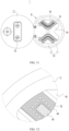
- FIG. 11 is a schematic diagram of an assembly process of a battery cell according to some other embodiments of this application;
- FIG. 12 is a schematic enlarged view of the battery cell at circle B in FIG. 11 ;
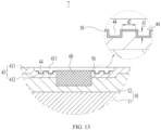
- FIG. 13 is a locally schematic cross-sectional view of the battery cell shown in FIG. 11 .
- a surface of the adapter member 40 coated with the light absorbing layer 50 is provided with multiple second recesses 44, and the multiple second recesses 44 are arranged on an outer side of the welded portion 60.
- the adapter member 40 is provided with the multiple second recesses 44, resulting in an uneven surface of the adapter member 40, thus further reducing reflection, increasing the energy absorption rate of the adapter member 40, and lowering the welding power, reducing the possibility of other components of the battery cell 7 being burned, so as to improve the safety of the battery cell 7.
- the second recess 44 may be cylindrical, prismatic, hemispherical, conical, or of other shapes.
- the region of the adapter member 40 provided with the second recess 44 is used for welding to the to-be-welded component. After welding is completed, part of the second recess 44 disappears.
- the light absorbing layer 50 surrounds an outer side of each of the second recesses 44.
- the concave surface of the second recess 44 can reduce the high reflection frequency, and the light absorbing layer 50 surrounding the outer side of the second recess 44 can absorb light.
- the combination of the two can better reduce reflection, improve the energy absorption rate, and reduce the welding power.
- the light absorbing layer 50 covers a bottom surface of the second recess 44.
- the area of the light absorbing layer 50 and the energy absorption rate can be increased, and the coating process of the light absorbing layer 50 can be also simplified.
- a thickness of the light absorbing layer 50 is less than a depth of the second recess 44.
- This embodiment can avoid the second recess 44 being filled up by the light absorbing layer 50, thereby retaining the concave structure on the adapter member 40, reducing the high reflection frequency, increasing the energy absorption rate, and reducing the welding power.
- the depth d1 of the second recess 44 is 0.01 mm-0.5 mm.
- the bottom surface of the second recess 44 may be planar or curved.
- the bottom surface of the second recess 44 may be an arc surface.
- the depth d1 of the second recess 44 is the maximum dimension of the second recess 44 in the thickness direction of the adapter member 40. In other words, the depth d1 of the second recess 44 is the maximum spacing thereof between the opening of the second recess 44 and the bottom surface of the second recess 44 in the thickness direction of the adapter member 40.
- This embodiment limits the depth d1 of the second recess 44 to 0.01 mm-0.5 mm, on the premise of ensuring the strength of the welded portion 60, reducing the high reflection frequency, increasing the energy absorption rate, and reducing the welding power.
- the depth d1 of the second recess 44 is 0.01mm, 0.05mm, 0.1mm, 0.2mm, 0.3mm, or 0.5mm. In some embodiments, the depth d1 of the second recess 44 is 0.05 mm-0.3 mm.
- the area of the second recess 44 is 0.04 mm 2 -200 mm 2 .
- the area of the second recess 44 may be the area of the opening of the second recess 44.
- the second recess 44 is formed on the bottom surface of the first recess 413.
- the opening of the second recess 44 may be the opening of the second recess 44 formed on the bottom surface of the first recess.
- This embodiment limits the area of the second recess 44 to 0.04 mm 2 -200 mm 2 , to balance a process requirement and the effect of reducing the high reflection frequency of the second recess 44.
- the area of the second recess 44 is 0.04 mm 2 , 0.25 mm 2 , 1 mm 2 , 5 mm 2 , 10 mm 2 , 50 mm 2 , 100 mm 2 , or 200 mm 2 .
- the area of the second recess 44 is 0.25 mm 2 -100 mm 2 .
- the spacing d2 between adjacent second recesses 44 is 0.1 mm-5 mm.
- the spacing d2 between adjacent second recesses 44 refers to the minimum spacing between the side surfaces of the adjacent second recesses 44.
- This embodiment limits the spacing d2 between adjacent second recesses 44 to 0.1 mm-5 mm, to balance a process requirement and the effect of reducing the high reflection frequency of the second recess 44.
- the spacing d2 between adjacent second recesses 44 is 0.1 mm, 0.2 mm, 0.5 mm, 1 mm, 2 mm, 3 mm, 4 mm, or 5 mm.
- the second recess 44 may be made by embossing.
- the region of the adapter member 40 used for providing the second recess 44 has been sandblasted.
- FIG. 14 is a schematic exploded view of a battery cell according to still some other embodiments of this application;
- FIG. 15 is a schematic cross-sectional view of the battery cell shown in FIG. 14 ;
- FIG. 16 is a schematic enlarged view of the battery cell at circle C in FIG. 15 .
- the housing 20 is rectangular.
- the adapter member 40 is welded to the electrode lead-out member 30 to form the welded portion 60.
- the adapter member 40 includes a base 411 and a protrusion 412.
- the base 411 has a first surface and a second surface opposite each other, the protrusion 412 protrudes from the first surface, and the welded portion 60 is formed on the protrusion 412.
- the first connecting portion 41 has a first recess 413 formed at a position corresponding to the protrusion 412, and the first recess 413 is recessed relative to the second surface.
- the light absorbing layer 50 is at least applied to a bottom surface of the first recess 413.
- the protrusion 412 is configured to abut against and be welded to the electrode lead-out member 30.
- this application further provides a battery including multiple battery cells according to any one of the foregoing embodiments.
- this application further provides an electric apparatus, including the battery cell of any one of the foregoing embodiments, where the battery cell is configured to provide electric energy.
- the battery cell 7 includes an electrode assembly 10, a housing 20, an electrode lead-out member 30, and an adapter member 40.
- the housing 20 is provided with an accommodating cavity.
- the electrode lead-out member 30 is disposed at the housing 20.
- the electrode assembly 10 is accommodated in the accommodating cavity, where the electrode assembly 10 includes a main body portion 11 and a tab 12 led out of the main body portion 11.
- the adapter member 40 is configured to connect the tab 12 and the electrode lead-out member 30.
- the surface of the adapter member 40 is coated with a light absorbing layer 50.
- the adapter member 40 is welded to the tab 12 to form the welded portion 60, and the light absorbing layer 50 surrounds the welded portion 60.
- the light absorbing layer 50 is black and includes a chromium-containing material.
- the adapter member 40 includes a first connecting portion 41, which includes a base 411 and a protrusion 412.
- the base 411 has a first surface 411a and a second surface 411b opposite each other.
- the protrusion 412 protrudes from the first surface 411a and is welded to the tab 12 to form the welded portion 60.
- the first connecting portion 41 is provided with a first recess 413 at a position corresponding to the protrusion 412, and the first recess 413 is recessed relative to the second surface 411b.
- the light absorbing layer 50 is applied to a bottom surface of the first recess 413.
Landscapes
- General Chemical & Material Sciences (AREA)
- Chemical & Material Sciences (AREA)
- Chemical Kinetics & Catalysis (AREA)
- Electrochemistry (AREA)
- Engineering & Computer Science (AREA)
- Optics & Photonics (AREA)
- Physics & Mathematics (AREA)
- Plasma & Fusion (AREA)
- Mechanical Engineering (AREA)
- Aviation & Aerospace Engineering (AREA)
- Manufacturing & Machinery (AREA)
- Connection Of Batteries Or Terminals (AREA)
- Gas Exhaust Devices For Batteries (AREA)
Applications Claiming Priority (2)
| Application Number | Priority Date | Filing Date | Title |
|---|---|---|---|
| PCT/CN2022/077890 WO2023159463A1 (zh) | 2022-02-25 | 2022-02-25 | 电池单体及其制造方法和制造系统、电池以及用电装置 |
| PCT/CN2022/120299 WO2023159928A1 (zh) | 2022-02-25 | 2022-09-21 | 电池单体、电池以及用电装置 |
Publications (2)
| Publication Number | Publication Date |
|---|---|
| EP4481911A1 true EP4481911A1 (de) | 2024-12-25 |
| EP4481911A4 EP4481911A4 (de) | 2025-09-17 |
Family
ID=87764239
Family Applications (1)
| Application Number | Title | Priority Date | Filing Date |
|---|---|---|---|
| EP22928194.4A Pending EP4481911A4 (de) | 2022-02-25 | 2022-09-21 | Batteriezelle, batterie und elektrische vorrichtung |
Country Status (4)
| Country | Link |
|---|---|
| US (1) | US20240413492A1 (de) |
| EP (1) | EP4481911A4 (de) |
| CN (2) | CN221805790U (de) |
| WO (2) | WO2023159463A1 (de) |
Families Citing this family (1)
| Publication number | Priority date | Publication date | Assignee | Title |
|---|---|---|---|---|
| CN121238099A (zh) * | 2024-06-28 | 2025-12-30 | 宁德时代新能源科技股份有限公司 | 电池、用电装置、储能装置及电池制造方法 |
Family Cites Families (11)
| Publication number | Priority date | Publication date | Assignee | Title |
|---|---|---|---|---|
| JPS62283554A (ja) * | 1986-06-02 | 1987-12-09 | Fuji Elelctrochem Co Ltd | リ−ド端子付き電池の製造方法 |
| JP2005288947A (ja) * | 2004-04-01 | 2005-10-20 | Seiko Precision Inc | 接合方法、接合部材及び部品 |
| KR101435596B1 (ko) * | 2011-03-14 | 2014-08-28 | 파나소닉 주식회사 | 레이저 접합 부품 및 그 제조 방법 |
| CN102560015B (zh) * | 2012-03-07 | 2013-10-09 | 中国船舶重工集团公司第十二研究所 | 一种采用激光淬火对模具型面进行处理的方法 |
| KR101726909B1 (ko) * | 2013-10-23 | 2017-04-13 | 삼성에스디아이 주식회사 | 광흡수 부재를 갖는 이차 전지 |
| CN105467499A (zh) * | 2016-01-15 | 2016-04-06 | 京东方科技集团股份有限公司 | 一种金属线栅偏振片及其制造方法、显示面板及显示装置 |
| CN209312882U (zh) * | 2018-12-07 | 2019-08-27 | 东莞塔菲尔新能源科技有限公司 | 一种动力电池转接片结构及动力电池 |
| CN209312876U (zh) * | 2018-12-07 | 2019-08-27 | 东莞塔菲尔新能源科技有限公司 | 一种动力电池转接片结构及动力电池 |
| CN209754274U (zh) * | 2019-01-11 | 2019-12-10 | 泰科电子(上海)有限公司 | 连接组件 |
| CN209880722U (zh) * | 2019-06-28 | 2019-12-31 | 宁德时代新能源科技股份有限公司 | 二次电池 |
| CN118738778A (zh) * | 2020-09-30 | 2024-10-01 | 宁德时代新能源科技股份有限公司 | 圆柱型电池单体、电池、用电装置、制造方法及制造系统 |
-
2022
- 2022-02-25 CN CN202290000466.XU patent/CN221805790U/zh active Active
- 2022-02-25 WO PCT/CN2022/077890 patent/WO2023159463A1/zh not_active Ceased
- 2022-09-21 WO PCT/CN2022/120299 patent/WO2023159928A1/zh not_active Ceased
- 2022-09-21 EP EP22928194.4A patent/EP4481911A4/de active Pending
- 2022-09-21 CN CN202290000468.9U patent/CN221805682U/zh active Active
-
2024
- 2024-08-23 US US18/813,076 patent/US20240413492A1/en active Pending
Also Published As
| Publication number | Publication date |
|---|---|
| CN221805682U (zh) | 2024-10-01 |
| WO2023159463A1 (zh) | 2023-08-31 |
| EP4481911A4 (de) | 2025-09-17 |
| US20240413492A1 (en) | 2024-12-12 |
| CN221805790U (zh) | 2024-10-01 |
| WO2023159928A1 (zh) | 2023-08-31 |
Similar Documents
| Publication | Publication Date | Title |
|---|---|---|
| EP4106088B1 (de) | Batteriezelle, batterie und elektrische vorrichtung | |
| EP4293769A1 (de) | Batteriezelle, batterie und elektrische vorrichtung | |
| EP4184669B1 (de) | Bodenzelle und herstellungsverfahren und herstellungssystem dafür, batterie und stromverbrauchende vorrichtung | |
| US20250105476A1 (en) | Adapting member, battery cell, battery, and electric apparatus | |
| JP7739414B2 (ja) | 電池セル、その製造方法及び製造システム、電池並びに電力消費装置 | |
| EP4181279A1 (de) | Batteriezelle, verfahren und system zur herstellung davon, batterie und elektrische vorrichtung | |
| US12463274B2 (en) | Battery cell, method and system for manufacturing same, battery, and electrical device | |
| EP4170781B1 (de) | Batteriezelle, verfahren und system zur herstellung einer batteriezelle, batterie und elektrische vorrichtung | |
| EP4517946A1 (de) | Batteriezelle, batterie und elektrische vorrichtung | |
| EP4439815A1 (de) | Batteriezelle, batterie und elektrische vorrichtung | |
| EP4401223A1 (de) | Druckentlastungsvorrichtung, gehäuse, batteriezelle, batterie und elektrische vorrichtung | |
| US20240097287A1 (en) | Battery cell, method and system for manufacture same, battery, and power consuming device | |
| EP4691682A1 (de) | Strukturelement und herstellungsverfahren dafür, batteriezelle, batterie und elektrische vorrichtung | |
| US20250087854A1 (en) | Battery cell, battery, and electric apparatus | |
| EP4102607B1 (de) | Elektrodenanordnung, batteriezelle, batterie sowie verfahren zur herstellung dieser elektrodenanordnung | |
| US20240162579A1 (en) | Battery cell, method and system for manufacturing battery cell, battery and electrical apparatus | |
| US20240413492A1 (en) | Battery cell, battery, and electric apparatus | |
| EP4293811A1 (de) | Laschenschweissstruktur, batteriezelle und elektrische vorrichtung | |
| EP4391183A1 (de) | Endkappe, batteriezelle, batterie und elektrische vorrichtung | |
| US12614822B2 (en) | Battery cell, method and system for manufacturing same, battery, and electrical device | |
| US12476333B2 (en) | Battery cell having conductive piece close to welding region | |
| EP4510348A1 (de) | Batteriezelle, batterie und elektrische vorrichtung | |
| EP4432447A1 (de) | Elektrodenanordnung, batteriezelle, batterie und elektrische vorrichtung | |
| EP4521530A1 (de) | Batteriezelle, batterie und elektrische vorrichtung | |
| EP4354638A1 (de) | Batteriezelle und herstellungsverfahren und vorrichtung dafür, batterie und elektrische vorrichtung |
Legal Events
| Date | Code | Title | Description |
|---|---|---|---|
| STAA | Information on the status of an ep patent application or granted ep patent |
Free format text: STATUS: THE INTERNATIONAL PUBLICATION HAS BEEN MADE |
|
| PUAI | Public reference made under article 153(3) epc to a published international application that has entered the european phase |
Free format text: ORIGINAL CODE: 0009012 |
|
| STAA | Information on the status of an ep patent application or granted ep patent |
Free format text: STATUS: REQUEST FOR EXAMINATION WAS MADE |
|
| 17P | Request for examination filed |
Effective date: 20240920 |
|
| AK | Designated contracting states |
Kind code of ref document: A1 Designated state(s): AL AT BE BG CH CY CZ DE DK EE ES FI FR GB GR HR HU IE IS IT LI LT LU LV MC MK MT NL NO PL PT RO RS SE SI SK SM TR |
|
| DAV | Request for validation of the european patent (deleted) | ||
| DAX | Request for extension of the european patent (deleted) | ||
| A4 | Supplementary search report drawn up and despatched |
Effective date: 20250820 |
|
| RIC1 | Information provided on ipc code assigned before grant |
Ipc: H01M 50/172 20210101AFI20250813BHEP Ipc: H01M 10/052 20100101ALI20250813BHEP Ipc: H01M 50/531 20210101ALI20250813BHEP Ipc: B23K 26/21 20140101ALI20250813BHEP Ipc: H01M 50/528 20210101ALI20250813BHEP Ipc: H01M 50/536 20210101ALI20250813BHEP Ipc: H01M 50/566 20210101ALI20250813BHEP Ipc: B23K 26/18 20060101ALI20250813BHEP |