EP4481996A1 - Dispositif de serrage pour stator - Google Patents
Dispositif de serrage pour stator Download PDFInfo
- Publication number
- EP4481996A1 EP4481996A1 EP23181178.7A EP23181178A EP4481996A1 EP 4481996 A1 EP4481996 A1 EP 4481996A1 EP 23181178 A EP23181178 A EP 23181178A EP 4481996 A1 EP4481996 A1 EP 4481996A1
- Authority
- EP
- European Patent Office
- Prior art keywords
- leg
- clamping device
- stator
- state
- electric motor
- Prior art date
- Legal status (The legal status is an assumption and is not a legal conclusion. Google has not performed a legal analysis and makes no representation as to the accuracy of the status listed.)
- Withdrawn
Links
Images



Classifications
-
- H—ELECTRICITY
- H02—GENERATION; CONVERSION OR DISTRIBUTION OF ELECTRIC POWER
- H02K—DYNAMO-ELECTRIC MACHINES
- H02K3/00—Details of windings
- H02K3/46—Fastening of windings on the stator or rotor structure
- H02K3/52—Fastening salient pole windings or connections thereto
- H02K3/521—Fastening salient pole windings or connections thereto applicable to stators only
- H02K3/522—Fastening salient pole windings or connections thereto applicable to stators only for generally annular cores with salient poles
-
- H—ELECTRICITY
- H02—GENERATION; CONVERSION OR DISTRIBUTION OF ELECTRIC POWER
- H02K—DYNAMO-ELECTRIC MACHINES
- H02K7/00—Arrangements for handling mechanical energy structurally associated with dynamo-electric machines, e.g. structural association with mechanical driving motors or auxiliary dynamo-electric machines
- H02K7/14—Structural association with mechanical loads, e.g. with hand-held machine tools or fans
- H02K7/145—Hand-held machine tool
-
- H—ELECTRICITY
- H02—GENERATION; CONVERSION OR DISTRIBUTION OF ELECTRIC POWER
- H02K—DYNAMO-ELECTRIC MACHINES
- H02K2203/00—Specific aspects not provided for in the other groups of this subclass relating to the windings
- H02K2203/09—Machines characterised by wiring elements other than wires, e.g. bus rings, for connecting the winding terminations
Definitions
- the present invention relates to a clamping device for a stator of an electric motor, in particular as a drive for a machine tool.
- the present invention relates to a stator for an electric motor with at least one clamping device.
- the present invention relates to a machine tool with a stator for an electric motor.
- Electric motors are known from the prior art which include, among other things, a stator and a rotor which can rotate relative to the stator.
- a stator For the electric motor to function and in particular for the optional generation of a magnetic field, it is necessary for the stator to have a large number of coil windings around the respective pole teeth or stator teeth.
- a winding wire is wound in several layers around the pole tooth or stator tooth.
- the pole tooth or stator tooth serves as a carrier for the coil winding.
- the respective free ends of a winding wire are contacted or energized at the so-called distribution strip.
- Clamps or clamping devices are used to hold the free ends of the winding wire and supply them with electrical energy.
- the object is achieved in particular by a clamping device for a stator of an electric motor, in particular as a drive for a machine tool.
- a carrier element is provided with a connection element and at least a first and a second claw element for each receiving a winding wire.
- each claw element may contain an elastically deformable leg which can be set to a first or second state, wherein in the first state the leg is undeformed and in the second state the leg is deformed such that at least one winding wire is received and held. This makes it possible to releasably connect a winding wire to a claw element in a simple manner.
- the carrier element prefferably has more than one connection element and/or more than two claw elements for each of which can accommodate a winding wire.
- the leg may have a length such that, in a second state of the leg, at least one first and second winding wire with a cross-sectional area of between 1.5 and 2 mm 2 , and in particular 1.8 mm 2 , can be accommodated. This makes it possible to transmit a particularly high current intensity.
- a first section at a first end of the leg lies essentially parallel to a second section at a second end of the leg and a receiving space for a winding wire is created between the first and second ends of the leg.
- the clamping device may consist at least partially of a low-alloyed copper alloy with a relatively low tin content and a relatively high electrical conductivity, in particular of CuSn0.15.
- a stator for an electric motor with at least one clamping device containing a carrier element with a connection element and at least a first and second claw element.
- a machine tool with a stator for an electric motor comprising at least one clamping device with a carrier element with a connection element and at least one first and second claw element.
- Figure 1 shows a machine tool 1 according to an exemplary embodiment.
- the machine tool 1 is designed in the form of a battery-operated drill.
- the machine tool can also be designed in the form of a saw, a grinder, a hammer drill or the like.
- the machine tool 1 designed as a drilling machine essentially contains a housing 2, a handle 3, a tool holder 4 and a power supply 5.
- the housing 2 has a front end 2a, a rear end 2b, an upper end 2c and a lower end 2d.
- the tool holder 4 is positioned at the front end 2a of the housing 2.
- the tool holder 4 serves to pick up and hold a tool 6.
- the tool 6 is designed in the form of a drill.
- a first end 3a of the handle 3 is positioned at the lower end 2d of the housing 2.
- a battery interface 7 is provided at the second end 3b of the handle 3.
- the handle 3 has an activation switch 8 with which the machine tool 1 can be set to an activation state or a deactivation state.
- the energy supply 5 can be releasably attached to the battery interface 7.
- the energy supply 5 is designed in the form of a battery.
- the energy supply 5 serves to supply the machine tool with electrical energy.
- the energy supply 5 can also be designed as a power cable for connecting the machine tool 1 to a mains power source (socket).
- the energy supply 5 designed as a power cable is not shown in the figures.
- a drive 9, a transmission device 10, a drive shaft 11 and a control device 12 are positioned inside the housing 2.
- the drive 9, the gear device 10, the drive shaft 11 and the tool holder 4 are arranged in relation to one another inside the housing 2 in such a way that a torque generated in the drive 9 can be transmitted to the gear device 10, the drive shaft 11 and finally to the tool holder 4 or to the tool 6.
- the control device 12 is connected to the activation switch 8, the battery interface 7 and the drive 9 by means of corresponding lines 13.
- the energy supply 5 designed as a rechargeable battery can be releasably connected to the machine tool 1 in order to supply the machine tool 1 with electrical energy.
- the rechargeable battery 5 essentially contains a battery housing 40, a number of energy storage cells 13, a battery interface 14 and a control device 15.
- the energy storage cells 13 can also be referred to as battery cells and are arranged inside the battery housing 40.
- the battery housing 40 essentially contains a cover element 40a, four side walls 40b and a base element 40c.
- the battery interface 14 is arranged on the outside of the cover element 40a and serves for the electrical or electronic as well as mechanical connection of the battery 5 to the machine tool 1 or a charging device.
- the charging device is used to charge the accumulator 5 with electrical energy.
- the charging device is not shown in the figures.
- the battery interface 14 has a positive contact, a negative contact and a communication contact.
- the positive and negative contacts are used to create an electrical circuit when the battery 5 is connected to a machine tool 1 or a charging device.
- the communication contact is used to send and receive data and information in the form of electrical signals.
- the accumulator 5 can also contain radio communication (e.g. Bluetooth) or wireless communication.
- radio communication e.g. Bluetooth
- wireless communication e.g.
- the energy storage cells 13 are used to absorb, store and release electrical energy.
- the energy storage cells 13 are cylindrical in shape and are designed based on lithium-ion technology.
- Each energy storage cell 13 contains a contact device at one end which is used to transmit electrical energy.
- the individual contact devices are connected to the control device 15 of the accumulator 5 via corresponding lines.
- the energy storage cells 13 may also be based on another suitable technology.
- the cylindrical shape of the energy storage cells 13 is also optional, so that any other suitable shape or geometry can be selected.
- the energy storage cells 13 it is also possible for the energy storage cells 13 to be designed as pouch cells.
- the accumulator 5 may contain both cylindrical energy storage cells 13 and pouch cells. In particular, it is possible for the accumulator 5 to contain only a single cylindrical energy storage cell 13 and a single pouch cell.
- the control device 15 regulates and controls various functions of the accumulator 5.
- the functions include, among others, the control of the absorption and release of electrical energy into and from the energy storage cells 13.
- the control device 15 is used to control the amount of electrical energy that is to be absorbed or released by the energy storage cells 13.
- the drive 9 is designed in the form of a brushless electric motor and essentially contains a stator 16 and a rotor 17, cf. Figure 2 .
- the rotor 17 is positioned inside the stator 16 and is also designed to be rotatable relative to the stator 16.
- Figure 3 shows an upper end 16a of the stator 16 according to an exemplary embodiment.
- a lower end 16b of the stator 16 is arranged opposite the upper end 16a.
- the stator 16 shown as an example in the figures contains a laminated core 18, a winding support 27, six coils 26 each with a first and second winding wire 21, 22, a collecting unit 23 and six clamping devices 24.
- the coil 26 is also referred to as a winding coil.
- the electric motor 9 shown in the figures is designed as a synchronous three-phase motor, wherein the winding wires 21, 22 (also referred to as power wires) realize the U-phase, V-phase and W-phase.
- the sheet package 18 essentially consists of a number of profile sheets stacked on top of each other.
- Six pole teeth 25 extend to the center of the laminated core 18, only indicated.
- a first and a second winding wire 21, 22 are wound around each individual pole tooth 25 to form a coil 26.
- a winding support 27 is arranged at the respective ends 16a, 16b of the stator 16 to support or hold the coil 26 wound from the winding wires 21, 22.
- the upper end 16a of the stator 16 is shown with a winding support 27.
- the coils 26 or the first and second winding wires 21, 22 are covered with a plastic 28 which serves to insulate the coil 26.
- a free end 21a, 22a of the first and second winding wires 21, 22 protrudes from the upper end 26a of each coil 26 from the insulating plastic 28.
- the free ends 21a, 22a of the first and second winding wires 21, 22 thus extend in the direction N.
- the collecting unit 23 is arranged in the direction N above the winding support 27 and serves essentially to hold or position the six clamping devices 24.
- the clamping devices 24 in turn serve to receive and hold the free ends 21a, 22a of the first and second winding wires 21, 22.
- the clamping devices 24 serve as a connection for the power supply or the supply of electrical energy to the winding wires 21, 22 for generating the U-phase, V-phase and W-phase during operation of the drive 9 designed as an electric motor.
- each clamping device 24 contains a carrier element 29 with a connection element 30 and a first and second claw element 31, 32.
- the carrier element 29 is essentially designed as an elongated base plate.
- the carrier element 29 designed as an elongated base plate has a first end 29a and a second end 29b as well as an upper edge 29c and a lower edge 29d.
- the connection element 30 is positioned at the first end 29a of the carrier element 29.
- the connection element 30 serves as a connection point for a line for the power supply.
- the first claw element 31 is positioned at the lower edge 29d and at the second end 29b of the support element 29.
- the second claw element 32 is positioned near the second end 29b of the support element 29.
- Each claw element 31, 32 includes an elastically deformable leg 33 which is adjustable to a first or second state.
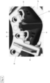
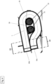
- the leg 33 In the first state, the leg 33 is undeformed or opened, cf. Figure 5 . In the second state, the leg 33 is deformed so that the first and second winding wire 21, 22 can be received and held, cf. Figure 3 and 4 .
- a leg 33 of a claw element 31, 32 is shown in a second state or in a deformed position, so that the first and second winding wires 21, 22 are held by the leg 33 of the claw element 31, 32.
- the leg 33 has in particular a length L, so that in the second state, ie deformed state of the leg 33, the first and second winding wire 21, 22 with a cross-sectional area between 1.5 to 2 mm 2 , and in particular 1.8 mm 2 , can be accommodated.
- a first (free) portion 34 of the first end 33a of the leg 33 is in the Essentially parallel to a second section 35 at a second end 33b of the leg 33. This creates a receiving space 36 for the first and second winding wires 21, 22 between the first end 33a and the second end 33b of the leg 33.
- the clamping device 24 consists at least partially of a low-alloy copper alloy with a relatively low tin content and a relatively high electrical conductivity, in particular of CuSn0.15.
Landscapes
- Engineering & Computer Science (AREA)
- Power Engineering (AREA)
- Windings For Motors And Generators (AREA)
- Insulation, Fastening Of Motor, Generator Windings (AREA)
Priority Applications (2)
| Application Number | Priority Date | Filing Date | Title |
|---|---|---|---|
| EP23181178.7A EP4481996A1 (fr) | 2023-06-23 | 2023-06-23 | Dispositif de serrage pour stator |
| PCT/EP2024/065571 WO2024260737A1 (fr) | 2023-06-23 | 2024-06-06 | Dispositif de serrage pour un stator |
Applications Claiming Priority (1)
| Application Number | Priority Date | Filing Date | Title |
|---|---|---|---|
| EP23181178.7A EP4481996A1 (fr) | 2023-06-23 | 2023-06-23 | Dispositif de serrage pour stator |
Publications (1)
| Publication Number | Publication Date |
|---|---|
| EP4481996A1 true EP4481996A1 (fr) | 2024-12-25 |
Family
ID=87047833
Family Applications (1)
| Application Number | Title | Priority Date | Filing Date |
|---|---|---|---|
| EP23181178.7A Withdrawn EP4481996A1 (fr) | 2023-06-23 | 2023-06-23 | Dispositif de serrage pour stator |
Country Status (2)
| Country | Link |
|---|---|
| EP (1) | EP4481996A1 (fr) |
| WO (1) | WO2024260737A1 (fr) |
Citations (2)
| Publication number | Priority date | Publication date | Assignee | Title |
|---|---|---|---|---|
| DE102010025261A1 (de) * | 2010-06-23 | 2011-12-29 | C. & E. Fein Gmbh | Elektromotor |
| DE102013105571A1 (de) * | 2013-05-29 | 2014-12-04 | Ebm-Papst St. Georgen Gmbh & Co. Kg | Kontaktelement zur Kontaktierung mindestens eines Wicklungsdrahts |
-
2023
- 2023-06-23 EP EP23181178.7A patent/EP4481996A1/fr not_active Withdrawn
-
2024
- 2024-06-06 WO PCT/EP2024/065571 patent/WO2024260737A1/fr not_active Ceased
Patent Citations (2)
| Publication number | Priority date | Publication date | Assignee | Title |
|---|---|---|---|---|
| DE102010025261A1 (de) * | 2010-06-23 | 2011-12-29 | C. & E. Fein Gmbh | Elektromotor |
| DE102013105571A1 (de) * | 2013-05-29 | 2014-12-04 | Ebm-Papst St. Georgen Gmbh & Co. Kg | Kontaktelement zur Kontaktierung mindestens eines Wicklungsdrahts |
Also Published As
| Publication number | Publication date |
|---|---|
| WO2024260737A1 (fr) | 2024-12-26 |
Similar Documents
| Publication | Publication Date | Title |
|---|---|---|
| DE102012100668A1 (de) | Elektromotor | |
| DE112015001742B4 (de) | Elektrisches Kraftwerkzeug | |
| DE112017000288B4 (de) | Stator für elektrische Rotationsmaschine und elektrische Rotationsmaschine, die ihn verwendet | |
| EP3918695B1 (fr) | Entraînement électrique et procédé servant à faire fonctionner l'entraînement électrique | |
| DE102008054520A1 (de) | Stator in einem Elektromotor | |
| DE102010002154A1 (de) | Ladesystem zum Laden eines Energiespeichers in einem Fahrzeug und Verfahren zur Vorbereitung eines Ladebetriebs eines Energiespeichers in einem Fahrzeug | |
| DE112021007306T5 (de) | Rotor für rotierende elektrische maschine und rotierende elektrische maschine | |
| EP4481996A1 (fr) | Dispositif de serrage pour stator | |
| EP3471235A2 (fr) | Dispositif de fourniture d'énergie destiné à fournir de l'énergie électrique à un véhicule automobile ainsi que procédé de fonctionnement d'un dispositif de fourniture d'énergie | |
| EP0664599B1 (fr) | Moteur à commutateur | |
| WO2022268513A1 (fr) | Machine-outil et son procédé de fonctionnement | |
| DE19945994A1 (de) | Energieversorgung eines elektrischen Handgeräts | |
| EP4597801A1 (fr) | Stator multi-jonctions | |
| EP2603966A1 (fr) | Porte-pièce pour un bloc statorique | |
| EP4651342A1 (fr) | Segments magnétiques pour un rotor | |
| EP4614767A1 (fr) | Rotor à aimants amovibles | |
| EP4550627A1 (fr) | Segments magnétiques pour un rotor | |
| EP4503403A1 (fr) | Résistance intégrée dans un dissipateur de chaleur électronique | |
| WO2025026757A1 (fr) | Résistance de freinage de moteur intégrée | |
| DE202010009961U1 (de) | Elektromotor | |
| EP4503402A1 (fr) | Détection de température intégrée au noyau feuilleté de stator | |
| DE102012201617A1 (de) | Vorrichtung zum transformatorischen Übertragen von elektrischer Energie, elektrisch angetriebenes Kraftfahrzeug sowie entsprechendes Verfahren und Verwendung | |
| EP4697569A1 (fr) | Conception de rotor améliorée | |
| EP1754299A1 (fr) | Dispositif pour loger des composants d'entrainement peripheriques | |
| EP3001497A1 (fr) | Extrémité de charge intelligente |
Legal Events
| Date | Code | Title | Description |
|---|---|---|---|
| PUAI | Public reference made under article 153(3) epc to a published international application that has entered the european phase |
Free format text: ORIGINAL CODE: 0009012 |
|
| STAA | Information on the status of an ep patent application or granted ep patent |
Free format text: STATUS: THE APPLICATION HAS BEEN PUBLISHED |
|
| AK | Designated contracting states |
Kind code of ref document: A1 Designated state(s): AL AT BE BG CH CY CZ DE DK EE ES FI FR GB GR HR HU IE IS IT LI LT LU LV MC ME MK MT NL NO PL PT RO RS SE SI SK SM TR |
|
| STAA | Information on the status of an ep patent application or granted ep patent |
Free format text: STATUS: THE APPLICATION IS DEEMED TO BE WITHDRAWN |
|
| 18D | Application deemed to be withdrawn |
Effective date: 20250626 |