EP4482019A1 - Verfahren und vorrichtung zum betreiben eines dreiphasenmotors mit dreiphasenstrom - Google Patents
Verfahren und vorrichtung zum betreiben eines dreiphasenmotors mit dreiphasenstrom Download PDFInfo
- Publication number
- EP4482019A1 EP4482019A1 EP23382608.0A EP23382608A EP4482019A1 EP 4482019 A1 EP4482019 A1 EP 4482019A1 EP 23382608 A EP23382608 A EP 23382608A EP 4482019 A1 EP4482019 A1 EP 4482019A1
- Authority
- EP
- European Patent Office
- Prior art keywords
- phase
- measured
- current
- motor
- sector
- Prior art date
- Legal status (The legal status is an assumption and is not a legal conclusion. Google has not performed a legal analysis and makes no representation as to the accuracy of the status listed.)
- Withdrawn
Links
Images


Classifications
-
- H—ELECTRICITY
- H02—GENERATION; CONVERSION OR DISTRIBUTION OF ELECTRIC POWER
- H02P—CONTROL OR REGULATION OF ELECTRIC MOTORS, ELECTRIC GENERATORS OR DYNAMO-ELECTRIC CONVERTERS; CONTROLLING TRANSFORMERS, REACTORS OR CHOKE COILS
- H02P6/00—Arrangements for controlling synchronous motors or other dynamo-electric motors using electronic commutation dependent on the rotor position; Electronic commutators therefor
- H02P6/14—Electronic commutators
- H02P6/16—Circuit arrangements for detecting position
- H02P6/18—Circuit arrangements for detecting position without separate position detecting elements
-
- H—ELECTRICITY
- H02—GENERATION; CONVERSION OR DISTRIBUTION OF ELECTRIC POWER
- H02M—APPARATUS FOR CONVERSION BETWEEN AC AND AC, BETWEEN AC AND DC, OR BETWEEN DC AND DC, AND FOR USE WITH MAINS OR SIMILAR POWER SUPPLY SYSTEMS; CONVERSION OF DC OR AC INPUT POWER INTO SURGE OUTPUT POWER; CONTROL OR REGULATION THEREOF
- H02M1/00—Details of apparatus for conversion
- H02M1/0003—Details of control, feedback or regulation circuits
- H02M1/0009—Devices or circuits for detecting current in a converter
-
- H—ELECTRICITY
- H02—GENERATION; CONVERSION OR DISTRIBUTION OF ELECTRIC POWER
- H02M—APPARATUS FOR CONVERSION BETWEEN AC AND AC, BETWEEN AC AND DC, OR BETWEEN DC AND DC, AND FOR USE WITH MAINS OR SIMILAR POWER SUPPLY SYSTEMS; CONVERSION OF DC OR AC INPUT POWER INTO SURGE OUTPUT POWER; CONTROL OR REGULATION THEREOF
- H02M1/00—Details of apparatus for conversion
- H02M1/08—Circuits specially adapted for the generation of control voltages for semiconductor devices incorporated in static converters
-
- H—ELECTRICITY
- H02—GENERATION; CONVERSION OR DISTRIBUTION OF ELECTRIC POWER
- H02M—APPARATUS FOR CONVERSION BETWEEN AC AND AC, BETWEEN AC AND DC, OR BETWEEN DC AND DC, AND FOR USE WITH MAINS OR SIMILAR POWER SUPPLY SYSTEMS; CONVERSION OF DC OR AC INPUT POWER INTO SURGE OUTPUT POWER; CONTROL OR REGULATION THEREOF
- H02M1/00—Details of apparatus for conversion
- H02M1/32—Means for protecting converters other than automatic disconnection
- H02M1/327—Means for protecting converters other than automatic disconnection against abnormal temperatures
-
- H—ELECTRICITY
- H02—GENERATION; CONVERSION OR DISTRIBUTION OF ELECTRIC POWER
- H02M—APPARATUS FOR CONVERSION BETWEEN AC AND AC, BETWEEN AC AND DC, OR BETWEEN DC AND DC, AND FOR USE WITH MAINS OR SIMILAR POWER SUPPLY SYSTEMS; CONVERSION OF DC OR AC INPUT POWER INTO SURGE OUTPUT POWER; CONTROL OR REGULATION THEREOF
- H02M7/00—Conversion of AC power input into DC power output; Conversion of DC power input into AC power output
- H02M7/42—Conversion of DC power input into AC power output without possibility of reversal
- H02M7/44—Conversion of DC power input into AC power output without possibility of reversal by static converters
- H02M7/48—Conversion of DC power input into AC power output without possibility of reversal by static converters using discharge tubes with control electrode or semiconductor devices with control electrode
-
- H—ELECTRICITY
- H02—GENERATION; CONVERSION OR DISTRIBUTION OF ELECTRIC POWER
- H02P—CONTROL OR REGULATION OF ELECTRIC MOTORS, ELECTRIC GENERATORS OR DYNAMO-ELECTRIC CONVERTERS; CONTROLLING TRANSFORMERS, REACTORS OR CHOKE COILS
- H02P2203/00—Indexing scheme relating to controlling arrangements characterised by the means for detecting the position of the rotor
- H02P2203/09—Motor speed determination based on the current and/or voltage without using a tachogenerator or a physical encoder
Definitions
- the invention is directed to a method for driving a three-phase motor with three-phase current as well as to a device with a motor control, which motor control is designed to operate according to this method.
- a half-bridge configuration is preferred due to the need for less components, in particular less costly semiconductor power control means such as power MOSFETs or the like.
- the method for driving a three-phase motor with three-phase current provides for the three-phase motor to be supplied with power by means of a power supply with three-phase current.
- the power supply has semiconductor power control means, in particular semiconductors such as FET or IGBT, being arranged in half-bridge configuration.
- a motor control is connected to the power supply, wherein the motor control can preferably be integrated into a control or a central appliance control, respectively, of a domestic appliance in which the motor is integrated. Alternatively, the motor control can be a separate control and component in the appliance, where the motor control is controlled by the central appliance control.
- the motor control performs the following steps. At first, the three-phase current flowing through the three-phase motor is measured directly for each of the three phases with respect to the positive waves from the semiconductor power control means. An angle of rotation of the three-phase motor is then determined, which may be done via external sensors on the motor, preferably at the stator and/or the rotor, in particular Hall sensors, or via calculation. Calculation methods for this are known in the art.
- the current I_phase is partly determined for at least one sector from two measured values for two of the phases by subtraction and/or addition, preferably by subtraction and/or addition of the two measured values for the other two of the three phases. Even more preferably, the two measured values for the other two of the phases are added and then this is inverted. This is advantageously made for exactly one phase of the three phases per sector, but in every sector.
- the current I_phase is then also partly determined for at least one sector by a trigonometrical function such as a sinus function or a cosinus function, preferably for three out of six sectors, even more preferably for the second, the fourth and the sixth sector.
- This trigonometrical function may be applied directly to the angle of rotation at present, or to this angle plus 120° or minus 120°.
- the current I_phase of each phase of the three-phase current is determined for each of the six rotation angle sectors of 60° as follows:
- the semiconductor power control means are implemented in silicon technology.
- they can be implemented in silicon carbide technology.
- they can be implemented in GaN technology, which is quite new and very promising with regard to efficiency.
- the semiconductor power control means can preferably be FET's, even more preferably FREDFET's.
- the method and the respective device are preferably implemented to operate a household device with a three-phase motor with controlling this three-phase motor, wherein in particular the household device is a washing machine, a dryer or a dish-washer.
- the device for driving a three-phase motor with three-phase current has a power supply with semiconductor power control means being arranged in half-bridge configuration or in bridge configuration with semiconductor power control means.
- the semiconductor power control means are implemented in silicon technology, in silicon carbide technology or in GaN technology as mentioned above.
- the device has a motor control being connected to the power supply, wherein the motor control is designed to drive the three-phase motor with a method described above by the power supply.
- the motor control preferably is a microcontroller or integrated into a microcontroller, for example one of a central appliance control.
- the power supply is designed to be a three-phase inverter.
- the device or the power supply or the motor control, respectively, is preferably designed to be without shunt resistors für detecting a current flowing through the three-phase motor, which shunt resistor may be necessary for each phase.
- Such shunt resistors cause major problems and have a relatively high energy consumption, which energy is turned into heat, which again needs to be dissipated. This again causes problems.
- the measured current phases are measured via a small resistor of the device, and the resulting signal can be directly used in a microcontroller for digitization.
- an operational amplifier is needed for current measurement with a shunt resistor in the prior art, so also this component can be dispensed of.
- the three-phase motor may be a BLDC motor, which can preferably be operated with a field-oriented control.
- the three-phase motor may be a multi-phase PM motor.
- the device may incorporate two high-voltage N-channel power FREDFETs with low and high-side drivers in a single small-outline package.
- the internal power FREDFETs offer ultra-soft and ultrafast diodes ideally suited for hard switched inverter drives. Both low and high-side drivers may be self-supplied, which eliminates the need for an external auxiliary power supply for them.
- the device according to the invention may provide a unique instantaneous phase current output signal simplifying implementation of a sensor-less control scheme. Also, it offers internal fault protection functions and external system level monitoring. Internal fault protection may include cycle-by-cycle current limiting for both FREDFET's, and two-level thermal overload protection. External system level monitoring may include DC bus sensing with four undervoltage levels and one overvoltage level as well as driving external sensors such as an NTC. This may be used to sense a temperature, for example in the device itself, alternatively in the motor.
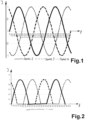
- Fig. 1 shows a normal current signal of a three-phase current, for example in a household.
- a three-phase current may be used, as has been explained before, to drive a multi-phase PM or, preferably, a BLDC motor.
- a motor can preferably be implemented in a domestic appliance such as a drive motor for a laundry drier or a washing machine, alternatively for a motor driving a pump, which may also be used in a washing machine or in a dishwasher.
- the invention allows for a better control of such motors with an easier generation of the current signals without any need for conventional shunt resistors, which shunt resistors basically have a negative enlarged electrical resistance leading to energy loss and unnecessary heat generation.
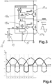
- a circuit with which this three-phase current may be operated and used for controlling and driving such a three-phase motor can be taken from Fig. 3 for a single switch device and Fig. 11 for a schematic circuit for the three-phase current.
- Fig. 2 shows only the positive signals of the three-phase current of Fig. 1 .
- These positive signals can be generated from the device of Fig. 3 , where the current is measured in relation to the voltage V IPH over the resistor R IPH .
- This resistor is designed as a small signal resistor, and the generated voltage signal may be used for digitization by a microcontroller of the control, which may be the microcontroller 15.
- a conventional shunt resistor is thus not needed, and the energy loss generated in the small signal resistor 13 is insignificant.
- the only major disadvantage is, as explained before, that only the positive signals can be generated at the resistor R IPH and used by the microcontroller 15.
- a field-oriented control FOC for any such three-phase motors mentioned above but needs of course the positive signals and the negative signals or, respectively, the complete current reading according to Fig. 1 .
- the special power semiconductors 17a and 17b for the high side and the low side may be high voltage N-channel power FREDFETs with the respective high side drivers 18a and 18b, wherein the low side driver is integrated into the microcontroller 15.
- These semiconductors 17a and 17b offer ultra-soft and ultra-fast diodes being ideally suited for hard switched inverter drivers, such as for three-phase motors.
- Both semiconductors 17a and 17b are self-supplied, thus eliminating the need for an external auxiliary power supply. They could be implemented in GaN-technology, alternatively in silicon technology or silicon carbide technology, respectively.
- Such GaN semiconductors provide a unique and instantaneous phase current output signal, which simplifies an implementation of a sensor-less control for a three-phase motor.
- An internal fault protection may include cycle-by-cycle current limiting for both power semiconductors 17a and 17b and also two-level thermal overload protection.
- An external system level monitoring may include a DC bus sensing means with four undervoltage levels and one overvoltage level. It may also include the option to drive external sensors such as an NTC temperature sensor for sensing high temperature at the switch device 11 or at a three-phase motor, respectively.
- Fig. 4 shows, with a division into six sectors each having the same size of 60°, how a part of the negative part of each phase may be generated, which is by adding the two positive parts of the other two phases and inverting it. However, this may be applied for the sectors S1, S2 and S3, which can thus be generated simply and exclusively from the measured current phases.
- the calculation according to the following formula is needed with using the sinus applied to the first phase in sector S2, applied to the second phase in sector S4 and applied to the third phase in sector S6.
- Fig. 6 now shows the measured positive current signals for the three current phases. It also shows, according to Fig. 4 , the measured and inverted negative parts. In addition, the angle according to which the sectors are divided is shown in dash-dotted line showing a rising ramp with a fall, and then rising again.
- Fig. 7 shows the combination of the current phase signals of Figs. 5 and 6 , where the complete current signals for all three current phases have been reconstructed, which give a picture similar to the one of Fig. 1 .
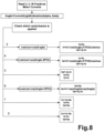
- Fig. 8 shows a flowchart for the algorithm for the method described before, but with a slight variation of how the calculation for some of the sectors S of Fig. 5 is done.
- the calculation needs to be done for the sectors S2, S4 and S6.
- the corresponding cosinus calculation is made together with a division. From a mathematical point of view, both calculations are equal.
- Fig. 9 is the basic concept
- Fig. 10 is the actual algorithm.
- the value Motor Omega we is estimated and gives the current feedback signal speed. This current feedback signal speed is used to get the real current angle. Finally, the real current speed (we) is used as well as the offset speed got on the PI speed, which is used to calculate the angle of the next current feedback loop.
- Fig. 11 shows one option using the circuit of Fig. 3 to form a circuit for a three-phase current control.
- a supervising control in the form of a separate microcontroller might be present to control the three switching devices 11a, 11b and 11c.
- Six semiconductor power components are needed.
- the resistors 13a, 13b and 13c are used to measure a voltage signal by conversion of an IPH current through the resistors into a voltage signal, which is then digitized and used by the low side controls.
- This circuit of Fig. 11 is used to calculate the current signals of Fig. 7 . Any of the trigonometric calculation methods described above can be used to calculate the current signals of Fig. 7 .
Landscapes
- Engineering & Computer Science (AREA)
- Power Engineering (AREA)
- Control Of Ac Motors In General (AREA)
Priority Applications (1)
| Application Number | Priority Date | Filing Date | Title |
|---|---|---|---|
| EP23382608.0A EP4482019A1 (de) | 2023-06-19 | 2023-06-19 | Verfahren und vorrichtung zum betreiben eines dreiphasenmotors mit dreiphasenstrom |
Applications Claiming Priority (1)
| Application Number | Priority Date | Filing Date | Title |
|---|---|---|---|
| EP23382608.0A EP4482019A1 (de) | 2023-06-19 | 2023-06-19 | Verfahren und vorrichtung zum betreiben eines dreiphasenmotors mit dreiphasenstrom |
Publications (1)
| Publication Number | Publication Date |
|---|---|
| EP4482019A1 true EP4482019A1 (de) | 2024-12-25 |
Family
ID=86904117
Family Applications (1)
| Application Number | Title | Priority Date | Filing Date |
|---|---|---|---|
| EP23382608.0A Withdrawn EP4482019A1 (de) | 2023-06-19 | 2023-06-19 | Verfahren und vorrichtung zum betreiben eines dreiphasenmotors mit dreiphasenstrom |
Country Status (1)
| Country | Link |
|---|---|
| EP (1) | EP4482019A1 (de) |
Citations (5)
| Publication number | Priority date | Publication date | Assignee | Title |
|---|---|---|---|---|
| US6316895B1 (en) * | 1999-09-01 | 2001-11-13 | Ramachandran Ramarathnam | Multi-speed motor controller |
| US20210172983A1 (en) * | 2019-12-10 | 2021-06-10 | Stmicroelectronics S.R.L. | Inverter and method for measuring phase currents in an electric machine |
| US20220149766A1 (en) * | 2020-11-11 | 2022-05-12 | Mando Corporation | Motor control device and method |
| US20220321045A1 (en) * | 2019-08-09 | 2022-10-06 | Festool Gmbh | Method for determining a rotor position of an electric motor of a power tool and power tool |
| US20220334155A1 (en) * | 2021-04-19 | 2022-10-20 | Infineon Technologies Ag | Voltage monitor using switching signal for motor |
-
2023
- 2023-06-19 EP EP23382608.0A patent/EP4482019A1/de not_active Withdrawn
Patent Citations (5)
| Publication number | Priority date | Publication date | Assignee | Title |
|---|---|---|---|---|
| US6316895B1 (en) * | 1999-09-01 | 2001-11-13 | Ramachandran Ramarathnam | Multi-speed motor controller |
| US20220321045A1 (en) * | 2019-08-09 | 2022-10-06 | Festool Gmbh | Method for determining a rotor position of an electric motor of a power tool and power tool |
| US20210172983A1 (en) * | 2019-12-10 | 2021-06-10 | Stmicroelectronics S.R.L. | Inverter and method for measuring phase currents in an electric machine |
| US20220149766A1 (en) * | 2020-11-11 | 2022-05-12 | Mando Corporation | Motor control device and method |
| US20220334155A1 (en) * | 2021-04-19 | 2022-10-20 | Infineon Technologies Ag | Voltage monitor using switching signal for motor |
Similar Documents
| Publication | Publication Date | Title |
|---|---|---|
| EP3876419B1 (de) | Entmagnetisierungserfassung für einen permanentmagnet-synchronmotorantrieb und verfahren | |
| US7839113B2 (en) | Apparatus and method for driving synchronous motor | |
| JP5259303B2 (ja) | インバータ装置 | |
| KR100732717B1 (ko) | 모터시스템 및 그 제어방법과, 이를 이용한 압축기 | |
| CN107112926B (zh) | 用于切换电机的运行状态的方法和用于切换电机的运行状态的设备 | |
| JP6217554B2 (ja) | インバータ装置 | |
| CN107112941B (zh) | 电力转换装置以及使用该电力转换装置的电力转向装置 | |
| US20210281207A1 (en) | System for detection and algorithmic avoidance of isolation failures in electric motors | |
| CN101312335B (zh) | 电动机驱动装置和电动机驱动控制方法 | |
| US8872457B2 (en) | Method and apparatus for driving a polyphase electronically commutated electric machine and a motor system | |
| JP6134813B2 (ja) | 電力変換装置および電力変換装置の制御方法 | |
| Azza et al. | Implementation of improved sliding mode observer and fault tolerant control for a PMSM drive | |
| KR20090089055A (ko) | 2상 영구자석 동기 전동기의 공간전압벡터 제어 장치 및방법 | |
| JP2016123194A (ja) | モータ駆動装置およびモータ駆動用モジュール並びに冷凍機器 | |
| RU2632916C1 (ru) | Переключающее устройство, устройство преобразования мощности, устройство возбуждения двигателя, нагнетатель воздуха, компрессор, кондиционер воздуха, холодильник и морозильный аппарат | |
| US11290036B2 (en) | Control device | |
| US12294320B2 (en) | Electric motor control device | |
| EP4482019A1 (de) | Verfahren und vorrichtung zum betreiben eines dreiphasenmotors mit dreiphasenstrom | |
| JP3638265B2 (ja) | 電力変換装置 | |
| CN104283474A (zh) | 具有异常检测功能的旋转电机控制装置 | |
| JP2004064864A (ja) | エレベータの制御装置 | |
| US11239760B2 (en) | Power conversion system and control method for voltage conversion circuit | |
| CN102714476B (zh) | 用于无刷直流电机的控制卡 | |
| Kanazawa et al. | Analysis of RMS current on DC-link capacitor with single-shunt current sensing system | |
| CN224124056U (zh) | 电动工具 |
Legal Events
| Date | Code | Title | Description |
|---|---|---|---|
| PUAI | Public reference made under article 153(3) epc to a published international application that has entered the european phase |
Free format text: ORIGINAL CODE: 0009012 |
|
| STAA | Information on the status of an ep patent application or granted ep patent |
Free format text: STATUS: THE APPLICATION HAS BEEN PUBLISHED |
|
| AK | Designated contracting states |
Kind code of ref document: A1 Designated state(s): AL AT BE BG CH CY CZ DE DK EE ES FI FR GB GR HR HU IE IS IT LI LT LU LV MC ME MK MT NL NO PL PT RO RS SE SI SK SM TR |
|
| STAA | Information on the status of an ep patent application or granted ep patent |
Free format text: STATUS: REQUEST FOR EXAMINATION WAS MADE |
|
| 17P | Request for examination filed |
Effective date: 20250624 |
|
| STAA | Information on the status of an ep patent application or granted ep patent |
Free format text: STATUS: THE APPLICATION HAS BEEN WITHDRAWN |
|
| 18W | Application withdrawn |
Effective date: 20260320 |