EP4483768A1 - Drahtloser reiniger und verfahren zum betrieb davon - Google Patents
Drahtloser reiniger und verfahren zum betrieb davon Download PDFInfo
- Publication number
- EP4483768A1 EP4483768A1 EP23857750.6A EP23857750A EP4483768A1 EP 4483768 A1 EP4483768 A1 EP 4483768A1 EP 23857750 A EP23857750 A EP 23857750A EP 4483768 A1 EP4483768 A1 EP 4483768A1
- Authority
- EP
- European Patent Office
- Prior art keywords
- brush device
- brush
- vacuum cleaner
- processor
- value
- Prior art date
- Legal status (The legal status is an assumption and is not a legal conclusion. Google has not performed a legal analysis and makes no representation as to the accuracy of the status listed.)
- Pending
Links
Images












Classifications
-
- A—HUMAN NECESSITIES
- A47—FURNITURE; DOMESTIC ARTICLES OR APPLIANCES; COFFEE MILLS; SPICE MILLS; SUCTION CLEANERS IN GENERAL
- A47L—DOMESTIC WASHING OR CLEANING; SUCTION CLEANERS IN GENERAL
- A47L9/00—Details or accessories of suction cleaners, e.g. mechanical means for controlling the suction or for effecting pulsating action; Storing devices specially adapted to suction cleaners or parts thereof; Carrying-vehicles specially adapted for suction cleaners
- A47L9/28—Installation of the electric equipment, e.g. adaptation or attachment to the suction cleaner; Controlling suction cleaners by electric means
- A47L9/2868—Arrangements for power supply of vacuum cleaners or the accessories thereof
- A47L9/2884—Details of arrangements of batteries or their installation
-
- A—HUMAN NECESSITIES
- A47—FURNITURE; DOMESTIC ARTICLES OR APPLIANCES; COFFEE MILLS; SPICE MILLS; SUCTION CLEANERS IN GENERAL
- A47L—DOMESTIC WASHING OR CLEANING; SUCTION CLEANERS IN GENERAL
- A47L5/00—Structural features of suction cleaners
- A47L5/12—Structural features of suction cleaners with power-driven air-pumps or air-compressors, e.g. driven by motor vehicle engine vacuum
- A47L5/22—Structural features of suction cleaners with power-driven air-pumps or air-compressors, e.g. driven by motor vehicle engine vacuum with rotary fans
- A47L5/24—Hand-supported suction cleaners
- A47L5/26—Hand-supported suction cleaners with driven dust-loosening tools
-
- A—HUMAN NECESSITIES
- A47—FURNITURE; DOMESTIC ARTICLES OR APPLIANCES; COFFEE MILLS; SPICE MILLS; SUCTION CLEANERS IN GENERAL
- A47L—DOMESTIC WASHING OR CLEANING; SUCTION CLEANERS IN GENERAL
- A47L9/00—Details or accessories of suction cleaners, e.g. mechanical means for controlling the suction or for effecting pulsating action; Storing devices specially adapted to suction cleaners or parts thereof; Carrying-vehicles specially adapted for suction cleaners
- A47L9/02—Nozzles
- A47L9/04—Nozzles with driven brushes or agitators
- A47L9/0405—Driving means for the brushes or agitators
- A47L9/0411—Driving means for the brushes or agitators driven by electric motor
-
- A—HUMAN NECESSITIES
- A47—FURNITURE; DOMESTIC ARTICLES OR APPLIANCES; COFFEE MILLS; SPICE MILLS; SUCTION CLEANERS IN GENERAL
- A47L—DOMESTIC WASHING OR CLEANING; SUCTION CLEANERS IN GENERAL
- A47L9/00—Details or accessories of suction cleaners, e.g. mechanical means for controlling the suction or for effecting pulsating action; Storing devices specially adapted to suction cleaners or parts thereof; Carrying-vehicles specially adapted for suction cleaners
- A47L9/28—Installation of the electric equipment, e.g. adaptation or attachment to the suction cleaner; Controlling suction cleaners by electric means
- A47L9/2805—Parameters or conditions being sensed
- A47L9/2826—Parameters or conditions being sensed the condition of the floor
-
- A—HUMAN NECESSITIES
- A47—FURNITURE; DOMESTIC ARTICLES OR APPLIANCES; COFFEE MILLS; SPICE MILLS; SUCTION CLEANERS IN GENERAL
- A47L—DOMESTIC WASHING OR CLEANING; SUCTION CLEANERS IN GENERAL
- A47L9/00—Details or accessories of suction cleaners, e.g. mechanical means for controlling the suction or for effecting pulsating action; Storing devices specially adapted to suction cleaners or parts thereof; Carrying-vehicles specially adapted for suction cleaners
- A47L9/28—Installation of the electric equipment, e.g. adaptation or attachment to the suction cleaner; Controlling suction cleaners by electric means
- A47L9/2805—Parameters or conditions being sensed
- A47L9/2831—Motor parameters, e.g. motor load or speed
-
- A—HUMAN NECESSITIES
- A47—FURNITURE; DOMESTIC ARTICLES OR APPLIANCES; COFFEE MILLS; SPICE MILLS; SUCTION CLEANERS IN GENERAL
- A47L—DOMESTIC WASHING OR CLEANING; SUCTION CLEANERS IN GENERAL
- A47L9/00—Details or accessories of suction cleaners, e.g. mechanical means for controlling the suction or for effecting pulsating action; Storing devices specially adapted to suction cleaners or parts thereof; Carrying-vehicles specially adapted for suction cleaners
- A47L9/28—Installation of the electric equipment, e.g. adaptation or attachment to the suction cleaner; Controlling suction cleaners by electric means
- A47L9/2836—Installation of the electric equipment, e.g. adaptation or attachment to the suction cleaner; Controlling suction cleaners by electric means characterised by the parts which are controlled
- A47L9/2847—Surface treating elements
-
- A—HUMAN NECESSITIES
- A47—FURNITURE; DOMESTIC ARTICLES OR APPLIANCES; COFFEE MILLS; SPICE MILLS; SUCTION CLEANERS IN GENERAL
- A47L—DOMESTIC WASHING OR CLEANING; SUCTION CLEANERS IN GENERAL
- A47L9/00—Details or accessories of suction cleaners, e.g. mechanical means for controlling the suction or for effecting pulsating action; Storing devices specially adapted to suction cleaners or parts thereof; Carrying-vehicles specially adapted for suction cleaners
- A47L9/28—Installation of the electric equipment, e.g. adaptation or attachment to the suction cleaner; Controlling suction cleaners by electric means
- A47L9/2857—User input or output elements for control, e.g. buttons, switches or displays
-
- A—HUMAN NECESSITIES
- A47—FURNITURE; DOMESTIC ARTICLES OR APPLIANCES; COFFEE MILLS; SPICE MILLS; SUCTION CLEANERS IN GENERAL
- A47L—DOMESTIC WASHING OR CLEANING; SUCTION CLEANERS IN GENERAL
- A47L9/00—Details or accessories of suction cleaners, e.g. mechanical means for controlling the suction or for effecting pulsating action; Storing devices specially adapted to suction cleaners or parts thereof; Carrying-vehicles specially adapted for suction cleaners
- A47L9/28—Installation of the electric equipment, e.g. adaptation or attachment to the suction cleaner; Controlling suction cleaners by electric means
- A47L9/2894—Details related to signal transmission in suction cleaners
-
- A—HUMAN NECESSITIES
- A47—FURNITURE; DOMESTIC ARTICLES OR APPLIANCES; COFFEE MILLS; SPICE MILLS; SUCTION CLEANERS IN GENERAL
- A47L—DOMESTIC WASHING OR CLEANING; SUCTION CLEANERS IN GENERAL
- A47L9/00—Details or accessories of suction cleaners, e.g. mechanical means for controlling the suction or for effecting pulsating action; Storing devices specially adapted to suction cleaners or parts thereof; Carrying-vehicles specially adapted for suction cleaners
- A47L9/28—Installation of the electric equipment, e.g. adaptation or attachment to the suction cleaner; Controlling suction cleaners by electric means
- A47L9/2889—Safety or protection devices or systems, e.g. for prevention of motor over-heating or for protection of the user
Definitions
- An embodiment of the disclosure relates to a cordless vacuum cleaner in which driving of a brush device is controlled, and an operating method of the cordless vacuum cleaner.
- a cordless vacuum cleaner is a type of electrically powered cleaner that is used by charging a battery included in the vacuum cleaner itself without having to connect a line to an outlet.
- the cordless vacuum cleaner includes a suction motor that generates suction power, and thus, may suck up foreign materials, such as dust, together with air, from a cleaner head or attachment (e.g., brush) through the suction power generated in the suction motor, and collect the sucked up foreign materials by separating the sucked up foreign materials from the air.
- Brushes of a cordless vacuum cleaner may be divided into a main brush generally used to clean a floor, and auxiliary brushes used for special purposes.
- Types of auxiliary brushes used for special purposes are being further subdivided to be applied to various cleaning environments.
- Various brushes may have different mechanical structures and may have different motor specifications (e.g., power consumption and suction power, brush rotational speed, etc.) and/or shapes. Accordingly, custom control suitable for characteristics of each brush is required, in order to improve the performance of each brush.
- a cordless vacuum cleaner includes a battery, a switch device used to supply power from the battery to a brush device connected to a cleaner body, a load detection sensor configured to detect a load of the brush device connected to the cleaner body, and at least one processor.
- the at least one processor may be configured to detect connection of the brush device to the cleaner body, based on at least one of a voltage value input to an input port of the at least one processor through a signal line or the load of the brush device.
- the at least one processor may be configured to identify a type of the brush device connected to the cleaner body.
- the at least one processor may be configured to determine a frequency for pulse width modulation (PWM) control corresponding to the identified type of the brush device.
- PWM pulse width modulation
- the at least one processor may be configured to control an operation of the switch device, based on the determined frequency.
- An operating method of a cordless vacuum cleaner includes detecting, by a load detection sensor, a load of a brush device connected to a cleaner body, detecting connection of the brush device to the cleaner body, based on at least one a voltage value input to an input port of at least one processor through a signal line or the load of the brush device, identifying a type of the brush device connected to the cleaner body, as the connection of the brush device to the cleaner body is detected, determining a frequency for pulse width modulation (PWM) control corresponding to the identified type of the brush device, and controlling an operation of a switch device used to supply power from a battery of the cleaner body to the brush device connected to the cleaner body.
- PWM pulse width modulation
- a cordless vacuum cleaner includes a cleaner body configured to receive a plurality of different types of brush devices configured to connect and disconnect to and from the cleaner body, each of the brush devices including a positive power line, a negative power line and a signal line; a switch device used to output power supplied from a battery according to an adjustable switching frequency; at least one processor.
- the at least one processor may be configured to identify a type of the brush device connected to the cleaner body based on an electrical connection of the signal line with respect to at least one of the positive power line and the negative power line; and adjust the switching frequency based on the identified type of brush device.
- the expression "at least one of a, b or c" indicates only a, only b, only c, both a and b, both a and c, both b and c, all of a, b, and c, or variations thereof.
- the expression "at least one of a, b or c" indicates only a, only b, only c, both a and b, both a and c, both b and c, all of a, b, and c, or variations thereof.
- a part includes or “comprises” an element, unless there is a particular description contrary thereto, the part may further include other elements, not excluding the other elements.
- the term such as “... unit” or “... module” used herein refers to a unit that performs at least one function or operation, and the unit may be implemented as hardware or software or as a combination of hardware and software.
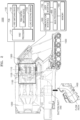
- FIG. 1 is a view for describing a cordless vacuum cleaner 100, according to an embodiment of the disclosure.
- the cordless vacuum cleaner 100 may refer to a vacuum cleaner that has a rechargeable battery therein and does not require a power cord to be connected to an electrical power outlet during cleaning.
- the cordless vacuum cleaner 100 is configured to operate using different vacuum heads or attachments.
- a given vacuum heads or attachment can be detachably connected or coupled to the cordless vacuum cleaner 100 and can be replaced with different types of vacuum heads or vacuum attachments.
- a user can manipulate the vacuum cleaner 100 so that an attachment such as a brush device 2000, for example, to suck up dust or foreign materials (e.g., dust, hair, trash, etc.) from a surface to be cleaned while moving the cordless vacuum cleaner 100 back and forth by using a handle mounted on a cleaner body 1000.
- the foreign materials sucked up from the surface to be cleaned through the brush device 2000 may be collected in a dust collection container (or referred to as a dust container) of the cleaner body 1000.
- a dust collection container or referred to as a dust container
- various brush-type devices are described herein, it should be appreciated that the present inventive teachings may be applied to other types of vacuum heads or attachments which can be detachably connected to the cordless vacuum cleaner 100 without departing from the scope of the invention.
- the cordless vacuum cleaner 100 may be a stick-type cleaner (sometimes referred to as a "wand" cleaner) including the cleaner body 1000, the brush device 2000, and an extension pipe 3000.
- a stick-type cleaner sometimes referred to as a "wand” cleaner
- the cordless vacuum cleaner 100 may include more or fewer components than those illustrated in FIG. 1 .
- the cordless vacuum cleaner 100 may include the cleaner body 1000 and the brush device 2000 without the extension pipe 3000.
- the cordless vacuum cleaner 100 may further include a station (not shown) for discharging dust from the cleaner body 1000 and charging the battery.
- the cleaner body 1000 may include a suction motor configured to form a vacuum in the cordless vacuum cleaner 100, and a dust collection container (dust container) in which foreign materials sucked up from a surface to be cleaned are accommodated (e.g., a floor, bedding, or a sofa), and is a portion moved by being held by the user during cleaning.
- the cleaner body 1000 may further include, but is not limited to, a switch device 1133 for controlling power supply from the battery 1500 to the brush device 2000 connected to the cleaner body 1000, a load detection sensor 1134 for detecting a load of the brush device 2000 connected to the cleaner body 1000, and at least one processor 1001.
- a switch device 1133 for controlling power supply from the battery 1500 to the brush device 2000 connected to the cleaner body 1000
- a load detection sensor 1134 for detecting a load of the brush device 2000 connected to the cleaner body 1000
- the brush device 2000 is a device configured to suck up air and foreign materials of a surface to be cleaned by being pressed against the surface to be cleaned.
- the brush device 2000 may also be referred to as a cleaner head or attachment.
- the brush device 2000 may be rotatably coupled to the extension pipe 3000.
- the brush device 2000 may include, but is not limited to, a motor and a drum to which a rotating brush is attached.
- the brush device 2000 may further include at least one processor configured to control communication with the cleaner body 1000.
- a type of the brush device 2000 may vary.
- the brush device 2000 may include, but is not limited to, a general brush (a hard floor brush), a carpet brush, a bedding brush, a pet brush, and a wet brush according to usage. Different types of brush devices 2000 may have different maximum motor outputs and may require different electrical inputs according to characteristics of applications. A type of the brush device 2000 will be described below in more detail with reference to FIG. 4 .
- the extension pipe 3000 may be formed as a hollow pipe. In some embodiments, the extension pipe 3000 has a certain rigidity. In some embodiments, the extension pipe 3000 may be formed as a flexible hose. The extension pipe 3000 may be configured to transmit suction power generated through the suction motor of the cleaner body 1000 to the brush device 2000, and move air and foreign materials sucked up through the brush device 2000 to the cleaner body 1000. The extension pipe 3000 may be detachably connected to the brush device 2000. The extension pipe 3000 may be formed in multiple stages between the cleaner body 1000 and the brush device 2000. There may be two or more extension pipes 3000.
- each of the cleaner body 1000, the brush device 2000, and the extension pipe 3000 included in the cordless vacuum cleaner 100 may include power lines (e.g., a positive (+) power line and a negative (-) power line) and a signal line.
- the power lines may be lines for transmitting power supplied from a battery 1500 to the cleaner body 1000 and the brush device 2000 connected to the cleaner body 1000.
- the signal line is different from the power lines, and may be a line for transmitting and receiving a signal between the cleaner body 1000 and the brush device 2000.
- the signal line may be implemented to be connected to the power lines in the brush device 2000.
- a voltage supplied from the battery 150 tends to decrease as the battery 1500 is discharged. Accordingly, when the battery 1500 is charged to 100%, the drum of the brush device 2000 rotates rapidly, but as a charge amount of the battery 1500 decreases, the drum of the brush device 2000 may rotate slowly. That is, revolutions per minute (RPM) of the drum of the brush device 2000 is not kept constant, but as a cleaning time elapses, a voltage of the battery 1500 drops and RPM of the drum of the brush device 2000 (hereinafter, referred to as drum RPM) decreases.
- RPM revolutions per minute
- the cordless vacuum cleaner 100 may include the switch device 1133 for pulse width modulation (PWM) control (hereinafter, referred to as a PWM control switch device).
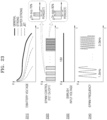
- PWM control may refer to a control method in which average power per unit time is input to the brush device 2000 by periodically repeating a power supply interval (ON interval) and a power cutoff interval (OFF interval).
- the average power per unit time input to the brush device 2000 may vary according to a duty value.
- the duty value may refer to a duty cycle or a duty ratio of a pulse width when a period is constant.
- the duty value may refer to a ratio of a power transmission interval (hereinafter, referred to as an on-duty interval) within a single period. Because a total time for current to flow through the motor of the brush device 2000 increases as the duty value increases, average power supplied to the brush device 2000 may increase.
- the cleaner body 1000 may perform control to compensate for a decrease in the drum RPM of the brush device 2000 by increasing the duty value (i.e., an interval where the switch device 1133 is turned on and power is supplied to the brush device 2000) as the voltage of the battery 1500 is reduced.
- the cleaner body 1000 may maintain the duty value at about 72% for a certain period of time after starting cleaning, and then may gradually increase the duty value according to a voltage drop of the battery 1500 to 95%.
- an average voltage input to the brush device 2000 (hereinafter, referred to as an input voltage of the brush device 2000) may be maintained constant.
- a voltage e.g., 18 V
- the cordless vacuum cleaner 100 may appropriately increase the duty ratio during a cleaning operation, thereby maintaining constant drum RPM of the brush device 2000.
- a frequency for PWM control hereinafter, referred to as a PWM frequency
- a PWM frequency may be fixed.
- the fixed PWM frequency is a high frequency
- loss of the PWM control switch device 1133 may increase (e.g., heat generation, component stress, and switching noise may increase) as the number of switching increases, thereby shortening a usage time of the cordless vacuum cleaner 100.
- the fixed PWM frequency is too low, problems may occur in driving and controlling the brush de vice 2000.
- abnormal noise or abnormal vibration may occur.
- a type of the brush device 2000 may vary, and different types of brush devices 2000 may have different mechanical structures or motor specifications (e.g., power consumption and shapes). Accordingly, when the cordless vacuum cleaner 100 uses the same PWM frequency regardless of a type of the brush device 2000, abnormal noise or abnormal vibration may increase in a specific brush device.
- the cordless vacuum cleaner 100 may identify a type of the brush device 2000 connected by the user, and may differently select a frequency for PWM control according to the type of the brush device 2000, to improve the motor efficiency of the brush device 2000 and reduce abnormal noise and abnormal vibration (avoid resonance).
- the cordless vacuum cleaner 100 may select a first frequency as a PWM frequency; when the brush device 2000 connected to the cleaner body 1000 is a B-type brush device 20, the cordless vacuum cleaner 100 may select a second frequency as a PWM frequency; and when the brush device 2000 connected to the cleaner body 1000 is a C-type brush device 30, the cordless vacuum cleaner 100 may select a third frequency as a PWM frequency.
- the first frequency may be a frequency in which characteristics (e.g., a motor output and a resonance point) of the A-type brush device 10 are reflected
- the second frequency may be a frequency in which characteristics (e.g., a motor output and a resonance point) of the B-type brush device 20 are reflected
- the third frequency may be a frequency in which characteristics (e.g., a motor output and a resonance point) of the C-type brush device 30 are reflected.
- the C-type brush device 30 is a light load (or low load) brush device (a brush device with a low maximum motor output)
- switching loss and electrical noise may be reduced by selecting the third frequency lower than the first frequency as a PWM frequency.
- the third frequency may be a frequency at which abnormal noise or abnormal vibration does not occur when the C-type brush device 30 is driven.
- the cordless vacuum cleaner 100 may adjust other parameters related to PWM control in addition to a PWM frequency according to a type of the brush device 2000.
- the cordless vacuum cleaner 100 may determine an input voltage, a trip level, etc. of the brush device 2000 in addition to a PWM frequency, according to a type of the brush device 2000 connected to the cleaner body 1000.
- An input voltage of the brush device 2000 may be an average voltage per unit time to be supplied to the brush device 2000.
- a trip level may serve as a fault protection technique for preventing an overload of the brush device 2000 may include a reference load value (e.g., a reference current value) that serves as a condition for stopping an operation of the brush device 2000.
- a reference load value e.g., a reference current value
- the cordless vacuum cleaner 100 may adjust parameters related to PWM control by reflecting an actual load value of the brush device 2000 connected to the cleaner body 1000, a suction power strength of the cleaner body 1000, or a voltage drop of the battery 1500.
- An operation in which the cordless vacuum cleaner 100 adjusts parameters related to PWM control according to a type of the brush device 2000, an actual load value of the brush device 2000, a suction power strength of the cleaner body 1000, or a voltage drop of the battery 1500 will be described below in detail with reference to FIGS. 12 to 23 .
- a configuration of the cleaner body 1000 in which power supply to the brush device 2000 is controlled according to a type of the brush device 2000 connected by the user will be described with reference to FIG. 2 .
- FIG. 2 is a view for describing the cleaner body 1000, according to an embodiment of the disclosure.
- the cleaner body 1000 may include a suction power generating device (hereinafter, referred to as a motor assembly 1100) for generating suction power required to suck up foreign materials located on a surface to be cleaned, a dust collection container 1200 (also referred to as a dust container) in which the foreign materials sucked up from the surface to be cleaned are accommodated, a filter unit 1300, a pressure sensor 1400, the battery 1500 for supplying power to the motor assembly 1100, a communication interface 1600, a user interface 1700, at least one processor 1001 (e.g., a main processor 1800 and a first processor 1131), and a memory 1900.
- a main processor 1800 and a first processor 1131 e.g., a main processor 1800 and a first processor 1131
- the cleaner body 1000 may include more or fewer components than those illustrated in FIG. 2 .
- the motor assembly 1100 may include a suction motor 1110 configured to convert an electric force in to a mechanical rotational force, a fan 1120 (or an impeller) that is rotatably coupled to the suction motor 1110, and a printed circuit board (PCB) 1130 connected to the suction motor 1110. Operation of the suction motor 1110 and the fan 1120 establish a vacuum in the cordless vacuum cleaner 100.
- the vacuum refers to a state lower than atmospheric pressure.
- the suction motor 1110 may include, but is not limited to, a brushless direct current (BLDC) motor.
- BLDC brushless direct current
- the PCB 1130 may include, but is not limited to, a processor (hereinafter, the first processor 1131) configured to control the suction motor 1110 and control communication with the brush device 2000, a first switch device 1132 connected to a signal line, a switch device (hereinafter, referred to as a PWM control switch device 1133) configured to control power supply to the brush device 2000, and a load detection sensor 1134 configured to detect a load of the brush device 2000.
- the PWM control switch device 1133 may include, but is not limited to, a transistor such as, for example, a field-effect transistor (FET), a Bipolar junction transistor (BJT), or an insulated gate bipolar transistor (IGBT).
- FET field-effect transistor
- BJT Bipolar junction transistor
- IGBT insulated gate bipolar transistor
- the load detection sensor 1134 may include, but is not limited to, a shunt resistor, a shunt resistor in combination with an amplification circuit (operational amplifier (OP-AMP)), a current detection sensor, or a magnetic field detection sensor (non-contact manner).
- a shunt resistor in combination with an amplification circuit (operational amplifier (OP-AMP)
- OP-AMP operational amplifier
- current detection sensor current detection sensor
- magnetic field detection sensor non-contact manner
- the first processor 1131 may be configured to obtain data (hereinafter, referred to as state data) related to a state of the suction motor 1110, and transmit the state data of the suction motor 1110 to the main processor 1800. Also, the first processor 1131 may be configured to transmit a signal (hereinafter, a first signal) to the brush device 2000 through the signal line by controlling (e.g., turning on or off) an operation of the first switch device 1132 connected to the signal line.
- the first switch device 1132 is a device that enables a state of the signal line to become low. For example, the first switch device 1132 is a device that enables a voltage of the signal line to be 0 V.
- the first signal may include, but is not limited to, data indicating at least one of target RPM of a rotating brush of the brush device 2000 (hereinafter, also referred to as target drum RPM), a target trip level of the brush device 2000, or power consumption of the suction motor 1110.
- the first signal may include data for controlling an illumination device included in the brush device 2000.
- the first signal may be implemented with a pre-set number of bits.
- the first signal may be implemented with 5 bits or 8 bits, and have a transmission period of 10 ms per bit, but an embodiment of the disclosure is not limited thereto.
- the first processor 1131 may be configured to detect a signal (hereinafter, a second signal) transmitted from the brush device 2000 through the signal line.
- the second signal may include, but is not limited to, data indicating a current state of the brush device 2000.
- the second signal may include data on a current operation condition (e.g., current drum RPM, a current trip level, and a current illumination device setting value).
- the second signal may further include data indicating a type of the brush device 2000.
- the first processor 1131 may be configured to transmit, to the main processor 1800, the data indicating the current state of the brush device 2000 or the data indicating the type of the brush device 2000, included in the second signal.
- the motor assembly 1100 may be located in the dust collection container (dust container) 1200.
- the dust collection container 1200 may be configured to filter out dust or dirt in air introduced through the brush device 2000, and collect the same.
- the dust collection container 1200 may be provided to be attached to or detached from the cleaner body 1000.
- the dust collection container 1200 may collect foreign materials through a cyclone method of separating the foreign materials by using a centrifugal force.
- the air from which the foreign materials are removed through the cyclone method may be discharged out of the cleaner body 1000, and the foreign materials may be contained in the dust collection container 1200.
- a multi-cyclone may be located in the dust collection container 1200.
- the dust collection container 1200 may be provided so that the foreign materials are collected below the multi-cyclone.
- the dust collection container 1200 may include a dust collection container door (also referred to as a door of the dust container 1200) provided so that the dust collection container 1200 is opened when connected to a station.
- the dust collection container 1200 may include a first dust collecting portion where relatively large foreign materials collected primarily are collected, and a second dust collecting portion where relatively small foreign materials collected by the multi-cyclone are collected.
- the first dust collecting portion and the second dust collecting portion may both be provided to be externally opened when the dust collection container door is opened.
- the filter unit 1300 may filter out fine particulate matters and the like, which are not filtered out by the dust collection container 1200.
- the filter unit 1300 may include a discharge port for discharging the air that passed through a filter to the outside of the cordless vacuum cleaner 100.
- the filter unit 1300 may include, but is not limited to, a motor filter or a high-efficiency particulate air (HEPA) filter.
- HEPA high-efficiency particulate air
- the pressure sensor 1400 may measure pressure in a flow path (hereinafter, also referred to as flow path pressure).
- the pressure sensor 1400 provided at a suction end (e.g., a suction duct 40) may measure a flow rate change at a corresponding location by measuring static pressure.
- the pressure sensor 1400 may include, but is not limited to, an absolute pressure sensor or a relative pressure sensor.
- the main processor 1800 may sense a first pressure value before the suction motor 1110 is operated, by using the pressure sensor 1400. Then, the main processor 1800 may sense a second pressure value after the suction motor 1110 is operated at the target RPM, and use a difference between the first pressure value and the second pressure value as a pressure value in the flow path.
- the first pressure value may be a pressure value according to internal/external influences, such as the weather, an altitude, a state of the cordless vacuum cleaner 100, and an amount of dust inflow
- the second pressure value may be a pressure value according to an operation of the suction motor 1110 and the pressure value according to the internal/external influences, such as the altitude, the state of the cordless vacuum cleaner 100, and the amount of dust inflow
- the difference between the first pressure value and the second pressure value may be the pressure value according to an operation of the suction motor 1110. Accordingly, when the difference between the first pressure value and the second pressure value is used as the pressure value in the flow path, the internal/external influence other than the suction motor 1110 may be reduced.
- the flow path pressure measured by the pressure sensor 1400 may be used to identify a current usage environment state of the brush device 2000 (e.g., a state of the surface to be cleaned (a hard floor, a carpet, a mat, or a corner) or a state of being lifted from the surface to be cleaned), and may be used to measure suction power that changes according to a contamination degree or a dust collected degree of the dust collection container 1200.
- a current usage environment state of the brush device 2000 e.g., a state of the surface to be cleaned (a hard floor, a carpet, a mat, or a corner) or a state of being lifted from the surface to be cleaned
- suction power that changes according to a contamination degree or a dust collected degree of the dust collection container 1200.
- the pressure sensor 1400 may be located at the suction end (e.g., the suction duct 40).
- the suction duct 40 may be a structure that connects the dust collection container 1200 and the extension pipe 3000 to each other or the dust collection container 1200 and the brush device 2000 to each other so that a fluid including the foreign materials may move to the dust collection container 1200.
- the pressure sensor 1400 may be located at an end of a straight portion (or an inflection point of the straight portion and a curved portion) of the suction duct 40, but an embodiment of the disclosure is not limited thereto.
- the pressure sensor 1400 may be located at a center of the straight portion of the suction duct 40. Meanwhile, when the pressure sensor 1400 is located at the suction duct 40, the pressure sensor 1400 is located at a front end of the suction motor 1110 that generates suction power, and thus, the pressure sensor 1400 may be implemented as a negative pressure sensor.
- the pressure sensor 1400 is located at the suction duct 40, but an embodiment of the disclosure is not limited thereto.
- the pressure sensor 1400 may be located at a discharge port (e.g., in the motor assembly 1100). When the pressure sensor 1400 is located at the discharge port, the pressure sensor 1400 is located at a rear end of the suction motor 1110, and thus, the pressure sensor 1400 may be implemented as a positive pressure sensor. Also, a plurality of the pressure sensors 1400 may be provided in the cordless vacuum cleaner 100.
- the battery 1500 may be detachably connected on the cleaner body 1000.
- the battery 1500 may be electrically connected to a charging terminal provided at the station.
- the battery 1500 may be charged by receiving power from the charging terminal.
- the cleaner body 1000 may include the communication interface 1600 for performing communication with an external device.
- the cleaner body 1000 may communicate with the station (or a server device 300) through the communication interface 1600.
- the communication interface 1600 may include a short-range wireless communication interface and a long-range wireless communication interface.
- Examples of the short-range wireless communication interface may include, but are not limited to, a Bluetooth communication interface, a Bluetooth low energy (BLE) communication interface, a near-field communication (NFC) interface, a wireless local area network (WLAN) (Wi-Fi) communication interface, a Zigbee communication interface, an infrared data association (IrDA) communication interface, a Wi-Fi direct (WFD) communication interface, an ultra-wideband (UWB) communication interface, and an Ant+ communication interface.
- BLE Bluetooth low energy
- NFC near-field communication
- Wi-Fi wireless local area network
- Zigbee communication interface an infrared data association (IrDA) communication interface
- Wi-Fi direct (WFD) communication interface an
- the user interface 1700 may be provided at the handle.
- the user interface 1700 may include an input interface and an output interface.
- the cleaner body 1000 may receive a user input related to an operation of the cordless vacuum cleaner 100 or output information related to an operation of the cordless vacuum cleaner 100, through the user interface 1700.
- the cleaner body 1000 may output information about a docking state, information about a state of the dust container 1200, and information about a state of a dust bag through the user interface 1700.
- Examples of the input interface may include a power button and a suction power strength adjusting button.
- Examples of the output interface may include, but are not limited to, a light-emitting diode (LED) display, a liquid-crystal display (LCD), a touch screen, and a speaker.
- LED light-emitting diode
- LCD liquid-crystal display
- touch screen and a speaker.
- the cleaner body 1000 may include at least one processor 1001.
- the cleaner body 1000 may include one processor or a plurality of processors.
- the cleaner body 1000 may include the main processor 1800 connected to the user interface 1700 and the first processor 1131 connected to the suction motor 1110.
- the at least one processor 1001 may control an overall operation of the cordless vacuum cleaner 100.
- the at least one processor 1001 may determine power consumption (suction power strength) of the suction motor 1110, drum RPM of the brush device 2000, and a trip level of the brush device 2000.
- the at least one processor 1001 may detect connection of the brush device 2000 to the cleaner body 1000, through the load detection sensor 1134.
- the at least one processor 1001 may identify a type of the brush device 2000 connected to the cleaner body 1000.
- the at least one processor 1001 may identify a type of the brush device, based on a voltage value input through the signal line.
- the at least one processor 1001 may identify a brush device having an identification resistor corresponding to a voltage value input through the signal line from among a plurality of types, when the voltage value input through the signal line is between a maximum input voltage value and a minimum input voltage value.
- the at least one processor 1001 may identify a type of the brush device 2000, based on a change in a voltage value input to an input port according to an operation (ON/OFF) state of the switch device 1133, when the voltage value input through the signal line is the maximum input voltage value or the minimum input voltage value.
- the at least one processor 1001 may determine a frequency for pulse width modulation (PWM) control (PWM frequency) corresponding to the identified type of the brush device 2000.
- PWM frequency pulse width modulation
- the at least one processor 1001 may control an operation of the switch device 1133, based on the determined PWM frequency.
- the at least one processor 1001 may include at least one of a central processing unit (CPU), a graphics processing unit (GPU), an accelerated processing unit (APU), a many integrated core (MIC), a digital signal processor (DSP), or a neural processing unit (NPU).
- the at least one processor 1001 may be implemented in the form of an integrated system-on-chip (SoC) including one or more electronic components.
- SoC system-on-chip
- the at least one processor 1001 may each be implemented as separate hardware (H/W).
- the at least one processor 1001 may be referred to as a microprocessor controller (MICOM), a micro-processor unit (MPU), or a micro-controller unit (MCU).
- MICOM microprocessor controller
- MPU micro-processor unit
- MCU micro-controller unit
- the at least one processor 1001 may be implemented as a single core processor or a multicore processor.
- the memory 1900 may store programs for processes and control by the at least one processor 1001, or may store input/output data.
- the memory 1900 may store a pre-trained artificial intelligence (Al) model (e.g., a support vector machine (SVM) algorithm), state data of the suction motor 1110, a measurement value of the pressure sensor 1400, state data of the battery 1500, state data of the brush device 2000, error occurrence data (failure history data), power consumption of the suction motor 1110 corresponding to an operation condition, RPM of a drum with a rotating brush, a trip level, an operation sequence of the suction motor 1110 corresponding to a suction power generation pattern, a type of the brush device 2000 corresponding to a voltage value input through the signal line, a PWM frequency for each type of the brush device 2000, an average input voltage for each type of the brush device 2000, and a high load reference value (low load reference value) for each type of the brush device 2000.
- Al artificial intelligence
- SVM support vector machine
- the high load reference value may be a reference value for determining a state of the brush device 2000 as a high load state
- the low load reference value may be a reference load value for determining a state of the brush device 2000 as a low load state.
- the high load reference value and the low load reference value may vary according to a type of the brush device 2000, a suction power strength, and a suction power mode.
- the memory 1900 may include an external memory and an internal memory.
- the memory 1900 may include at least one type of storage medium from among a flash memory type, a hard disk type, a multimedia card micro type, a card type memory (e.g., an SD or XD memory), a random-access memory (RAM), a static random-access memory (SRAM), a read-only memory (ROM), an electrically erasable programmable read-only memory (EEPROM), a programmable read-only memory (PROM), a magnetic memory, a magnetic disk, and an optical disk.
- Programs stored in the memory 1900 may be classified into a plurality of modules according to their functions.
- FIG. 3 is a view for describing operations of processors of the cordless vacuum cleaner 100, according to an embodiment of the disclosure.
- the main processor 1800 may identify states of components in the cordless vacuum cleaner 100 by communicating with the battery 1500, the pressure sensor 1400, and the first processor 1131 in the motor assembly 1100.
- the main processor 1800 may communicate with each component by using, but not limited to, universal asynchronous receiver/transmitter (UART) communication or inter-integrated circuit (I2C) communication.
- UART universal asynchronous receiver/transmitter
- I2C inter-integrated circuit
- the main processor 1800 may obtain, from the battery 1500 by using UART communication, data on a voltage state (e.g., normal, abnormal, fully charged, fully discharged, charge voltage, or charge amount) of the battery 1500.
- the main processor 1800 may obtain, from the pressure sensor 1400 by using I2C communication, data on flow path pressure.
- the main processor 1800 may obtain, from the first processor 1131 connected to the suction motor 1110 by using UART communication, data on suction power strength, RPM of the suction motor 1110, and a state (e.g., normal or abnormal) of the suction motor 1110.
- Suction power is an electric force consumed to operate the cordless vacuum cleaner 100, and may be referred to as power consumption.
- the main processor 1800 may obtain, from the first processor 1131, data related to a load of the brush device 2000 and data on a type of the brush device 2000.
- the first processor 1131 may obtain, from the brush device 2000 through signal line communication with a second processor 2410 of the brush device 2000, state data (e.g., drum RPM, a trip level, normal, or abnormal) of the brush device 2000.
- the first processor 1131 may transmit state data of the brush device 2000 to the main processor 1800 through UART communication.
- the first processor 1131 may transmit, to the main processor 1800, state data of the suction motor 1110 and the state data of the brush device 2000 at different intervals.
- the first processor 1131 may transmit the state data of the suction motor 1110 to the main processor 1800 every 0.02 seconds, and transmit the state data of the brush device 2000 to the main processor 1800 every 0.2 seconds, but an embodiment of the disclosure is not limited thereto.
- the main processor 1800 may determine whether an error occurs based on states of components in the cordless vacuum cleaner 100, a state of the suction motor 1110, and a state of the brush device 2000, and may periodically transmit, to the station, data related to the occurrence of the error through short-range wireless communication (e.g., BLE communication).
- short-range wireless communication e.g., BLE communication
- the first processor 1131 of the cleaner body 1000 and the second processor 2410 of the brush device 2000 are connected to each other through UART communication or I2C communication, a high impedance effect caused by an internal line of the extension pipe 3000, and damaging of a circuit device (e.g., a maximum value excess of a MICOM AD port) caused by electrostatic discharge (ESD) and/or an over voltage may become issues. Accordingly, according to an embodiment of the disclosure, the first processor 1131 of the cleaner body 1000 and the second processor 2410 of the brush device 2000 communicate with each other through signal line communication instead of UART communication or I2C communication.
- a circuit for signal line communication may include a voltage distributing circuit (hereinafter, referred to as a voltage distributer) to prevent the damaging of the circuit device caused by over voltage, power noise, surge, electrical overstress (ESD), or electrical discharge (EOS), etc.
- a voltage distributer a voltage distributing circuit
- ESD electrical overstress
- EOS electrical discharge
- communication between the first processor 1131 of the cleaner body 1000 and the second processor 2410 of the brush device 2000 is not limited to signal line communication.
- the first processor 1131 of the cleaner body 1000 and the second processor 2410 of the brush device 2000 may communicate with each other through UART communication or I2C communication.
- the noise reduction circuit may include at least one of, but not limited to, a low-pass filter, a high-pass filter, a band-pass filter, a damping resistor, or a distribution resistor.
- the first processor 1131 of the cleaner body 1000 and the second processor 2410 of the brush device 2000 may communicate with each other through UART communication or I2C communication. For convenience of explanation, the following will be described assuming that the cleaner body 1000 and the brush device 2000 communicate with each other through signal line communication.
- the main processor 1800 may receive a user input on a setting button (e.g., an ON/OFF button or a +/- setting button) included in the user interface 1700 or control an output of an LCD.
- the main processor 1800 may identify a usage environment state (e.g., a state of a surface to be cleaned (a hard floor, a carpet, a mat, or a corner) and a state of being lifted from the surface to be cleaned), by using a pre-trained AI model (e.g., a SVM algorithm), and determine operation information (e.g., power consumption, drum RPM, or a trip level of the suction motor 1110) of the cordless vacuum cleaner 100 suitable for the usage environment state of the brush device 2000.
- a usage environment state e.g., a state of a surface to be cleaned (a hard floor, a carpet, a mat, or a corner) and a state of being lifted from the surface to be cleaned
- a pre-trained AI model e.g., a S
- the main processor 1800 may transmit, to the first processor 1131, the operation information of the cordless vacuum cleaner 100 suitable for the usage environment state of the brush device 2000.
- the first processor 1131 may adjust the strength of suction power (power consumption or RPM) of the suction motor 1110 according to the operation information of the cordless vacuum cleaner 100, and transmit the operation information of the cordless vacuum cleaner 100 suitable for the usage environment state of the brush device 2000, to the second processor 2410 through signal line communication.
- the second processor 2410 may adjust drum RPM, a trip level, and an illumination device (e.g., an LED display) according to the operation information of the cordless vacuum cleaner 100.
- the brush device 2000 will be described in more detail with reference to FIG. 4 .
- FIG. 4 is a view for describing the brush device 2000, according to an embodiment of the disclosure.
- the brush device 2000 may include, but is not limited to, a motor 2100, a drum 2200 to which a rotating brush is attached, and an illumination device 2300.
- the motor 2100 of the brush device 2000 may be provided in the drum 2200 or outside the drum 2200.
- the drum 2200 may receive power from the motor 2100 through a belt.
- the motor 2100 may be a planet geared motor.
- the planet geared motor may include a planet gear 2101 that is coupled to a direct current (DC) motor.
- the planet gear 2101 adjusts RPM of the drum 2200 according to a gear ratio.
- RPM of the motor 2100 and RPM of the drum 2200 may have a constant ratio.
- the motor 2100 may be, but is not limited to, a brushless direct current (BLDC) motor.
- BLDC brushless direct current
- the illumination device 2300 lights up a dark surface to be cleaned, lights up dust or foreign materials of the surface to be cleaned to be easily identified, or indicates a state of the brush device 2000, and may be provided in front of or at the top of the brush device 2000.
- the illumination device 2300 may include, but is not limited to, an LED display.
- the illumination device 2300 may be a laser.
- the illumination device 2300 may automatically operate when the motor 2100 operates, or may operate according to control by the second processor 2410. According to an embodiment of the disclosure, the illumination device 2300 may change a color or brightness according to control by the second processor 2410.
- the brush device 2000 may further include a PCB 2400.
- the PCB 2400 may include a circuit for signal line communication with the cleaner body 1000.
- the PCB 2400 may include, but is not limited to, the second processor 2410, a switch device (hereinafter, also referred to as a second switch device) (not shown) connected to a signal line, and an identification (ID) resistor (not shown) indicating a type of the brush device 2000.
- a switch device hereinafter, also referred to as a second switch device
- ID identification resistor
- a type of the brush device 2000 may vary.
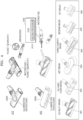
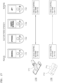
- the brush device 2000 may include, but is not limited to, a multi-brush 401, a hard floor brush 402, a wet brush 403, a turbo (carpet) brush 404, a bedding brush 405, and a pet brush 406. Additional brushes types may also include, but are not limited to, a bristle brush (not shown), and a gap brush (not shown).
- the brush device 2000 may include a light load (or low load) brush having a relatively low maximum motor output and a high load brush having a relatively high maximum motor output.
- the brush device 2000 may include a first type of brush device including an ID resistor, a second type of brush device in which the signal line is short-circuited to a + power line, a third type of brush device in which the signal line is short-circuited to a - power line, and a fourth type of brush device in which the signal line is open.
- a first type of brush device including an ID resistor a second type of brush device in which the signal line is short-circuited to a + power line
- a third type of brush device in which the signal line is short-circuited to a - power line
- a fourth type of brush device in which the signal line is open.
- the cleaner body 1000 may distinguish a type of the brush device 2000 based on an input voltage value detected through the signal line.
- the cleaner body 1000 may distinguish a type of the brush device 2000 based on a data signal transmitted from the brush device 2000.
- the brush device 2000 may transmit a data signal including information indicating a type of the brush device 2000 to the cleaner body 1000.
- FIG. 5 is a view for describing a first type of brush device 2001 including an ID resistor 2500, according to an embodiment of the disclosure.
- the first type of brush device 2001 may be designed to include the ID resistor 2500.
- the ID resistor 2500 indicates a type of the brush device 2000 and may vary according to the type of brush device 2000.
- the ID resistor 2500 of the multi-brush 401 may be 330 K ⁇
- the ID resistor 2500 of the hard floor brush 402 may be 2.2 M ⁇
- the ID resistor 2500 of the turbo (carpet) brush 404 may be 910 K ⁇ , but an embodiment of the disclosure is not limited thereto.
- the voltage value input to the input port of the first processor 1131 may decrease when a value of the ID resistor 2500 increases.
- the first processor 1131 may identify a type of the brush device 2000 corresponding to the ID resistor 2500, based on the voltage value input to the input port. For example, the first processor 1131 may identify the first type of brush device 2001 including the ID resistor 2500 corresponding to the input voltage value from among a plurality of ID resistors as the brush device 2000 connected to the cleaner body 1000.
- the ID resistor 2500 will be described in more detail with reference to FIG. 6 .
- FIG. 6 is a diagram for describing the ID resistor 2500 of the brush device 2000, according to an embodiment of the disclosure.
- an ID resistor of the multi-brush 401 may be 330 K ⁇
- an ID resistor of the hard floor brush 402 may be 2.2 M ⁇
- an ID resistor of the turbo (carpet) brush 404 may be 910 K ⁇ .
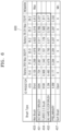
- the voltage value input to the input port of the first processor 1131 may be 2.785 V when the multi-brush 401 is connected to the cordless vacuum cleaner 100, the voltage value input to the input port of the first processor 1131 may be 0.791 V when the hard floor brush 402 is connected to the cordless vacuum cleaner 100, and the voltage value input to the input port of the first processor 1131 may be 1.563 V when the turbo (carpet) brush 404 is connected to the cordless vacuum cleaner 100.
- the first processor 1131 may identify that the multi-brush 401 is connected when the voltage value input to the input port is 2.785 V, identify that the hard floor brush 402 is connected when the voltage value input to the input port is 0.791 V, and identify that the turbo (carpet) brush 404 is connected when the voltage value input to the input port is 1.563 V.
- the first processor 1131 may transmit information about the type of the brush device 2000 to the main processor 1800.
- an input voltage value varies below 3.3 V (or 5.0 V) according to an ID resistor value of the first type of brush device 2001 including the ID resistor 2500. Because an interval between input voltage values according to ID resistor values decreases as the number of first type of brush devices 2001 including the ID resistor 2500 increases, even when only a little noise is generated, the probability that the cleaner body 1000 incorrectly identifies a type of the brush device 2000 may increase.
- an internal circuit design of the brush device 2000 may be changed to indicate a type of the brush device 2000 in a method other than an ID resistor method.
- a circuit of the brush device 2000 may be designed to indicate a type of the brush device 2000, by using a short-circuit condition or an open condition (e.g., open-circuit) of a power line 10 or 20 and the signal line 30, which will be described with reference to FIGS. 7 to 10 .
- FIG. 7 is a view for describing a second type of brush device 2002 in which the signal line 30 is short-circuited to the + power line 10, according to an embodiment of the disclosure.
- the second type of brush device 2002 may be designed so that the signal line 30 is short-circuited to the positive (+) power line 10.
- the second type of brush device 2002 may be the same as the first type of brush device 2001 when an ID resistor is 0.
- a voltage value input to an input port of the first processor 1131 (input voltage value) of the cleaner body 1000 may be as follows.
- input voltage battery supply voltage ⁇ C B + C
- a second input voltage value ( battery supply voltage ⁇ C B + C ) when the second type of brush device 2002 is connected to the cleaner body 1000 may be greater than a first input voltage value ( battery supply voltage ⁇ C A + B + C ) when the first type of brush device 2001 including the ID resistor 2500 is connected to the cleaner body 1000.
- the second input voltage value ( battery supply voltage ⁇ C B + C ) when the second type of brush device 2002 is connected to the cleaner body 1000 is defined as a maximum input voltage value.
- a voltage value input to the input port of the first processor 1131 may be constant as the maximum input voltage value ( battery supply voltage ⁇ C B + C ). Accordingly, when the input voltage value is constant as the maximum input voltage value (battery supply voltage * C B + C ) even when an ON/OFF state of the PWM control switch device 1133 is changed, the first processor 1131 of the cleaner body 1000 may identify that the brush device 2000 connected to the cleaner body 1000 is the second type of brush device 2002 in which the (+) power line 10 and the signal line 30 are short-circuited. For example, referring to FIG.
- the wet brush 403 may be implemented so that the (+) power line 10 and the signal line 30 are short-circuited.
- the first processor 1131 of the cleaner body 1000 may identify that the brush device 2000 connected to the vacuum cleaner by the user is the wet brush 403.
- the first processor 1131 of the cleaner body 1000 may transmit information indicating that the brush device 2000 connected to the vacuum cleaner by the user is the wet brush 403 to the main processor 1800.
- FIG. 8 is a view for describing a third type of brush device 2003 in which the signal line 30 is short-circuited to the negative (-) power line 20 (e.g., GND 20), according to an embodiment of the disclosure.
- the negative (-) power line 20 e.g., GND 20
- the third type of brush device 2003 may be designed so that the signal line 30 is short-circuited to the (-) power line 20.
- a voltage value (input voltage value) input to the input port of the first processor 1131 when the PWM control switch device 1133 is in an on state may be different from a voltage value (input voltage value) input to the input port of the first processor 1131 when the PWM control switch device 1133 is in an off state.
- a voltage value (input voltage value) input to the input port of the first processor 1131 of the cleaner body 1000 may be 0 (GND).
- 0 (GND) is defined as a minimum input voltage value.
- an input voltage value when the PWM control switch device 1133 is in an on state may be the maximum input value ( battery supply voltage ⁇ C B + C ), and an input voltage value when the PWM control switch device 1133 is in an off state may be the minimum input voltage value (0 (GND)).
- the cleaner body 1000 may try to change an operation state of the PWM control switch device 1133 to an on state and then to an off state again.
- the first processor 1131 of the cleaner body 1000 may identify that the brush device 2000 connected to the cleaner body 1000 is the third type of brush device 2003.
- the bedding brush 405 may be implemented so that the - power line 20 and the signal line 30 are short-circuited.
- the first processor 1131 may identify that the brush device 2000 connected to the vacuum cleaner by the user is the bedding brush 405.
- the first processor 1131 of the cleaner body 1000 may transmit information indicating that the brush device 2000 connected to the vacuum cleaner by the user is the bedding brush 405 to the main processor 1800.
- FIG. 9 is a view for describing a fourth type of brush device 2004 in which the signal line 30 is open, according to an embodiment of the disclosure.
- the fourth type of brush device 2004 may be designed so that the signal line 30 is open.
- a voltage value input to the input port of the first processor 1131 may be '0 (GND)'.
- the first processor 1131 of the cleaner body 1000 may identify that the brush device 2000 connected to the cleaner body 1000 is the fourth type of brush device 2004 in which the signal line 30 is open.
- a soft brush (general floor brush) 407 may be implemented so that the signal line 30 is open.
- the first processor 1131 of the cleaner body 1000 may identify that the brush device 2000 connected to the vacuum cleaner by the user is the soft brush 407.
- the first processor 1131 of the cleaner body 1000 may transmit information indicating that the brush device 2000 connected to the vacuum cleaner by the user is the soft brush 407 to the main processor 1800.
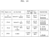
- FIG. 10 is a diagram for describing a type of the brush device 2000, according to an embodiment of the disclosure.
- the brush device 2000 may be classified into four types according to an internal circuit design.
- the brush device 2000 may be classified into the first type of brush device 2001 including the ID resistor 2500, the second type of brush device 2002 in which the signal line 30 is short-circuited to the positive (+) power line 10, the third type of brush device 2003 in which the signal line 30 is short-circuited to the negative (-) power line 20, and the fourth type of brush device 2004 in which the signal line 30 is open.
- the cleaner body 1000 may identify a type of the brush device 2000, by considering a signal ⁇ (high or low) output to the PWM control switch device 1133, based on an input voltage value AD #2 battery V ⁇ C B + C when the second type of brush device 2002 is connected.
- the input voltage value AD #2 when the second type of brush device 2002 is connected may be defined as a maximum input voltage value.
- the cleaner body 1000 may identify that the brush device 2000 connected to the cleaner body 1000 is the second type of brush device 2002 in which the signal line 30 is short-circuited to the (+) power line 10; 2) when an input voltage value when the signal ⁇ output to the PWM control switch device 1133 is a low signal is the maximum input voltage value AD #2 and an input voltage value when the signal ⁇ output to the PWM control switch device 1133 is a high signal is 0 (GND), the cleaner body 1000 may identify that the brush device 2000 connected to the cleaner body 1000 is the third type of brush device 2003 in which the signal line 30 is short-circuited to the (-) power line 20; 3) when an input voltage value is 0 (GND) regardless of the signal ⁇ (high or low) output to the PWM control switch device 1133, the cleaner body 1000 may identify that the brush device 2000 attached to the cleaner body 1000 is the fourth type
- FIG. 11A is a diagram for describing a method in which the cordless vacuum cleaner 100 controls an operation of the switch device 1133 for controlling power supply to the brush device 2000, according to an embodiment of the disclosure.
- the cordless vacuum cleaner 100 may detect connection of the brush device 2000 to the cleaner body 1000.
- the cordless vacuum cleaner 100 may detect connection of the brush device 2000 to the cleaner body 1000 based on a voltage value input to an input port of at least one processor 1001 through the signal line 30 or the load detection sensor 1134.
- the brush device 2000 may be directly connected to the cleaner body 1000 or may be indirectly connected to the cleaner body 1000 through the extension pipe 3000.
- the at least one processor 1001 of the cordless vacuum cleaner 100 may detect whether the brush device 2000 is attached or detached by using the load detection sensor 1134. For example, when the brush device 2000 is not connected to the cordless vacuum cleaner 100 (e.g., a handy mode), operating current of the brush device 2000, detected by the load detection sensor 1134, may be 0 (zero). On the other hand, when the brush device 2000 is connected to the cordless vacuum cleaner 100 (e.g., a brush mode), the operating current of the brush device 2000, detected by the load detection sensor 1134, may be equal to or greater than 50 mA.
- the first processor 1131 may determine that the brush device 2000 is detached when the operating current of the brush device 2000, detected by the load detection sensor 1134, is 0, and that the brush device 2000 is connected when the operating current of the brush device 2000, detected by the load detection sensor 1134, is 50 mA or more.
- a value of a reference operating current for determining that the brush device 2000 is connected is not limited to 50 mA, and may be changed.
- the at least one processor 1001 of the cordless vacuum cleaner 100 may detect connection of the brush device 2000 to the cleaner body 1000 through a voltage value (hereinafter, referred to as an input voltage value) input to an input port of the at least one processor 1001 through the signal line 30.
- an input voltage value may be "0 V”.
- the input voltage value may be greater than 0 V, and may vary according to a type of the brush device 2000. For example, referring to FIG.
- the input voltage value when a voltage of the battery 1500 is 25.2 V, the input voltage value may be 2.785 V when the multi-brush 401 is connected to the cleaner body 1000, and the input voltage value may be 0.791 V when the hard floor brush 402 is connected to the cleaner body 1000. Accordingly, when the input voltage value is 0 V, the at least one processor 1001 of the cordless vacuum cleaner 100 may determine that the brush device 2000 is detached, and when the input voltage value is greater than 0 V, the at least one processor 1001 may determine that the brush device 2000 is connected.
- the cordless vacuum cleaner 100 may identify a type of the brush device 2000 connected to the cleaner body 1000.
- the type of the brush device 2000 may be identified, based on a voltage value (hereinafter, referred to as an input voltage value) input to the input port of the at least one processor 1001 of the cordless vacuum cleaner 100.
- a voltage value hereinafter, referred to as an input voltage value
- the at least one processor 1001 may identify the brush device 2000 including an ID resistor corresponding to the input voltage value.
- the ID resistor may be located between the + power line 10 and the signal line 30 in the brush device 2000.
- the maximum input voltage value may be a voltage value input to the input port when the ID resistor is 0 (i.e., when the signal line is short-circuited to the (+) power line).
- the brush device 2000 connected to the cleaner body 1000 may be the first type of brush device 2001 having an ID resistor greater than 0.
- the at least one process 1001 of the cordless vacuum cleaner 100 may directly identify the first type of brush device 2001 including the ID resistor corresponding to the input voltage value in a prestored table to identify a type of the brush device 2000.
- the at least one processor 1001 may identify a type of the brush device 2000, based on a change in the input voltage value according to an operation (ON/OFF) state of the switch device 1133. For example, when the voltage value (input voltage value) input through the signal line 30 is the maximum input voltage value or the minimum input voltage value, the at least one processor 1001 may determine that the brush device 2000 connected to the cleaner body 1000 is not the first type of brush device 2001 including the ID resistor 2500.
- the at least one processor 1001 may change the PWM control switch device 1133 to an on state and then to an off state again. Also, the at least one processor 1001 may identify a specific type of the brush device 2000 connected to the cleaner body 1000, by comparing the input voltage value when the PWM control switch device 1133 is in an on state with the input voltage value when the switch device 1133 is in an off state.
- the at least one processor 1001 may identify that the second type of brush device 2002 in which the signal line 30 is short-circuited to the (+) power line 10 is the brush device 2000 connected to the cleaner body 1000.
- the wet brush 403 may be implemented so that the signal line is short-circuited to the (+) power line.
- the at least one processor 1001 may identify that the brush device 2000 connected to the cleaner body 1000 is the wet brush 403.
- the at least one processor 1001 may identify that the third type of brush device 2003 in which the signal line 30 is short-circuited to the (-) power line 10 is the brush device 2000 connected to the cleaner body 1000.
- the bedding brush 405 may be implemented so that the signal line 30 is short-circuited to the (-) power line 10.
- the at least one processor 1001 may identify that the brush device 2000 connected to the cleaner body 1000 is the bedding brush 405.
- the at least one processor 1001 may identify that the fourth type of brush device 2004 in which the signal line 30 is open is the brush device 2000 connected to the cleaner body 1000.
- the pet brush 406 may be implemented so that the signal line 30 is open.
- the at least one processor 1001 may identify that the brush device 2000 connected to the cleaner body 1000 is the pet brush 406.
- the cordless vacuum cleaner 100 may determine a frequency (hereinafter, referred to as a PWM frequency) for PWM control corresponding to the type of the brush device 2000.
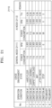
- the cordless vacuum cleaner 100 may select (search for) a PWM frequency corresponding to the type of the brush device 2000 in a PWM frequency table.
- a pre-determined PWM frequency for each type of the brush device 2000 may be defined in the PWM frequency table.
- an optimal frequency considering noise, electrical noise, and a counter electromotive force by the motor 2100 for each type of the brush device 2000 may be defined in the PWM frequency table.
- the cordless vacuum cleaner 100 may select a different frequency for PWM control according to a type of the brush device 2000, thereby increasing the motor efficiency of the brush device 2000 and reducing (avoiding resonance) abnormal noise and abnormal vibration.
- a PWM frequency of the jet brush may be adjusted to 1 kHz or 3 kHz instead of 2 kHz, by considering abnormal noise.
- a PWM frequency may be determined by considering driving current of the brush device 2000.
- driving current (or voltage) of the brush device 2000 may vary according to a type (e.g., A type, B type, C type, or D type of the motor 2100) of the brush device 2000.
- a PWM frequency may be determined to increase as driving current corresponding to the type of the brush device 2000 connected to the cleaner body 1000 increases, and decrease as driving current corresponding to the type of the brush device 2000 connected to the cleaner body 1000 decreases.
- a PWM frequency may be determined to increase as a maximum motor output value corresponding to the type of the brush device 2000 connected to the cleaner body 1000 increases, and decrease as a maximum motor output value corresponding to the type of the brush device 2000 connected to the cleaner body 1000 decreases.
- the cordless vacuum cleaner 100 may determine a PWM frequency of a light load brush (e.g., a bedding brush) having a relatively low maximum motor output value to be lower than a PWM frequency of a general load brush (e.g., a hard floor brush), thereby reducing switching loss of the PWM control switch device 1133.
- the cordless vacuum cleaner 100 may determine a PWM frequency of a high load brush (e.g., a carpet brush) having a relatively high maximum motor output value to be higher than a PWM frequency of a general load brush (e.g., a hard floor brush), thereby improving the efficiency of the motor 2100 of the brush device 2000.
- a high load brush e.g., a carpet brush
- a general load brush e.g., a hard floor brush
- the cordless vacuum cleaner 100 may determine a frequency range for PWM control corresponding to the type of the brush device 2000.
- a frequency determined for PWM control may vary between 0.5 kHW and 8 kHz according to the type of the brush device 2000.
- the PWM control switch device 1133 may be determined to operate in a frequency range of 0.5 kHz to 2 kHz, and when it is identified that the carpet brush 404 is connected on the cleaner body 1000, the PWM control switch device 1133 may be determined to operate in a frequency range of 1.0 kHz to 3.0 kHz which is higher than the frequency range of the hard floor brush 402.
- the cordless vacuum cleaner 100 may select a specific PWM frequency, by considering an actual load value of the brush device 2000 and a suction power strength of the cleaner body 1000 in a frequency range corresponding to the type of the brush device 2000.
- the cordless vacuum cleaner 100 may control an operation of the switch device 1133 for controlling power supply to the brush device 2000, based on the frequency corresponding to the type of the brush device 2000.
- the at least one processor 1001 of the cordless vacuum cleaner 100 may alternately output a high signal and a low signal to the PWM control switch device 1133, according to the PWM frequency corresponding to the type of the brush device 2000.
- the PWM control switch device 1133 may be turned on when the high signal is input and may be turned off when the low signal is input. Accordingly, an on state and an off state of the PWM control switch device 1133 may be repeated according to the PWM frequency.
- optimal control suitable for characteristics of the brush device 2000 may be performed, by adjusting the PWM frequency according to the type of the brush device 2000 connected to the cordless vacuum cleaner 100.
- operations S1110 to S1140 may be performed by the at least one processor 1001 of the cordless vacuum cleaner 100.
- operations S1110 to S1140 may be performed by the main processor 1800, or may be performed by the first processor 1131 of the suction motor 1110.
- some of operations S1110 to S1140 may be performed by the main processor 1800, and others may be performed by the first processor 1131 of the suction motor 1110.
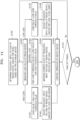
- FIG. 12 is a flowchart for describing a method of determining parameters related to driving of the brush device 2000, based on a type of the brush device 2000, according to an embodiment of the disclosure.
- the cordless vacuum cleaner 100 may initialize a system, as a user input that turns on the power is received. For example, according to a user input that turns on the power, the cordless vacuum cleaner 100 may wake up the battery 1500 and may supply power to a circuit such as at least one processor 1001.
- the cordless vacuum cleaner 100 may determine whether the brush device 2000 is connected to the cleaner body 1000.
- the brush device 2000 may be directly connected to the cleaner body 1000 or may be connected to the cleaner body 1000 through the extension pipe 3000.
- the cordless vacuum cleaner 100 may detect whether the brush device 2000 is attached or detached by using the load detection sensor 1134. For example, when operating current of the brush device 2000 detected by the load detection sensor 1134 is 0, the at least one processor 1001 of the cordless vacuum cleaner 100 may determine that the brush device 2000 is detached, and when operating current of the brush device 2000 detected by the load detection sensor 1134 is 50 mA or more, the at least one processor 1001 may determine that the brush device 2000 is connected.
- the cordless vacuum cleaner 100 may operate in a handy mode 1201 (e.g., handheld mode), and the method returns to operation S1220.
- the handy mode 1201 may be a mode in which the brush device 2000 is detached and cleaning is performed by using only the cleaner body 1000.
- the cordless vacuum cleaner 100 may operate in a brush mode 1202.
- the brush mode 1202 may be a mode in which the brush device 2000 is connected to the cordless vacuum cleaner 100 and cleaning is performed.
- the handy mode 1201 may operate with a higher suction power strength than the brush mode 1202.
- a jet mode may be set in the cordless vacuum cleaner 100.
- the cordless vacuum cleaner 100 may drive the suction motor 1110 with power consumption of 580 W to generate suction power of 220 W, but in the brush mode 1202, the cordless vacuum cleaner 100 may drive the suction motor 1110 with power consumption of 335 W to generate suction power of 140 W.
- the cordless vacuum cleaner 100 identifies a type of the brush device 2000 connected to the cleaner body 1000.
- a type of the brush device 2000 can be identified, based on a voltage value (hereinafter, an input voltage value) input to an input port of the at least one processor 1001 of the cordless vacuum cleaner 100.
- Operation S1250 corresponds to operation S1120 of FIG. 11A , and thus, a detailed description thereof will be omitted.
- the cordless vacuum cleaner 100 may determine at least one of a frequency for PWM control (PWM frequency), an input voltage of the brush device 2000, and/or a trip level, based on the type of the brush device 2000.
- PWM frequency a frequency for PWM control
- an input voltage of the brush device 2000 a voltage of the brush device 2000
- a trip level a trip level
- the cordless vacuum cleaner 100 may determine a PWM frequency, based on the type of the brush device 2000.
- the cordless vacuum cleaner 100 may determine an input voltage of the brush device 2000 and a PWM frequency, based on the type of the brush device 2000.
- the cordless vacuum cleaner 100 may determine a PWM frequency, an input voltage of the brush device 2000, and a trip level, based on the type of the brush device 2000.
- an operation in which the cordless vacuum cleaner 100 determines a PWM frequency based on the type of the brush device 2000 is the same as operation S1130 of FIG. 11A , and thus, a repeated description thereof will be omitted.
- the cordless vacuum cleaner 100 may determine an input voltage of the brush device 2000 in addition to a PWM frequency, based on the type of the brush device 2000.
- the input voltage of the brush device 2000 that is a voltage required by the brush device 2000 to drive the drum 2200 at target RPM may vary according to the type of the brush device 2000.
- the brush device 2000 requires a different electrical input according to characteristics of each type (usage). For example, a first motor applied to the hard floor brush 402 having a large width may require a moderate output to rotate the drum 2200 at target RPM, and a second motor applied to the pet brush 406 having a small width may drive the drum 2200 at target RPM with a relatively low output. Accordingly, the cordless vacuum cleaner 100 may determine an input voltage of the brush device 2000 when the brush device 2000 connected to the cleaner body 1000 is the pet brush 406 to be lower than that when the brush device 2000 connected to the cleaner body 1000 is the hard floor brush 402.
- an input voltage of the brush device 2000 may refer to an average voltage to be supplied to the brush device 2000 through PWM control. Accordingly, as an input voltage of the brush device 2000 increases, the cordless vacuum cleaner 100 may increase a duty value (on-duty interval) of the PWM control switch device 1133 to supply a more voltage from the battery 1500 to the brush device 2000. Because a total time for which current flows through the motor 2100 increases as a duty value increases, average power supplied to the brush device 2000 may increase.
- the cordless vacuum cleaner 100 may reduce a duty value (on-duty interval) of the PWM control switch device 1133 to supply a less voltage from the battery 1500 to the brush device 2000. Because a total time for which current flows through the motor 2100 decreases as a duty value decreases, average power supplied to the brush device 2000 may be reduced. When average power supplied to the brush device 2000 decreases, a usage time of the battery 1500 may be efficiently increased.
- the cordless vacuum cleaner 100 may determine a trip level of the brush device 2000 in addition to a PWM frequency, based on the type of the brush device 2000.
- a trip level for preventing an overload of the brush device 2000 may refer to a reference load value (e.g., a reference current value) for stopping an operation of the brush device 2000.
- the cordless vacuum cleaner 100 may control the PWM control switch device 1133 to cut off power supply to the brush device 2000.
- the cordless vacuum cleaner 100 may select (search for) a trip level corresponding to the type of the brush 2000 in a trip level table.
- a pre-determined trip level for each type of the brush device 2000 may be defined in the trip level table.
- a trip level may be determined to increase as a maximum motor output value corresponding to the type of the brush device 2000 connected to the cleaner body 1000 increases, and may be determined to decrease as a maximum motor output value corresponding to the type of the brush device connected to the cleaner body 1000 decreases.
- the cordless vacuum cleaner 100 may determine a trip level of a light load brush (e.g., a bedding brush) having a relatively low maximum motor output value to be lower than that of a general load brush (e.g., a hard floor brush), thereby preventing a failure of the light load brush due to an overload.
- a trip level of the general load brush is 2.0 A
- the cordless vacuum cleaner 100 may determine a trip level of the light load brush to be 1.5A, thereby improving the durability of the brush device 2000.
- the cordless vacuum cleaner 100 may determine a trip level of a high load brush (e.g., a carpet brush) having a relatively high maximum motor output value to be higher than that of a general load brush (e.g., a hard floor brush), to prevent the brush device 2000 from frequently stopping in a high load situation in which the brush device 2000 may withstand.
- a trip level of the general load brush is 2.0 A
- the cordless vacuum cleaner 100 may determine a trip level of the high load brush to be 2.2 A, thereby improving the usability of the brush device 2000.
- the cordless vacuum cleaner 100 may control a PWM frequency, an average voltage supplied to the brush device 2000 or a trip level of the brush device 2000 according to the type of the brush device 2000, thereby providing optimal control suitable for characteristics of the brush device 2000 connected to the cleaner body 1000. Accordingly, according to an embodiment of the disclosure, the cleaning efficiency of the brush device 2000 may be improved, abnormal noise and abnormal vibration may be reduced (resonance is avoided), electrical noise may be reduced, and a usage time of the cordless vacuum cleaner 100 may be increased, which will be further described with reference to FIG. 13 .
- FIG. 13 is a view for describing an operation of determining parameters related to driving of the brush device 2000, based on a type of the brush device 2000, according to an embodiment of the disclosure.
- various types of brush devices 2000 may be connected on the cordless vacuum cleaner 100 according to cleaning purposes.
- a hard floor brush 1301, a wet brush 1302, and a pet brush 1303 may be connected on the cordless vacuum cleaner 100.
- the cordless vacuum cleaner 100 may identify a type of the brush device 2000 connected by a user according to a cleaning purpose, and may provide control suitable for the type of the brush device 2000.
- the cordless vacuum cleaner 100 may determine a PWM frequency to be 0.5 kHz, may determine an input voltage of the brush device 2000 to be 16 V, and may determine a trip level to be 1.5 A. In this case, the cordless vacuum cleaner 100 may control the PWM control switch device 1133 to supply power to the hard floor brush 1301 with a duty value corresponding to 16 V at a frequency of 0.5 kHz.
- the cordless vacuum cleaner 100 may control the PWM control switch device 1133 to cut off power supply to the hard floor brush 1301.
- the first processor 1131 of the cleaner body 1000 may output a low signal to the PWM control switch device 1133 to change an operation state of the PWM control switch device 1133 to an off state.
- the cordless vacuum cleaner 100 may determine a PWM frequency to be 1.0 kHz, may determine an input voltage of the brush device 2000 to be 18 V, and may determine a trip level to be 2.0 A. In this case, the cordless vacuum cleaner 100 may control the PWM control switch device 1133 to supply power to the wet brush 1302 with a duty value corresponding to 18 V at a frequency of 1.0 kHz.
- the cordless vacuum cleaner 100 may control the PWM control switch device 1133 to cut off power supply to the wet brush 1302.
- the first processor 1131 of the cleaner body 1000 may output a low signal to the PWM control switch device 1133 to change an operation state of the PWM control switch device 1133 to an off state.
- the cordless vacuum cleaner 100 may determine a PWM frequency to be 1.0 kHz, may determine an input voltage of the brush device 2000 to be 16 V, and may determine a trip level to be 1.0 A. In this case, the cordless vacuum cleaner 100 may control the PWM control switch device 1133 to supply power to the pet brush 1303 with a duty value corresponding to 16 V at a frequency of 0.5 kHz.
- the cordless vacuum cleaner 100 may control the PWM control switch device 1133 to cut off power supply to the pet brush 1303.
- the first processor 1131 of the cleaner body 1000 may output a low signal to the PWM control switch device 1133 to change an operation state of the PWM control switch device 1133 to an off state.
- the cordless vacuum cleaner 100 may adaptively adjust a PWM frequency, an input voltage of the brush device 2000, and a trip level corresponding to the type of the brush device 2000, based on an actual load value of the brush device 2000 measured during cleaning. An operation in which the cordless vacuum cleaner 100 adjusts parameters related to driving of the brush device 2000 based on an actual load value of the brush device 2000 will be described with reference to FIG. 14 .
- FIG. 14 is a flowchart for describing a method of adjusting parameters related to driving of the brush device 2000 based on a load value of the brush device 2000, according to an embodiment of the disclosure.
- the cordless vacuum cleaner 100 may determine at least one of a frequency for PWM control (PWM frequency), an input voltage of the brush device 2000, or a trip level, based on a type of the brush device 2000.
- Operation S1401 corresponds to operation S1250 of FIG. 12 , and thus, a detailed description thereof will be omitted.
- the cordless vacuum cleaner 100 may measure a load value of the brush device 2000.
- the cordless vacuum cleaner 100 may monitor an actual load value of the brush device 2000 through the load detection sensor 1134 while supplying power to the brush device 2000 according to the PWM frequency, the input voltage of the brush device 2000, or the trip level determined based on the type of the brush device 2000.
- the cordless vacuum cleaner 100 may identify that the load value of the brush device 2000 measured through the load detection sensor 1134 is greater than a high load reference value.
- the high load reference value may be a reference load value for determining a state of the brush device 2000 as a high load state.
- the high load reference value may be different from the trip level for determining an overload.
- the high load reference value may be lower than the trip level.
- the high load reference value may vary according to the type of the brush device 2000. For example, referring to FIG. 15 , the high load reference value of a hard floor brush 1501 may be 1.2 A, the high load reference value of a wet brush 1502 may be 1.5 A, and the high load reference value of a bedding brush 1503 may be 0.8 A, but an embodiment of the disclosure is not limited thereto.
- the high load reference value may vary according to a suction power mode set in the cordless vacuum cleaner 100 or a suction power strength (or power consumption) of the cleaner body 1000.
- the cordless vacuum cleaner 100 may adjust the PWM frequency, the input voltage of the brush device 2000, and/or the trip level determined for PWM control to be higher.
- the cordless vacuum cleaner 100 may determine that the brush device 2000 is in a high load state. Accordingly, the cordless vacuum cleaner 100 may adjust the frequency, the input voltage of the brush device 2000, and/or the trip level determined for PWM control to be higher, by reflecting the high load state of the brush device 2000. For example, when foreign materials are caught by the brush device 2000 or a usage environment state of the brush device 2000 changes from a hard floor to a carpet, the load value of the brush device 2000 may be greater than the high load reference value.
- the cordless vacuum cleaner 100 may increase the PWM frequency, thereby improving the efficiency of the motor 2100 of the brush device 2000. Also, when the brush device 2000 is in the high load state, because a larger voltage is required by the brush device 2000, the cordless vacuum cleaner 100 may increase the input voltage of the brush device 2000 and may control the PWM control switch device 1133 to supply power to the brush device 2000 with a duty value corresponding to the increased duty value. When the brush device 2000 is in the high load state, the cordless vacuum cleaner 100 may adjust the trip level to be higher, to prevent the brush device 2000 from frequently stopping in the high load state.
- the cordless vacuum cleaner 100 may rather reduce the PWM control frequency, the input voltage of the brush device 2000, and the trip level.
- the abnormal high load reference value may be a load value that may cause a problem when the brush device 2000 is driven for a certain period of time in the current load state. This is because, when a load equal to or greater than the abnormal high load reference value is applied to the brush device 2000, the risk of failure (decrease in quality and reliability) increases due to increased circuit device loss and an overload of the motor 2100 of the brush device 2000.
- the cordless vacuum cleaner 100 may identify that the load value of the brush device 2000 measured through the load detection sensor 1134 is between the high load reference value and a low load reference value (in a general load state).
- the low load reference value may be a reference load value for determining a state of the brush device 2000 as a low load state.
- the low load reference value may vary according to the type of the brush device 2000, a suction power mode set in the cordless vacuum cleaner 100, and/or a suction power strength (or power consumption) of the cleaner body 1000.
- the cordless vacuum cleaner 100 may maintain a current state of the frequency, the input voltage of the brush device 2000, and/or the trip level determined for PWM control.
- an operation state of the brush device 2000 may be considered stable, and thus, the cordless vacuum cleaner 100 may maintain current settings of parameters related to driving of the brush device 2000.
- the cordless vacuum cleaner 100 may identify that the load value of the brush device 2000 measured through the load detection sensor 1134 is less than the low load reference value.
- the cordless vacuum cleaner 100 may adjust the frequency, the input voltage of the brush device 2000, and/or the trip level determined for PWM control to be lower.
- the cordless vacuum cleaner 100 may determine that the brush device 2000 is in a low load state. Accordingly, the cordless vacuum cleaner 100 may adjust the frequency, the input voltage of the brush device 2000, and/or the trip level determined for PWM control to be lower, by reflecting the low load state of the brush device 2000. For example, when the brush device 2000 is lifted from a surface to be cleaned or a usage environment state of the brush device 2000 changes from a carpet to a hard floor, the load value of the brush device 2000 may be less than the low load reference value.
- the cordless vacuum cleaner 100 may reduce the PWM frequency, to reduce switching loss and electrical noise of the PWM control switch device 1133.
- the cordless vacuum cleaner 100 may reduce the input voltage of the brush device 2000 and may control the PWM control switch device 1133 to supply power to the brush device 2000 with a duty value corresponding to the reduced input voltage.
- drum RPM of the brush device 2000 may be reduced, noise unnecessarily generated in the brush device 2000 may be reduced and a usage time of the battery 1500 may be increased.
- the cordless vacuum cleaner 100 may adjust the trip level to be lower, to improve the durability of the brush device 2000.
- the cordless vacuum cleaner 100 may control an operation of the PWM control switch device 1133, according to the PWM frequency, the input voltage of the brush device 2000, and/or the trip level adjusted by reflecting the load value of the brush device 2000.
- the cordless vacuum cleaner 100 may control the PWM control switch device 1133 to supply power to the brush device 2000 with a duty value corresponding to the adjusted input voltage of the brush device 2000 at the adjusted PWM frequency. Also, when the load value of the brush device 2000 reaches a load value of the adjusted trip level, the cordless vacuum cleaner 100 may control the PWM control switch device 1133 to cut off power supply to the brush device 2000.
- the cordless vacuum cleaner 100 may repeatedly perform operations S1402 to S1409 until a user input that turns off the power is received.
- the cordless vacuum cleaner 100 may adaptively control power supply to the brush device 2000 according to a real-time load value of the brush device 2000 by monitoring the load value of the brush device 2000 during cleaning through the load detection sensor 1134.
- the cordless vacuum cleaner 100 may divide a state of the brush device 2000 into two or less states (e.g., high load state/general load state, high load state/low load state, or general load state/low load state) to more simply control the PWM frequency, the input voltage of the brush device 2000, and the trip level.
- states e.g., high load state/general load state, high load state/low load state, or general load state/low load state
- the cordless vacuum cleaner 100 may divide a state of the brush device 2000 into four or more states (e.g., ultra-high load state/high load state/general load state/low load state, or ultra-high load state/high load state/general load state/low load state/ultra-low load state) to more finely control the PWM frequency, the input voltage of the brush device 2000, and the trip level.
- states e.g., ultra-high load state/high load state/general load state/low load state, or ultra-high load state/high load state/general load state/low load state/ultra-low load state
- FIG. 15 is a view for describing an operation in which the brush device 2000 adjusts parameters related to driving of the brush device 2000 when the brush device 2000 is in a high load state, according to an embodiment of the disclosure.
- the cordless vacuum cleaner 100 may identify a type of the brush device 2000 connected by a user according to a cleaning purpose, and may provide control suitable for the type of connected brush device 2000. In this case, when the brush device 2000 is in a high load state, based on an actual load value of the brush device 2000, the cordless vacuum cleaner 100 may adjust parameters related to driving of the brush device 2000 to be higher than current settings.
- the cordless vacuum cleaner 100 may determine an initial PWM frequency to be 0.5 kHz, an initial input voltage of the hard floor brush 1501 to be 16 V, and may determine an initial trip level to be 1.5 A. In this case, the cordless vacuum cleaner 100 may control the PWM control switch device 1133 to supply power to the hard floor brush 1501 with a duty value corresponding to 16 V at a frequency of 0.5 kHz.
- the cordless vacuum cleaner 100 may determine that the hard floor brush 1501 is in a high load state. Accordingly, the cordless vacuum cleaner 100 may change the PWM frequency from 0.5 kHz to 1.0 kHz, may change the input voltage of the hard floor brush 1501 from 16 V to 18 V, and may change the trip level from 1.5 A to 2.0 A. In this case, the cordless vacuum cleaner 100 may control the PWM control switch device 1133 to supply power to the hard floor brush 1501 with a duty value corresponding to 18 V at a frequency of 1.0 kHz.
- the cordless vacuum cleaner 100 may control the PWM control switch device 1133 not to cut off power supply to the hard floor brush 1501 when the load value of the hard floor brush 1501 reaches 1.5 A, but may control the PWM control switch device 1133 to cut off power supply to the hard floor brush 1502 when the load value of the hard floor brush 1501 reaches 2.0 A.
- the cordless vacuum cleaner 100 may determine an initial PWM frequency to be 1.0 kHz, may determine an initial input voltage of the wet brush 1502 to be 18 V, and may determine an initial trip level to be 2.0 A.
- the cordless vacuum cleaner 100 may control the PWM control switch device 1133 to supply power to the wet brush 1502 with a duty value corresponding to 18 V at a frequency of 1.0 kHz.
- the cordless vacuum cleaner 100 may determine that the wet brush 1502 is in a high load state. Accordingly, the cordless vacuum cleaner 100 may change the PWM frequency from 1.0 kHz to 2.5 kHz, may change the input voltage of the wet brush 1502 from 18 V to 20 V, and may change the trip level from 2.0 A to 3.0 A. In this case, the cordless vacuum cleaner 100 may control the PWM control switch device 1133 to supply power to the wet brush 1502 with a duty value corresponding to 20 V at a frequency of 2.5 kHz.
- the cordless vacuum cleaner 100 may control the PWM control switch device 1133 not to cut off power supply to the wet brush 1502 when the load value of the wet brush 1502 reaches 2.0 A, but may control the PWM control switch device 1133 to cut off power supply to the wet brush 1502 when the load value of the wet brush 1502 reaches 3.0 A.
- the cordless vacuum cleaner 100 may determine an initial PWM frequency to be 1.0 kHz, may determine an initial input voltage of the pet brush 1503 to be 16 V, and may determine an initial trip level to be 1.0 A. In this case, the cordless vacuum cleaner 100 may control the PWM control switch device 1133 to supply power to the pet brush 1503 with a duty value corresponding to 16 V at a frequency of 1.0 kHz.
- the cordless vacuum cleaner 100 may determine that the pet brush 1503 is in a high load state. Accordingly, the cordless vacuum cleaner 100 may change the PWM frequency from 1.0 kHz to 2.0 kHz, may change the input voltage of the pet brush 1503 from 16 V to 18 V, and may change the trip level from 1.0 A to 1.5 A. In this case, the cordless vacuum cleaner 100 may control the PWM control switch device 1133 to supply power to the pet brush 1503 with a duty value corresponding to 18 V at a frequency of 2.0 kHz.
- the cordless vacuum cleaner 100 may control the PWM control switch device 1133 not to cut off power supply to the pet brush 1503 when the load value of the pet brush 1503 reaches 1.0 A, but may control the PWM control switch device 1133 to cut off power supply to the pet brush 1503 when the load value of the pet brush 1503 reaches 1.5 A.
- the cordless vacuum cleaner 100 may adjust parameters related to driving of the brush device 2000 according to the suction power strength of the cleaner body 1000. For example, when the same brush device 2000 is connected but the suction power strength of the cleaner body 1000 increases, the cordless vacuum cleaner 100 may increase at least one of a PWM frequency, an input voltage of the brush device 2000, or a trip level. In contrast, when the same brush device 2000 is connected but the suction power strength of the cleaner body 1000 decreases, cordless vacuum cleaner 100 may reduce at least one of the PWM frequency, the input voltage of the brush device 2000, or the trip level.
- An operation in which the cordless vacuum cleaner 100 adjusts parameters related to driving of the brush device 2000 based on a suction power strength will be described in detail with reference to FIG. 16 .
- FIG. 16 is a flowchart for describing a method in which the cordless vacuum cleaner 100 adjusts parameters related to driving of the brush device 2000 based on a suction power strength, according to an embodiment of the disclosure.
- the cordless vacuum cleaner 100 may detect connection of the brush device 2000 to the cleaner body 1000, through a voltage value input to an input port of at least one processor 1001 through the signal line 30 or the load detection sensor 1134.
- the cordless vacuum cleaner 100 may detect whether the brush device 2000 is connected or disconnected (e.g., attached or detached by using the load detection sensor 1134.
- the at least one processor 1001 of the cordless vacuum cleaner 100 may determine that the brush device 2000 is disconnected, and when operating current of the brush device 2000 detected by the load detection sensor 1134 is 50 mA or more, the at least one processor 1001 of the cordless vacuum cleaner 100 may determine that the brush device 2000 is connected.
- the at least one processor 1001 of the cordless vacuum cleaner 100 may detect connection of the brush device 2000 to the cleaner body 1000 through a voltage value (hereinafter, an input voltage value) input to the input port of the at least one processor 1001 through the signal line 30. For example, when the input voltage value is 0 V, the at least one processor 1001 of the cordless vacuum cleaner 100 may determine that the brush device 2000 is disconnected, and when the input voltage value is greater than 0 V, the at least one processor 1001 may determine that the brush device 2000 is connected.
- a voltage value hereinafter, an input voltage value
- the cordless vacuum cleaner 100 may identify a type of the brush device 2000 connected to the cleaner body 1000.
- the type of the brush device 2000 may be identified based on a voltage value (hereinafter, referred to as an input voltage value) input to the input port of the at least one processor 1001 of the cordless vacuum cleaner 100 through the signal line.
- Operation S1620 corresponds to operation S1120 of FIG. 11A , and thus, a detailed description thereof will be omitted.
- the cordless vacuum cleaner 100 may determine at least one of a frequency, an input voltage of the brush device 2000, and/or a trip level based on the type of the brush device 2000. For example, the cordless vacuum cleaner 100 may determine a PWM frequency, based on the type of the brush device 2000. The cordless vacuum cleaner 100 may determine the PWM frequency and the input voltage of the brush device 2000, based on the type of connected brush device 2000. The cordless vacuum cleaner 100 may determine the PWM frequency, the input voltage of the brush device 2000, and/or the trip level, based on the type of connected brush device 2000.
- Operation S1630 corresponds to operation S1260 of FIG. 12 , a detailed description thereof will be omitted.
- the cordless vacuum cleaner 100 may adjust at least one of the frequency, the input voltage of the brush device 2000, and/or the trip level determined for PWM control, based on a suction power strength of the cleaner body 1000.
- the cordless vacuum cleaner 100 may adjust the PWM frequency, the input voltage of the brush device 2000, and/or the trip level to be higher as the suction power strength of the cleaner body 1000 increases.
- the suction power strength of the cleaner body 1000 increases, it means that greater cleaning performance is required by the cordless vacuum cleaner 100, and thus, the cordless vacuum cleaner 100 may adjust the PWM frequency and the input voltage of the brush device 2000 to be higher.
- the cordless vacuum cleaner 100 may adjust the trip level to be higher, to prevent the brush device 2000 from frequently stopping.
- the cordless vacuum cleaner 100 may adjust the PWM frequency, the input voltage of the brush device 2000, and/or the trip level to be lower as the suction power strength of the cleaner body 1000 decreases.
- the cordless vacuum cleaner 100 may adjust the PWM frequency and the input voltage of the brush device 2000 to be lower, to reduce switching loss of the PWM control switch device 1133 and increase a usage time of the battery 1500.
- the cordless vacuum cleaner 100 may adjust the trip level to be lower, to improve the durability of the brush device 2000.
- the suction power strength of the cleaner body 1000 may vary according to a suction power mode selected by a user, or may be automatically changed by using an artificial intelligence (Al) model.
- Al artificial intelligence
- An operation in which the suction power strength of the cleaner body 1000 is automatically changed by using the AI model will be described below in detail with reference to FIG. 18 .
- the cordless vacuum cleaner 100 may receive a user input that selects one of a plurality of suction power modes respectively having different suction power strengths.
- the cordless vacuum cleaner 100 may receive a user input that selects one of a general suction power mode, a strong mode, a super strong mode, and a jet mode.
- the suction power strength may increase from the general suction power mode to the jet mode. That is, the strong mode has greater suction power than the general suction power mode, the super strong mode has a greater suction power than the general suction power mode and the strong mode, and the jet mode has a greater suction power than the general suction power mode, the strong mode, and the super strong mode.
- a plurality of suction power modes include four modes in the disclosure, an embodiment of the disclosure is not limited thereto.
- the plurality of suction power modes may include 5 or more modes, or three or less modes.
- the cordless vacuum cleaner 100 may adjust at least one of the frequency, the input voltage of the brush device 2000, and the trip level determined for PWM control, based on the suction power strength of the suction power mode selected by the user input, which will be further described with reference to FIG. 17 .
- FIG. 17 is a view for describing an operation of adjusting parameters related to driving of the brush device 2000 based on a suction power mode selected by a user, according to an embodiment of the disclosure.
- the user may select a suction power mode among a plurality of different suction power modes according to a cleaning environment or a preference.
- the plurality of different suction power modes include, but are not limited to, a suction power mode 1701, a strong mode 1702, a super strong mode 1703, and a jet mode 1704.
- a suction power strength of the cleaner body 1000 may increase from the general suction power mode 1701 to the jet mode 1704.
- suction power of the general suction power mode 1701 may be 18 W
- suction power of the strong mode 1702 may be 40 W
- suction power of the super strong mode 1703 may be 90 W
- suction power of the jet mode 1704 may be 140 W.
- the cordless vacuum cleaner 100 may determine a PWM frequency to be 0.5 kHz, may determine an input voltage of the hard floor brush 1711 to be 16 V, and may determine a trip level to be 1.5 A. Accordingly, when the user selects the general suction power mode 1701, the cordless vacuum cleaner 100 may control the PWM control switch device 1133 to supply power to the hard floor brush 1711 with a duty value corresponding to 16 V at a frequency of 0.5 kHz.
- the cordless vacuum cleaner 100 may further improve cleaning performance according to the user's intention by adjusting the PWM frequency from 0.5 kHz to 2.0 kHz, the input voltage of the hard floor brush 1711 from 16 V to 18 V, and the trip level from 1.5 A to 2.5 A.
- the cordless vacuum cleaner 100 may adjust the PWM frequency from 2.0 kHz to 0.5 kHz, the input voltage of the hard floor brush 1711 from 18 V to 16 V, and the trip level from 2.5 A to 1.5 A, thereby preventing unnecessary waste of power and reducing switching loss of the PWM control switch device 1133.
- the cordless vacuum cleaner 100 may determine a PWM frequency to be 1.0 kHz, may determine an input voltage of the pet brush 1712 to be 16 V, and may determine a trip level to be 1.0 A. Accordingly, when the user selects the general suction power mode 1701, the cordless vacuum cleaner 100 may control the PWM control switch device 1133 to supply power to the pet brush 1712 with a duty value corresponding to 16 V at a frequency of 1.0 kHz.
- the cordless vacuum cleaner 100 may further improve cleaning performance according to the user's intention by adjusting the PWM frequency from 1.0 kHz to 2.0 kHz, the input voltage of the pet brush 1712 from 16 V to 18 V, and the trip level from 1.0 A to 2.0 A.
- the cordless vacuum cleaner 100 may adjust the PWM frequency from 2.0 kHz to 1.0 kHz, the input voltage of the pet brush 1712 from 18 V to 16 V, and the trip level from 2.0 A to 1.0 A, thereby preventing unnecessary waste of power and reducing switching loss of the PWM control switch device 1133.
- the cordless vacuum cleaner 100 may provide optimal control by adaptively changing parameters related to driving of the brush device 2000.
- the cordless vacuum cleaner 100 may operate in an AI mode in which a suction power strength is automatically adjusted according to a usage environment state of the brush device 2000. In this case, the cordless vacuum cleaner 100 may adjust parameters related to driving of the brush device 2000 based on the suction power strength that is automatically adjusted. A method in which the cordless vacuum cleaner 100 adjusts parameters related to driving of the brush device 2000 based on an automatically adjusted suction power strength will be described with reference to FIG. 18 .
- FIG. 18 is a flowchart for describing a method of adjusting parameters related to driving of the brush device 2000 based on a suction power strength that is automatically adjusted in an AI mode, according to an embodiment of the disclosure.
- the cleaner body 1000 may obtain a pressure value in a flow path measured by the pressure sensor 1400.
- the main processor 1800 of the cleaner body 1000 may obtain the pressure value measured by the pressure sensor 1400 through I2C communication from the pressure sensor 1400.
- the pressure sensor 1400 may be located in the flow path to measure pressure in the flow path (flow path pressure).
- the pressure sensor 1400 may be located in, but not limited to, the suction duct 40 or the motor assembly 1100.
- the pressure sensor 1400 may be an absolute pressure sensor or a relative pressure sensor.
- the main processor 1800 may sense a first pressure value before the suction motor 1110 is operated and a second pressure value after the suction motor 1110 is driven at a target RPM by using the pressure sensor 1400, and may use a difference between the first pressure value and the second pressure value as a pressure value in the flow path.
- the difference between the first pressure value and the second pressure value is used as the pressure value in the flow path, internal/external influences other than the suction motor 1110 may be minimized.
- the cleaner body 1000 may obtain a load value of the brush device 2000 through the load detection sensor 1134.
- the load detection sensor 1134 may be located in the PCB 1130 of the motor assembly 1100, and may include, but is not limited to, a shunt resistor, a current detection circuit, and a load detection circuit.
- the cleaner body 1000 may receive data related to a load of the brush device 2000 from the first processor 1131 in the motor assembly 1100.
- the data related to the load of the brush device 2000 may include at least one of, but not limited to, operating current of the brush device 2000, a voltage applied to the brush device 2000, or power consumption of the brush device 2000.
- the power consumption of the brush device 2000 may be power consumption of the motor 2100, and may be calculated by multiplying the operating current of the brush device 2000 by the voltage applied to the brush device 2000.
- the brush device 2000 includes the illumination device 2300 (e.g., an LED display)
- the load of the brush device 2000 may be calculated by adding a load of the motor 2100 and a load of the illumination device 2300.
- the cleaner body 1000 may identify a current usage environment state of the brush device 2000, by applying the pressure value in the flow path and the load value of the brush device 2000 to a pre-trained AI model.
- the AI model may be a machine learning algorithm trained to infer a usage environment state of the brush device 2000.
- the AI model may be trained or renewed (refined) by an external device (e.g., a server device or an external computing device), or may be trained or renewed (refined) by the cleaner body 1000.
- the cleaner body 1000 may receive the trained AI model from the external device and store the same in the memory 1900, or at least one processor 1001 of the cleaner body 1000 may create the AI model for inferring the usage environment state of the brush device 2000 through learning.
- the AI model When the AI model is created through learning, it means that predefined operation rules or Al model configured to perform desired characteristics (or purposes) is generated by training a basic AI model by using a plurality of pieces of training data via a learning algorithm.
- the AI model may include a plurality of neural network layers. Each of the neural network layers includes a plurality of weight values, and performs a neural network arithmetic operation via an arithmetic operation between an arithmetic operation result of a previous layer and the plurality of weight values.
- Inference and prediction are a technology for logically inferring and predicting information by determining the information, and include knowledge (probability)-based reasoning, optimization prediction, preference-based planning, and recommendation.
- the AI model may include at least one of, but not limited to, an SVM model, a neural network model, a random forest model, or a graphical model.
- the SVM model may be an algorithm that generates a maximum margin hyper plane, which may classify data in a three-dimensional space by using a kernel function.
- the random forest model may be an ensemble algorithm for training a plurality of decision-making trees and making prediction by combining results of the plurality of decision-making trees.
- the neural network model may be an algorithm that derives an output by combining a conversion function and a weight for each input value.
- the graphical model may be an algorithm for representing independency between probability variables in a graph. In this case, the probability variable is represented as a node, and conditional independency between the probability values may be represented as an edge.
- the SVM model has relatively high accuracy and a fast response speed, and thus, operations of the cordless vacuum cleaner 100 may be quickly switched to an optimum specification. Accordingly, the following will be described assuming that the AI model is the SVM model.
- the usage environment state of the brush device 2000 may be related to an environment in which the brush device 2000 is being used during cleaning.
- the usage environment state of the brush device 2000 may include at least one of, but not limited to, a state of a surface to be cleaned where the brush device 2000 is located, a relative location state of the brush device 2000 in the surface to be cleaned, or a state of the brush device 2000 being lifted from the surface to be cleaned.
- the surface to be cleaned may refer to a surface of a floor, bed, or sofa, which contacts the brush device 2000.
- the state of the surface to be cleaned may refer to a material of the surface to be cleaned, for example, a hard floor, a normal carpet (normal load), a high-density carpet (overload), or a mat.
- the relative location state may include, but is not limited to, a floor center, a floor side surface (wall), or a corner.
- a mat state, a hard floor state, a carpet state, and a lifted state from among various usage environment states will be described as examples.
- the main processor 1800 of the cleaner body 1000 may input, to a pre-stored AI model, the pressure value in the flow path obtained from the pressure sensor 1400 the load value of the brush device 2000 obtained from the first processor 1131, and obtain the current usage environment state of the brush device 2000 as an inference result of the AI model.
- the AI model for inferring the usage environment state of the brush device 2000 may vary according to a type of the brush device 2000.
- the cleaner body 1000 may store, in the memory 1900, a plurality of AI models according to types of the brush device 2000, select an AI model corresponding to a type of the brush device 2000 after the type of the brush device 2000 is identified, and identify the current usage environment state of the brush device 2000.
- the main processor 1800 of the cleaner body 1000 may select a first AI model corresponding to a first type of the brush device 2000 from among the plurality of AI models, and identify the current usage environment state of the brush device 2000 by applying, to the selected first AI model, the pressure value in the flow path and the load value of the brush device 2000.
- the main processor 1800 may select an AI model corresponding to the multi-brush 401, and identify the current usage environment state of the multi-brush 401 by applying, to the selected AI model, the pressure value in the flow path and the load value of the multi-brush 401.
- the load value of the brush device 2000 may vary according to a type of the brush device 2000.
- the main processor 1800 may input operating current data of the hard floor brush 402 to an AI model corresponding to the hard floor brush 402.
- power consumption (or operating current or applied voltage) of the multi-brush 401 may be input to an AI model corresponding to the multi-brush 401.
- a parameter value of an AI model may vary according to suction power strength of the suction motor 1110.
- the main processor 1800 of the cleaner body 1000 may modify the parameter value of the AI model by applying the suction power strength of the suction motor 1110 before inputting, to the AI model, data on the flow path pressure and data related to the load of the brush device 2000.
- the main processor 1800 may identify the current usage environment state of the brush device 2000 by applying, to the AI model in which the parameter value has been modified, the pressure value in the flow path and the load value of the brush device 2000.
- the cleaner body 1000 may determine the suction power strength of the suction motor 1110, based on the current usage environment state of the brush device 2000.
- the suction power is electric power (input power) consumed to operate the cordless vacuum cleaner 100, and the suction power strength of the suction motor 1110 may be referred to as the power consumption of the suction motor 1110.
- the cleaner body 1000 may determine the suction power strength of the suction motor 1110 to be first strength that is medium strength. For example, the cleaner body 1000 may determine the power consumption of the suction motor 1110 to be 75 W.
- the cleaner body 1000 may determine the suction power strength of the suction motor 1110 to be second strength that is lower than the first strength.
- the cleaner body 1000 may determine the suction power strength to be lower when cleaning the mat or high-density carpet than when cleaning the hard floor.
- the cleaner body 1000 may determine the power consumption of the suction motor 1110 to be 58 W.
- the cleaner body 1000 may enhance convenience of use of the user by automatically reducing the suction power strength of the suction motor 1110 and the RPM of the brush device 2000 when the user moves the brush device 2000 onto the mat.
- the cleaner body 1000 may determine the suction power strength of the suction motor 1110 to be third strength that is higher than the first strength. Greater suction power may be required to suck up dust or foreign materials from the normal carpet than the hard floor. Accordingly, the cleaner body 1000 may determine the suction power strength to be higher when cleaning the normal carpet than the hard floor. For example, the cleaner body 1000 may determine the power consumption of the suction motor 1110 to be 115 W. According to an embodiment of the disclosure, the cleaner body 1000 may improve cleaning performance on a carpet by automatically increasing the suction power strength of the suction motor 1110 when the user moves the brush device 2000 onto the carpet.
- the cleaner body 1000 may determine the suction power strength of the suction motor 1110 as minimum strength. For example, the cleaner body 1000 may determine the power consumption of the suction motor 1110 to be 58 W. When the brush device 2000 is in the lifted state (or an idle state), the cleaner body 1000 may reduce the power consumption of the suction motor 1110 to reduce unnecessary power consumption, and thus, hours of use of the battery 1500 may also be extended.
- the cleaner body 1000 may determine the suction power strength of the suction motor 1110 to be maximum strength. For example, the cleaner body 1000 may determine the power consumption of the suction motor 1110 to be 200 W. Accordingly, when the user cleans the wall corner, the cleaner body 1000 may automatically increase the suction power strength of the suction motor 1110, thereby improving cleaning performance at the wall corner.
- the cleaner body 1000 may adjust at least one of a frequency, an input voltage of the brush device 2000, or a trip level determined for PWM control, based on the suction power strength that is automatically adjusted.
- the cordless vacuum cleaner 100 may adjust the input voltage of the brush device 2000 or the trip level to be higher as the suction power strength of the cleaner body 1000 increases.
- the suction power strength of the cleaner body 1000 increases, it means that greater cleaning performance is required by the cordless vacuum cleaner 100, and thus, the cordless vacuum cleaner 100 may adjust the PWM frequency, and the input voltage of the brush device 2000 to be higher.
- the cordless vacuum cleaner 100 may adjust the trip level to be higher, to prevent the brush device 2000 from frequently stopping.
- the cordless vacuum cleaner 100 may adjust the PWM frequency, the input voltage of the brush device 2000, or the trip level to be lower as the suction power strength of the cleaner body 1000 decreases.
- the cordless vacuum cleaner 100 may adjust the PWM frequency and the input voltage of the brush device 2000 to be lower, to reduce switching loss of the PWM control switch device 1133 and increase a usage time of the battery 1500.
- the cordless vacuum cleaner 100 may adjust the trip level to be lower, to improve the durability of the brush device 2000.
- An AI model trained to infer a usage environment state of the brush device 2000 will be further described with reference to FIG. 19 .
- FIG. 19 is a diagram for describing an AI model (SVM model) trained to infer a usage environment state of the brush device 2000, according to an embodiment of the disclosure.
- SVM model an AI model trained to infer a usage environment state of the brush device 2000, according to an embodiment of the disclosure.
- an SVM model will be described as an example of an AI model.
- the SVM model may be generated through supervised learning.
- the SVM model is a model configured to learn training data with labels, and then determine to which group, from among learned groups, newly input data belongs.
- the SVM model may be trained by using, as training data, a load value of the brush device 2000 and a pressure value of the suction motor 1110, in a specific usage environment state.
- a first flow path pressure value and a first load value of the brush device 2000 obtained when a hard floor is cleaned may be used as the training data.
- the SVM model may be trained by using, as a label (ground-truth), a usage environment state (e.g., a hard floor, a carpet, a mat, or a lifted state) when the load value of the brush device 2000 and the flow path pressure value are obtained.
- the SVM model may be trained by an external device (e.g., a server device or an external computing device) or by the cleaner body 1000.
- an external device e.g., a server device or an external computing device
- the trained SVM model may be configured as at least one hyper plane for classifying usage environment states.
- the SVM model for predicting a usage environment state may be configured as a hyper plane for classifying a hard floor and a carpet, and a hyper plane for classifying a hard floor and a mat, and a hyper plane for classifying a carpet and a lifted state.
- a and b may be parameters, and the parameter may be modified according to suction power strength of the suction motor 1110, a type of the brush device 2000, and a state (e.g., a dust amount) of the cordless vacuum cleaner 100.
- the SVM model is described as an example of an AI model for inferring the usage environment state of the brush device 2000, but the AI model is not limited thereto.
- the cleaner body 1000 may receive, from an external source, or learn various types of AI models.
- the processor may be configured as one or more processors.
- the one or more processors may be a general-purpose processor such as a central processing unit (CPU), an application processor (AP), or a digital signal processor (DSP), a dedicated graphics processor such as a graphics processing unit (GPU) or a vision processing unit (VPU), or a dedicated AI processor such as a neural processing unit (NPU).
- the one or more processors may control input data to be processed according to predefined operation rules or an AI model stored in a memory.
- the one or more processors are a dedicated AI processor
- the dedicated AI processor may be designed with a hardware structure specialized for processing a specific AI model.
- the predefined operation rules or AI model may be generated via training.
- the predefined operation rules or AI model is generated via training, it means that the predefined operation rules or AI model set to perform desired characteristics (or purposes) is generated by training a basic AI model with a learning algorithm that utilizes a large number of training data.
- the training may be performed by a device itself (e.g., the cleaner body 1000) where AI according to the disclosure is being performed, or performed through a separate server and/or system.
- Examples of the learning algorithm include, but are not limited to, supervised learning, unsupervised learning, semi-supervised learning, and reinforcement learning.
- An AI model may include a plurality of neural network layers.
- Each of the neural network layers includes a plurality of weight values, and performs a neural network arithmetic operation via an arithmetic operation between an arithmetic operation result of a previous layer and the plurality of weight values.
- a plurality of weight values in each of the neural network layers may be optimized by a result of training the AI model. For example, the plurality of weight values may be refined to reduce or optimize a loss value or a cost value obtained by the AI model during the training.
- An artificial neural network may include, for example, but is not limited to, a convolutional neural network (CNN), a deep neural network (DNN), a recurrent neural network (RNN), a restricted Boltzmann machine (RBM), a deep belief network (DBN), a bidirectional recurrent deep neural network (BRDNN), or a deep Q-network.
- CNN convolutional neural network
- DNN deep neural network
- RNN recurrent neural network
- RBM restricted Boltzmann machine
- DNN deep belief network
- BNN bidirectional recurrent deep neural network
- BDN bidirectional recurrent deep neural network
- FIG. 20 is a diagram for describing an operation in which the cleaner body 1000 identifies a usage environment state of the brush device 2000 by using an AI model (SVM model), according to an embodiment of the disclosure.
- SVM model AI model
- FIG. 20 will be described assuming that a usage environment state of the brush device 2000 is classified into four states, i.e., a hard floor (hf) 2010, a carpet 2020, a mat 2030, and lifted 2040.
- a usage environment state of the brush device 2000 is classified into four states, i.e., a hard floor (hf) 2010, a carpet 2020, a mat 2030, and lifted 2040.
- the SVM model may output the 'hard floor 2010' as a usage environment state of the brush device 2000 when a normal flow path pressure value and a normal load value are applied, output the 'mat 2030' as the usage environment state of the brush device 2000 when a high flow path pressure value and a high load value are applied, output the 'carpet 2020' as the usage environment state of the brush device 2000 when a normal flow path pressure value and a high load value are applied, and output the 'lifted 2040' as the usage environment state of the brush device 2000 when a low flow path pressure value and a low load value are applied.
- the hard floor 2010 may be mapped to a first operation condition
- the carpet 2020 may be mapped to a second operation condition
- the mat 2030 may be mapped to a third operation condition
- the lifted 2040 may be mapped to a fourth operation condition.
- the main processor 1800 may control operations of the suction motor 1110 and the brush device 2000, according to the usage environment state of the brush device 2000, identified through the SVM model. For example, when the usage environment state of the brush device 2000 is identified as the 'hard floor 2010', the main processor 1800 may control power consumption of the suction motor 1110 based on first operation information corresponding to the first operation condition (the hard floor 2010).
- FIG. 21 is a diagram for describing operation information of the cordless vacuum cleaner 100 according to a usage environment state of the brush device 2000, according to an embodiment of the disclosure.
- the cordless vacuum cleaner 100 may include a general mode 2111 and an AI mode 2112. According to an embodiment of the disclosure, a user may select an operation mode of the cordless vacuum cleaner 100 from among the general mode 2111 and the AI mode 2112.
- the general mode 2111 is a mode in which power consumption of the suction motor 1110 or RPM of the brush device 2000 is not changed according to a usage environment state of the brush device 2000.
- the power consumption of the suction motor 1110 may be maintained at 115 W and the drum RPM of the brush device 2000 may be maintained at 3800 rpm, even when the usage environment state of the brush device 2000 is changed.
- the AI mode 2112 may be a mode in which the power consumption of the suction motor 1110 or the RPM of the brush device 2000 is adaptively changed according to the usage environment state of the brush device 2000, even when the user does not change the suction power strength.
- the cleaner body 1000 may identify the usage environment state of the brush device 2000 by applying a pressure value in a flow path and a load value of the brush device 2000 to the AI model, and adjust the suction power strength of the suction motor 1110 and the drum RPM of the brush device 2000 according to the usage environment state of the brush device 2000.
- the cordless vacuum cleaner 100 may adjust the power consumption of the suction motor 1110 to 75 W; when it is identified that the brush device 2000 is located on a normal carpet (normal load), the cordless vacuum cleaner 100 may adjust the power consumption of the suction motor 1110 to 115 W; when it is identified that the brush device 2000 is located on a high-density carpet (overload), the cordless vacuum cleaner 100 may adjust the power consumption of the suction motor 1110 to 58 W; when it is identified that the brush device 2000 is located on a mat, the cordless vacuum cleaner 100 may adjust the power consumption of the suction motor 1110 to 58 W; and when it is identified that the brush device 2000 is lifted from a floor and moving, the cordless vacuum cleaner 100 may adjust the power consumption of the suction motor 1110 to 58 W.
- the suction power strength of the suction motor 1110 is suitably adjusted in the AI mode 2112 according to the usage environment state of the brush device 2000, and thus, hours of use of the battery 1500 may be increased, and cleaning efficiency and user convenience may be increased.
- a frequency for PWM control, an input voltage of the brush device 2000, and a trip level may also be appropriately adjusted according to the suction power strength that is automatically adjusted in the AI mode 2112.
- FIG. 22 is a flowchart for describing a method of adjusting a frequency or a duty ratio for PWM control according to a voltage drop of the battery 1500, according to an embodiment of the disclosure.
- the cordless vacuum cleaner 100 may detect connection of the brush device 2000 to the cleaner body 1000, through a voltage value (hereinafter, referred to as an input voltage value) input to an input port of at least one processor 1001 through the signal line 30 or the load detection sensor 1134.
- a voltage value hereinafter, referred to as an input voltage value
- the cordless vacuum cleaner 100 may detect whether the brush device 2000 is connected or disconnected by using the load detection sensor 1134. For example, when operating current of the brush device 2000 detected by the load detection sensor 1134 is 0, the at least one processor 1001 of the cordless vacuum cleaner 100 may determine that the brush device 2000 is disconnected, and when the operating current of the brush device 2000 detected by the load detection sensor 1134 is 50 mA or more, the at least one processor 1001 may determine that the brush device 2000 is connected.
- the at least one processor 1001 of the cordless vacuum cleaner 100 may detect connection of the brush device 2000 to the cleaner body 1000 through a voltage value (input voltage value) input to the input port of the at least one processor 1001 through the signal line 30. For example, when the input voltage value is 0 V, the at least one processor 1001 of the cordless vacuum cleaner 100 may determine that the brush device 2000 is disconnected, and when the input voltage value is greater than 0 V, the at least one processor 1001 may determine that the brush device 2000 is connected.
- the cordless vacuum cleaner 100 may identify a type of the brush device 2000 connected to the cleaner body 1000.
- the type of the brush device 2000 may be identified based on a voltage value (hereinafter, referred to as an input voltage value) input to the input port of the at least one processor 1001 of the cordless vacuum cleaner 100 through the signal line 30.
- Operation S2220 corresponds to operation S1120 of FIG. 11A , and thus, a detailed description thereof will be omitted.
- the cordless vacuum cleaner 100 may determine a frequency for PWM control (PWM frequency) and an input voltage of the brush device 2000, based on the type of the connected brush device 2000. Operation S2230 corresponds to operation S1260 of FIG. 12 , and thus, a detailed description thereof will be omitted.
- the cordless vacuum cleaner 100 may detect a voltage drop of the battery 1500.
- the at least one processor 1001 of the cordless vacuum cleaner 100 may periodically communicate with the battery 1500 through UART communication during a cleaning operation, to continuously check a remaining amount of the battery 1500 and the voltage drop of the battery 1500.
- the cordless vacuum cleaner 100 may adjust the frequency for PWM control (PWM frequency) and a duty value (on-duty interval) for PWM control. For example, as the voltage drop of the battery 1500 is detected, the cordless vacuum cleaner 100 may increase the PWM frequency as well as the duty value, to improve the efficiency of the motor 2100 of the brush device 2000.
- the cordless vacuum cleaner 100 may increase the PWM frequency and the duty value in proportion to a voltage drop amount of the battery 1500. Also, according to an embodiment of the disclosure, when the voltage drop of the battery 1500 exceeds a certain level, the cordless vacuum cleaner 100 may increase the PWM frequency and the duty value. For example, when a voltage of the battery 1500 decreases to reach a threshold voltage value or the voltage drop amount of the battery reaches a threshold drop amount, the cordless vacuum cleaner 100 may increase the PWM frequency and the duty value, which will be described in more detail with reference to FIG. 23 .
- FIG. 23 is a diagram for describing an operation of adjusting a frequency and a duty ratio for PWM control according to a voltage drop of the battery 1500, according to an embodiment of the disclosure.
- a voltage of the battery 1500 may decrease as the battery 1500 is discharged.
- a voltage drop speed of the battery 1500 may vary according to an operation mode of the cordless vacuum cleaner 100.
- the voltage drop speed of the battery 1500 may increase from a general suction power mode to a jet mode.
- the general suction power mode will be described as an example.
- At least one processor 1001 of the cordless vacuum cleaner 100 may perform control (PWM control) to compensate for a decrease in drum RPM of the brush device 2000 by increasing a duty value (i.e., an interval where the switch device 1133 is turned on and power is supplied to the switch device 1133) as the voltage of the battery 1500 is reduced.
- PWM control a duty value
- the at least one processor 1001 of the cordless vacuum cleaner 100 may maintain the duty value at about 70% for a certain period of time after starting cleaning, and then may gradually increase the duty value according to a voltage drop of the battery 1500 to 90%.
- an average voltage input to the brush device 2000 may be maintained constant. For example, assuming that an input voltage of the brush device 2000 determined based on a type of the brush device 2000 is 18 V, when the at least one processor 1001 of the cordless vacuum cleaner 100 appropriately increases the duty value even when the voltage of the battery 1500 drops, the voltage of 18 V may be constantly supplied to the brush device 2000.
- the at least one processor 1001 of the cordless vacuum cleaner 100 may adjust a PWM frequency as well as the duty value to be higher as the voltage of the battery 1500 drops.
- the at least one processor 1001 of the cordless vacuum cleaner 100 may maintain the PWM frequency at 1.0 kHz for a certain period of time after starting cleaning, and then may increase the PWM frequency to 3.0 kHz according to the voltage drop of the battery 1500.
- the cordless vacuum cleaner 100 in which the motor efficiency of the brush device 2000 is improved and abnormal noise and/or abnormal vibration is reduced may be provided.
- the cordless vacuum cleaner 100 in which a frequency for PWM control, an input voltage to the brush device 2000 (or a duty ratio for PWM control), and a trip level of the brush device 2000 are adjusted according to a type of the brush device 2000 connected to the cleaner body 1000 may be provided.
- the cordless vacuum cleaner 100 in which a frequency for PWM control, an input voltage to the brush device 2000 (or a duty ratio for PWM control), and a trip level of the brush device 2000 are adjusted according to an actual load value of the brush device 2000, a suction power strength of the cleaner body 1000, or a voltage drop of the battery 1500 may be provided.
- a cordless vacuum cleaner 100 may include a battery 1500, a switch device 1133 used to supply power from the battery 1500 to a brush device 2000 connected to a cleaner body 1000, a load detection sensor 1134 configured to detect a load of the brush device 2000 connected to the cleaner body 1000, and at least one processor 1001.
- the at least one processor 1001 may be configured to detect connection of the brush device 2000 to the cleaner body 1000, through a voltage value input to an input port of the at least one processor 1001 through the load detection sensor 1134.
- the at least one processor 1001 may be configured to identify a type of the brush device 2000 connected to the cleaner body 1000.
- the at least one processor 1001 may be configured to determine a frequency for pulse width modulation (PWM) control corresponding to the identified type of the brush device 2000.
- the at least one processor 1001 may be configured to control an operation of the switch device 1133, based on the determined frequency.
- PWM pulse width modulation
- the frequency for the PWM control may be determined to increase as a maximum motor output value corresponding to the identified type of the brush device 2000 increases, and to decrease as the maximum motor output value corresponding to the identified type of the brush device 2000 decreases.
- the at least one processor 1001 may be further configured to determine an input voltage of the brush device 2000, based on the type of the brush device 2000.
- the at least one processor 1001 may be further configured to adjust a duty value for the PWM control, according to the determined input voltage of the brush device 2000 and a voltage drop of the battery 1500.
- the at least one processor 1001 may be further configured to measure a load value of the brush device 2000 through the load detection sensor 1134.
- the at least one processor 1001 may be further configured to adjust at least one of the determined brush or the determined input voltage of the brush device 2000, based on the measured load value of the brush device 2000.
- the at least one processor 1001 may be further configured to adjust at least one of the determined frequency or the determined input voltage of the brush device 2000 to be higher as the load value of the brush device 2000 increases.
- the at least one processor 1001 may be further configured to adjust at least one of the determined frequency or the determined input voltage of the brush device to be higher than a current value as the load value of the brush device increases.
- the at least one processor 1001 may be further configured to adjust at least one of the determined frequency or the determined input voltage of the brush device 2000 to be lower as the load value of the brush device 2000 decreases.
- the at least one processor 1001 may be further configured to adjust at least one of the determined frequency or the determined input voltage of the brush device 2000 to be lower than a current value as the load value of the brush device 2000 decreases.
- the at least one processor 1001 may be further configured to adjust at least one of the determined frequency or the determined input voltage of the brush device 2000 to be higher than a current value, when the load value of the brush device 2000 is greater than a high load reference value corresponding to the type of the brush device 2000.
- the at least one processor 1001 may be further configured to adjust at least one of the determined frequency or the determined input voltage of the brush device 2000 to be lower than a current value, when the load value of the brush device 2000 is less than a low load reference value corresponding to the type of the brush device 2000.
- the at least one processor 1001 may be further configured to adjust at least one of the determined frequency or the determined input voltage of the brush device 2000, based on a suction power strength of the cleaner body 1000.
- the at least one processor 1001 may be further configured to receive a user input that selects one of a plurality of suction power modes respectively having different suction power strengths.
- the at least one processor 1001 may be further configured to adjust at least one of the determined frequency or the determined input voltage of the brush device 2000, based on a suction power strength of the suction power mode selected by the user input.
- the at least one processor 1001 may be further configured to identify a current usage environment state of the brush device 2000, by applying a pressure value in a flow path measured by a pressure sensor 1400 of the cleaner body 1000 and a load value of the brush device 2000 obtained through the load detection sensor 1134 to an artificial intelligence (Al) model trained to infer a usage environment state of the brush device 2000.
- the at least one processor 1001 may be further configured to adjust the suction power strength of the cleaner body 1000, based on the current usage environment state of the brush device 2000.
- the at least one processor 1001 may be further configured to adjust at least one of the determined frequency or the determined input voltage of the brush device 2000, based on the adjusted suction power strength.
- the at least one processor 1001 may be further configured to increase the determined frequency and the duty value, when the voltage drop of the battery 1500 is detected.
- the at least one processor 1001 may be further configured to determine a trip level including a reference load value for stopping an operation of the brush device 2000, based on the type of the brush device 2000.
- the at least one processor 1001 may be further configured to, as a result of monitoring a load value of the brush device 2000 through the load detection sensor 1134, when the load value of the brush device 2000 reaches the reference load value of the trip level, control the switch device 1133 to cut off power supply to the brush device 2000.
- the at least one processor 1001 may be further configured to adjust the determined trip level to be higher than a current value, when the load value of the brush device 2000 is greater than a high load reference value correspond to the type of the brush device 2000.
- the at least one processor 1001 may be further configured to adjust the determined trip level to be lower than a current value, when the load value of the brush device 2000 is less than a low load reference value corresponding to the type of the brush device 2000.
- the at least one processor 1001 may be further configured to adjust the determined trip level, based on a suction power strength of the cleaner body 1000.
- the at least one processor 1001 may be further configured to, as a result of monitoring the load value of the brush device 2000 through the load detection sensor 1134, when the load value of the brush device 2000 reaches a load value of the adjusted trip level, control the switch device 1133 to cut off power supply to the brush device 2000.
- the at least one processor 1001 may be further configured to identify the type of the brush device 2000, based on the voltage value input to the input port of the at least one processor 1001 through the signal line 30.
- the at least one processor 1001 may be further configured to receive data indicating the type of the brush device 2000 through the signal line 30 from the brush device 2000.
- the at least one processor 1001 may be further configured to identify the type of the brush device 2000, based on the data received through the signal line 30.
- the at least one processor 1001 may be further configured to, when the voltage value input to the input port through the signal line 30 is between a maximum input voltage value and a minimum input voltage value, identify a first type of brush device 2001 including an identification resistor corresponding to the voltage value input to the input port from among a plurality of identification resistors as the brush device 2000 connected to the cleaner body 1000.
- the at least one processor 1001 may be further configured to, when the voltage value input to the input port is maintained as a maximum input voltage value regardless of an on or off state of the switch device 1133, identify a second type of brush device 2002 in which the signal line 30 is short-circuited to a (+) power line 10 as the brush device 2000 connected to the cleaner body 1000.
- the at least one processor 1001 may be further configured to, when the voltage value input to the input port in an off state of the switch device 1133 is a maximum input voltage value and the voltage value input to the input port in an on state of the switch device 1133 is a minimum input voltage value, identify a third type of brush device 2003 in which the signal line 30 is short-circuited to a (-) power line 20 as the brush device 2000 connected to the cleaner body 1000.
- the at least one processor 1001 may be further configured to, when the voltage value input to the input port is constant as a minimum input voltage value regardless of an on or off state of the switch device 1133, identify a fourth type of brush device 2004 in which the signal line 30 is open as the brush device 2000 connected to the cleaner body 1000.
- the frequency determined for the PWM control according to an embodiment of the disclosure may vary from 0.5 kHz to 8 kHz.
- An operating method of a cordless vacuum cleaner 100 includes detecting connection of a brush device 2000 to a cleaner body 1000, through a voltage value input to an input port of at least one processor 1001 through a load detection sensor 1134 of the cleaner body 1000, identifying a type of the brush device 2000 connected to the cleaner body 1000, when the connection of the brush device 2000 to the cleaner body 1000 is detected, determining a frequency for pulse width modulation (PWM) control corresponding to the identified type of the brush device 2000, and controlling an operation of the switch device 1133 used to supply power from a battery 1500 of the cleaner body 1000 to the brush device 2000 connected to the cleaner body 1000.
- PWM pulse width modulation
- a cordless vacuum cleaner 100 includes a cleaner body 1000 configured to receive a plurality of different types of brush devices configured to connect and disconnect to and from the cleaner body 1000, each of the brush devices including a positive power line 10, a negative power line 20 and a signal line 30; a switch device 1133 used to output power supplied from a battery 1500 according to an adjustable switching frequency; at least one processor 1001.
- the at least one processor 1001 may be configured to identify a type of the brush device 2000 connected to the cleaner body 1000 based on an electrical connection of the signal line 30 with respect to at least one of the positive power line 10 and the negative power line 20; and adjust the switching frequency based on the identified type of brush device 2000.
- the cleaner body 1000 may include an input port configured to receive different input voltages based on the electrical connection of the signal line 30 with respect to at least one of the positive power line 10 and the negative power line 20.
- the at least one processor 1001 may identify the type of the brush device 2000 connected to the cleaner body 1000 based on an input voltage set by the electrical connection of the signal line 30.
- the plurality of different types of brush devices may include a first brush device including the signal line 30 short-circuited to the positive power line 10; a second brush device including the signal line 30 short-circuited to the negative power line 20; a third brush device including the signal line 30 disconnected from the positive power line 10 and the negative power line 20 to establish an open-circuit on the signal line 30; and a fourth brush device including the signal line 30 connected to the positive power line 10 through a resistor 2500.
- the different input voltages may include a first input voltage having a first positive voltage that is established based at least in part on the short-circuit between the signal line 30 and the positive power line 10; a second input voltage that switches between the first positive voltage and a ground reference that is established based at least in part on the short-circuit between the signal line 30 and the negative power line 10; a third input voltage set to the ground reference that is established based at least in part on the open-circuit; and a fourth input voltage having a second positive voltage that is less than the first positive voltage that is established based at least in part on the resistor 2500.
- a machine-readable storage medium may be provided as a non-transitory storage medium.
- 'non-transitory' means that the storage medium does not include a signal and is tangible, but does not distinguish whether data is stored semi-permanently or temporarily in the storage medium.
- the 'non-transitory storage medium' may include a buffer in which data is temporarily stored.
- methods according to various embodiments of the disclosure may be provided in a computer program product.
- the computer program product is a product purchasable between a seller and a purchaser.
- the computer program product may be distributed in a form of machine-readable storage medium (e.g., a compact disc read-only memory (CD-ROM) or a universal serial bus (USB) flash drive), or distributed (e.g., downloaded or uploaded) through an application store or directly or online between two user devices (e.g., smartphones).
- a machine-readable storage medium e.g., a compact disc read-only memory (CD-ROM) or a universal serial bus (USB) flash drive
- distributed e.g., downloaded or uploaded
- At least part of the computer program product may be temporarily generated or at least temporarily stored in a machine-readable storage medium, such as a memory of a server of a manufacturer, a server of an application store, or a relay server.
- a machine-readable storage medium such as a memory of a server of a manufacturer, a server of an application store, or a relay server.
Landscapes
- Engineering & Computer Science (AREA)
- Mechanical Engineering (AREA)
- Electric Vacuum Cleaner (AREA)
Applications Claiming Priority (3)
| Application Number | Priority Date | Filing Date | Title |
|---|---|---|---|
| KR20220107801 | 2022-08-26 | ||
| KR1020230013193A KR20240029713A (ko) | 2022-08-26 | 2023-01-31 | 무선 청소기 및 무선 청소기의 동작 방법 |
| PCT/KR2023/012564 WO2024043718A1 (ko) | 2022-08-26 | 2023-08-24 | 무선 청소기 및 무선 청소기의 동작 방법 |
Publications (2)
| Publication Number | Publication Date |
|---|---|
| EP4483768A1 true EP4483768A1 (de) | 2025-01-01 |
| EP4483768A4 EP4483768A4 (de) | 2025-08-27 |
Family
ID=90013782
Family Applications (1)
| Application Number | Title | Priority Date | Filing Date |
|---|---|---|---|
| EP23857750.6A Pending EP4483768A4 (de) | 2022-08-26 | 2023-08-24 | Drahtloser reiniger und verfahren zum betrieb davon |
Country Status (4)
| Country | Link |
|---|---|
| US (1) | US20240074633A1 (de) |
| EP (1) | EP4483768A4 (de) |
| CN (1) | CN119095528A (de) |
| WO (1) | WO2024043718A1 (de) |
Family Cites Families (6)
| Publication number | Priority date | Publication date | Assignee | Title |
|---|---|---|---|---|
| CN109691931B (zh) * | 2017-10-20 | 2022-04-01 | 创科电动工具科技有限公司 | 真空吸尘器和控制真空吸尘器刷子的电机的方法 |
| KR102436006B1 (ko) * | 2018-05-18 | 2022-08-25 | 삼성전자주식회사 | 진공 청소기 및 진공 청소기의 제어방법 |
| KR102291067B1 (ko) * | 2019-08-20 | 2021-08-18 | 엘지전자 주식회사 | 노즐 교체형 청소기 및 그 제어방법 |
| KR102389311B1 (ko) * | 2020-05-12 | 2022-04-21 | 엘지전자 주식회사 | 전력선 통신이 제공되는 진공 청소기 |
| GB2596855B (en) * | 2020-07-10 | 2023-01-04 | Dyson Technology Ltd | Vacuum cleaner |
| KR20220019990A (ko) * | 2020-08-11 | 2022-02-18 | 삼성전자주식회사 | 청소기 |
-
2023
- 2023-08-24 WO PCT/KR2023/012564 patent/WO2024043718A1/ko not_active Ceased
- 2023-08-24 CN CN202380036935.2A patent/CN119095528A/zh active Pending
- 2023-08-24 EP EP23857750.6A patent/EP4483768A4/de active Pending
- 2023-08-25 US US18/238,154 patent/US20240074633A1/en active Pending
Also Published As
| Publication number | Publication date |
|---|---|
| CN119095528A (zh) | 2024-12-06 |
| US20240074633A1 (en) | 2024-03-07 |
| EP4483768A4 (de) | 2025-08-27 |
| WO2024043718A1 (ko) | 2024-02-29 |
Similar Documents
| Publication | Publication Date | Title |
|---|---|---|
| US20230329499A1 (en) | Method of automatically adjusting strength of suction power of suction motor and cordless vacuum cleaner therefor | |
| EP4458235A1 (de) | Drahtloser reiniger zur kommunikation zwischen einem reinigerkörper und einer bürstenvorrichtung | |
| CN114126463B (zh) | 智能喷嘴和实施该智能喷嘴的表面清洁装置 | |
| KR20230148079A (ko) | 청소기 본체 및 브러시 장치 간에 통신 가능한 무선 청소기 | |
| US20190387942A1 (en) | Vacuum cleaner and vacuum cleaning system in wireless communication with a user-controlled electronic device | |
| EP4501194B1 (de) | Stationsvorrichtung und verfahren zum betrieb einer stationsvorrichtung | |
| JP2020000855A (ja) | ベース装置およびベース装置と取り外し可能に接続されたアタッチメントを有する床処理装置 | |
| US20230363603A1 (en) | Station device on which cordless vacuum cleaner is docked and communication method of the station device | |
| US12239285B2 (en) | Station device and operating method of station device | |
| EP4483768A1 (de) | Drahtloser reiniger und verfahren zum betrieb davon | |
| KR20230148084A (ko) | 흡입 모터의 흡입력 세기를 자동으로 조절하는 방법 및 이를 위한 무선 청소기 | |
| US12446748B2 (en) | Cordless vacuum cleaner and method of controlling operation of cordless vacuum cleaner | |
| US20250064283A1 (en) | Cleaning system capable of selfdiagnosis, and self-diagnosis method of cleaning system | |
| US20250064278A1 (en) | Vacuum cleaner including wet mop brush | |
| CN112438656B (zh) | 电动吸尘器 | |
| KR20240029713A (ko) | 무선 청소기 및 무선 청소기의 동작 방법 | |
| US20240074632A1 (en) | Cordless vacuum cleaner and control method therefor | |
| CN118748922A (zh) | 自动调节抽吸电机的抽吸力的方法及用于其的无线真空清洁器 | |
| US20260069098A1 (en) | Vacuum cleaner and method for controlling brush device of vacuum cleaner | |
| JP2005168977A (ja) | 電気掃除機 | |
| US20240349967A1 (en) | Vacuum cleaner for detecting moisture ingress | |
| KR20240031859A (ko) | 스테이션 장치 및 스테이션 장치의 동작 방법 | |
| KR20230167696A (ko) | 자가 진단이 가능한 청소 시스템 및 청소 시스템의 자가 진단 방법 | |
| CN118872252A (zh) | 用于固定无绳吸尘器的站台设备和站台设备的通信方法 | |
| US20250241497A1 (en) | Method for activating battery-powered cleaner body by counter-electromotive force, and wireless cleaner device employing same |
Legal Events
| Date | Code | Title | Description |
|---|---|---|---|
| STAA | Information on the status of an ep patent application or granted ep patent |
Free format text: STATUS: THE INTERNATIONAL PUBLICATION HAS BEEN MADE |
|
| PUAI | Public reference made under article 153(3) epc to a published international application that has entered the european phase |
Free format text: ORIGINAL CODE: 0009012 |
|
| STAA | Information on the status of an ep patent application or granted ep patent |
Free format text: STATUS: REQUEST FOR EXAMINATION WAS MADE |
|
| 17P | Request for examination filed |
Effective date: 20240926 |
|
| AK | Designated contracting states |
Kind code of ref document: A1 Designated state(s): AL AT BE BG CH CY CZ DE DK EE ES FI FR GB GR HR HU IE IS IT LI LT LU LV MC ME MK MT NL NO PL PT RO RS SE SI SK SM TR |
|
| A4 | Supplementary search report drawn up and despatched |
Effective date: 20250730 |
|
| RIC1 | Information provided on ipc code assigned before grant |
Ipc: A47L 9/28 20060101AFI20250724BHEP Ipc: A47L 11/40 20060101ALI20250724BHEP Ipc: H02P 27/08 20060101ALI20250724BHEP Ipc: G01R 31/34 20200101ALI20250724BHEP |
|
| DAV | Request for validation of the european patent (deleted) | ||
| DAX | Request for extension of the european patent (deleted) |