EP4483835B1 - Instruments endodontiques - Google Patents
Instruments endodontiques Download PDFInfo
- Publication number
- EP4483835B1 EP4483835B1 EP24158900.1A EP24158900A EP4483835B1 EP 4483835 B1 EP4483835 B1 EP 4483835B1 EP 24158900 A EP24158900 A EP 24158900A EP 4483835 B1 EP4483835 B1 EP 4483835B1
- Authority
- EP
- European Patent Office
- Prior art keywords
- endodontic
- endodontic instrument
- section
- instrument
- cross
- Prior art date
- Legal status (The legal status is an assumption and is not a legal conclusion. Google has not performed a legal analysis and makes no representation as to the accuracy of the status listed.)
- Active
Links
Images











Classifications
-
- A—HUMAN NECESSITIES
- A61—MEDICAL OR VETERINARY SCIENCE; HYGIENE
- A61C—DENTISTRY; APPARATUS OR METHODS FOR ORAL OR DENTAL HYGIENE
- A61C1/00—Dental machines for boring or cutting ; General features of dental machines or apparatus, e.g. hand-piece design
- A61C1/02—Dental machines for boring or cutting ; General features of dental machines or apparatus, e.g. hand-piece design characterised by the drive of the dental tools
- A61C1/06—Dental machines for boring or cutting ; General features of dental machines or apparatus, e.g. hand-piece design characterised by the drive of the dental tools with electric drive
-
- A—HUMAN NECESSITIES
- A61—MEDICAL OR VETERINARY SCIENCE; HYGIENE
- A61C—DENTISTRY; APPARATUS OR METHODS FOR ORAL OR DENTAL HYGIENE
- A61C5/00—Filling or capping teeth
- A61C5/40—Implements for surgical treatment of the roots or nerves of the teeth; Nerve needles; Methods or instruments for medication of the roots
-
- A—HUMAN NECESSITIES
- A61—MEDICAL OR VETERINARY SCIENCE; HYGIENE
- A61C—DENTISTRY; APPARATUS OR METHODS FOR ORAL OR DENTAL HYGIENE
- A61C5/00—Filling or capping teeth
- A61C5/40—Implements for surgical treatment of the roots or nerves of the teeth; Nerve needles; Methods or instruments for medication of the roots
- A61C5/42—Files for root canals; Handgrips or guiding means therefor
Definitions
- This document relates to endodontic instruments and methods for their use.
- this document relates to novel endodontic instruments that are radially compressible and methods for their use.
- Endodontic instruments can be used for cleaning and enlarging the endodontic cavity space (ECS), also known as the root canal system of a human tooth.
- ECS endodontic cavity space
- Patent 8,496,476 (titled “Endodontic Instruments for Preparing Endodontic Cavity Spaces")
- U.S. Patent 8,454,361 titled “Swaggering Endodontic Instruments”
- U.S. Patent 7,955,078 titled “Endodontic Instruments for Preparing Endodontic Cavity Spaces”
- U.S. Patent 7,094,056 titled “Endodontic Instrument having Reversed Helix”
- U.S. Patent 6,942,484 titled “Critical Path Endodontic Instruments for Preparing Endodontic Cavity Spaces”
- US 2020/0214797 describes endodontic instruments that include a shank and a body with a working surface. At least a portion of the working surface may define a center of mass path that spirals. The center of mass of a transverse cross-section of the working surface at the shank end can be offset from the axis of rotation of the instrument.
- This document describes endodontic instruments and methods for their use.
- this document describes novel endodontic instruments that are radially compressible, and methods for their use.
- Endodontic instruments for preparing an endodontic cavity space are claimed in claim 1. Additional features of such endodontic instruments are elucidated in the dependent claims.
- an endodontic instrument in a related, illustrative example, includes a shank configured for attachment to a motor to drive the endodontic instrument about a first axis; and a body extending from the shank by a length.
- the spirally shaped body is solid and has a working surface between: (i) a shank end where the working surface and the shank meet and (ii) a tip end.
- the working surface includes multiple edges. At least a portion of the working surface is tapered such that the tip end has a diameter that is less than a diameter of the shank end.
- the working surface comprises a plurality of transverse cross-sections. Each transverse cross-section has a center of mass and multiple sides.
- the working surface has a center of mass path defined by the centers of mass of the plurality of transverse cross-sections of the spirally shaped body. At least a portion of the center of mass path between the tip end and the shank end spirals around the first axis along a length of the first axis. A center of mass of a transverse cross-section of the working surface at the shank end is offset from the first axis.
- Such an endodontic instrument may optionally include one or more of the following features.
- the spirally shaped body may be configured such that when the endodontic instrument is driven within the endodontic cavity space about the first axis, at each transverse section of at least a portion of the length of the spirally shaped body, one or more edges of the multiple edges are out of contact with a wall of the endodontic cavity space.
- the working surface may include a reversed helix.
- the portion of the center of mass path that spirals around the first axis may extend from the tip end to the shank end.
- the plurality of transverse cross-sections may include a transverse cross-section that is quadrilateral. Each of the plurality of transverse cross-sections may be quadrilateral.
- the plurality of transverse cross-sections may include a transverse cross-section at the tip end that has a center of mass that coincides with the first axis.
- the plurality of transverse cross-sections may include a transverse cross-section that is triangular.
- the plurality of transverse cross-sections may include a transverse cross-section that is asymmetrical.
- the plurality of transverse cross-sections may include a first transverse cross-section and a second transverse cross-section.
- the first transverse cross-section may have a first geometry
- the second transverse cross-section may have a second geometry different from the first geometry.
- Each transverse cross-section between the first transverse cross-section and the second transverse cross-section may have a gradually changing geometry with respect to each other.
- the spirally shaped body may comprise nickel-titanium.
- the plurality of transverse cross-sections may include a first transverse cross-section and a second transverse cross-section.
- a center of mass of the first transverse cross-section may be spaced apart from the first axis by a first distance
- a center of mass of the second transverse cross-section may be spaced apart from the first axis by a second distance
- the first distance may be greater than the second distance.
- Each transverse cross-section of the spirally shaped body may be define by a polygonal shape.
- a ratio of lengths of sides of the polygonal shape may vary along the length of the spirally shaped body.
- the plurality of transverse cross-sections may include a transverse cross-section at the tip end that has a center of mass that coincides with the first axis.
- the endodontic instruments described herein can provide more efficient endodontic procedures, and endodontic procedures that are safer for a patient.
- the endodontic instruments described herein are radially compressible, and therefore the efficiency of a procedure can be increased using a single instrument that can advantageously be used in place of a series of multiple instruments of increasing sizes.
- the instruments described herein can be made to have a smaller diameter than the space that requires cleaning, thereby allowing for difficult to access areas to be accessed.
- the instruments are flexible and have a center of mass offset from an axis of rotation that may advantageously swing out from the axis of rotation as the instrument is rotated at high speeds, such as when the instrument is used with a motorized actuator tool.
- This document describes endodontic instruments and methods for their use.
- this document describes novel endodontic instruments that are radially compressible, and methods for their use.
- the cutting motion is no longer linearly, but helically producing a transverse mechanical wave.
- swaggering endodontic instruments which will cut precessionally.
- a crest is seen moving from point to point. This crest is followed by a trough, which is in turn is followed by the next crest.
- these waves are necessarily created by a disturbance or excitation force, which is usually produced by a dental hand piece.
- the mechanism by which a wave propagates itself through the metal of the endodontic instrument involves particle interaction, whereby one particle applies a push or pull on an adjacent particle, causing a displacement of the adjacent particle and its dislocation from rest.
- this can be termed "bodily movement" of the endodontic instrument, and can be reproduced and videoed experimentally. Bodily movement can be engendered using several design nuances, previously described in earlier patent applications and grants (see above).
- a transverse or cyclical wave pattern can be engendered by grinding or "inscribing" the precessional axis into the metal of the endodontic instrument itself.
- the wave pattern here is similar, but bodily movement (i.e., instrument displacement owing to deflection) of the endodontic instrument may be absent.
- a crest is seen moving along from point to point. This crest is followed by a trough, which is in tum is followed by the next crest.
- wave patterns that can be identified in nature.
- the wave pattern relevant here are transverse or mechanical waves exclusively.
- the equilibrium position is selected along the x-axis (corresponding to the stretched rope), and the transverse or perpendicular displacement is selected along the y-axis, which is the maximum displacement of the rope, or amplitude.
- y is a function of both x (the undisplaced position of the point) and time t. This is called the wave function.
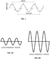
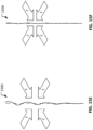
- FIG. 1 depicts a transverse wave which consists of oscillations occurring perpendicular or at right angles to the direction of the wave.
- the waves are composed of crests and troughs with a specific amplitude that determines the energy or force transmitted by each wave.
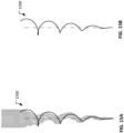
- the amount of energy carried by a wave is related to the amplitude of the wave. Putting more energy into a transverse pulse will not affect the wavelength, the frequency or the speed of the pulse. The energy imparted to a pulse will only affect the amplitude of that pulse. The more energy imparted to the wave, the higher will be the corresponding amplitude as illustrated by a comparison of the waves of FIGS. 2A and 2B . Conversely, lesser values of imparted energy produce smaller amplitudes.
- Eulerian angles are a set of angles used to describe the orientation of any object relative to a coordinate system.
- an object has an axis of rotational symmetry and two reference frames: a secondary coordinate system xyz, whose z-axis is coincident with the object's axis of symmetry, and an inertial primary coordinate system XYZ.
- FIG. 3 shows the object in an initial position. The body is then put through a series of rotations to establish the Eulerian angles as shown in FIG. 4 .
- the angles ⁇ and ⁇ specify the orientation of the secondary xyz system relative to the primary XYZ system.
- ⁇ (psi) is called the precession angle and ⁇ (theta) is called the nutation angle.
- the angle ⁇ (phi) specifies the rotation of the rigid body relative to the xyz system and is called the spin angle. These three angles are called the Eulerian angles.
- the precession rate is the rate at which the xyz system rotates about the Z-axis, the precession axis.
- the Eulerian angles can then be used to develop equations of angular motion which describe mathematically the behavior of a rotating body in precession.
- the scope of the mathematics is complex and does not need to be addressed here, however, a general idea of the resulting motion of a body in precession is provided in FIG. 5 .
- the body is rotating about its own axis, shown as R, while simultaneously rotating (precessing) about the central axis P.
- N represents the nutation of the body, which is a rocking or oscillation of the body itself as it precesses about the central axis, which can be considered negligible in this case.
- endodontic instruments that precess by off-setting the center of mass of the endodontic instrument from the center of rotation can be created in various ways. There are at least two fabrication methods that can be used to achieve this result.
- a first such fabrication method (“method 1") shifts the center of mass from the central axis, continuously, along its length using asymmetric cross-sections.
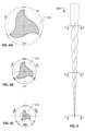
- An example of method 1 is shown by example endodontic instrument 600 in FIG. 6 .
- the endodontic instrument e.g., endodontic instrument 600
- the cross section of the endodontic instruments varies asymmetrically along the length of the central axis.
- the cross-sectional shape of endodontic instrument 600 is an equilateral triangle at cross-section A-A ( FIG. 6A ), and the cross-sectional shape increasingly becomes an isosceles triangle along the body of the instrument in the direction toward the tip (see FIGS. 6B and 6C ).
- This same concept can be applied utilizing instruments with other asymmetric cross-sections, for example a trapezoidal cross-section.
- bodily movement is a function of the asymmetry and centripetal force, which defines the precession angle.
- the cross-section of the endodontic instrument is symmetrical or bi-symmetrical and ground such that the center of mass of the cross-section is off-set at a distance away from the rotational axis.
- the off-set cross-section revolves around the central or rotational axis as it is being ground.
- the distance between the centers of mass (centroids) of the cross-sections (which are off-set from the axis of rotation, or "offset" for simplicity) and the central axis of rotation varies along the length of the endodontic instrument.
- This offset distance may increase or decrease monotonously or can accelerate.
- the offset can originate from the shank and extend progressively farther away from the central axis from the shank to the tip as depicted by endodontic instrument 700 ( FIG. 7 ), or originate at the tip and extend progressively farther away from the central axis from the tip to the shank as depicted by endodontic instrument 800 ( FIG. 8 ).
- FIG. 8 illustrates an endodontic instrument 800 that has a spiral or corkscrew shape/profile.
- the cross-sections shown in FIGS. 8A and 8B further illustrate the spiral/corkscrew configuration of the endodontic instrument 800.
- the center of mass of the cross-sections are offset from the axis of rotation, and the center of mass path spirals around the axis of rotation along the length of the endodontic instrument 800.
- the tip of the endodontic instrument 800 is centered on the axis of rotation of the endodontic instrument 800.
- FIG. 9 illustrates an example endodontic instrument 900 that has offset rectilinear cross sections that spiral around the axis of rotation (except at the tip where the cross-section in centered on the axis of rotation). For example, as shown in FIG. 9A , even the center of mass of the cross-section at the shank end of the working body of the instrument 900 is offset from the axis of rotation.
- An instrument design using this configuration will precess in both the x-axis and the y-axis, similar to the asymmetric cross-section, without necessarily displaying any bodily deflection.
- An offset rectilinear cross section such as this, can contribute to the innate flexibility of the endodontic instrument 900, while permitting intermittent cutting, which will mitigate cyclic fatigue.
- the larger clearance angles opposite the cutting flutes will facilitate hauling and elimination of debris, further improving the resistance to cyclic fatigue.
- FIGS. 10A and 10B are perspective images of the example endodontic instrument 900 demonstrating the spring, corkscrew, spiral, or coil-like configuration of the instrument 900 (and many other embodiments of the instruments described herein).
- the cross-section is off-set at a significant or "threshold distance" away from the central axis, as shown in FIGS. 10A and 10B , one can visualization of the radial/diametrical "compressibility" of the endodontic instruments (such as endodontic instrument 900 and other instruments described herein), which will be described further below.
- the design and fabrication method 2 i.e., grinding the instrument such that the centers of mass of the cross-sections are offset from the axis of rotation
- results in the cutting axis also referred to herein as the "center of mass path" being offset from, and spiraling around, the axis of rotation of the endodontic instrument while the instrument is in a natural condition (i.e., free from external stresses).
- the center of mass path 1141 spirals around the axis of rotation 1140.
- Axis 2 also becomes a precessional axis.
- the amount of off-set between the center/axis of rotation and the center of mass of the instrument's cross-sections is defined by the distance 1147 between these two axes 1140 and 1141, and varies along the entire length of the endodontic instrument 1110.
- the distance 1147 is maximum at the shank end (where the working body joins the shank) and gradually reduces along the working body (to zero at the tip, i.e., the tip is completely centered on the axis of rotation).
- the precessional axis also produces a transverse mechanical wave defined by a series of peaks and troughs.
- the amplitude or heights of the peaks are at a maximum when the endodontic instrument is in its free and unconstrained position.
- the peaks may be compressed. The amount of compression will depend upon the diameter and the curvature of the canal (ECS). Theoretically, when the endodontic instrument is fully compressed, the center of mass path 1141 will flatten out and be collinear with the axis of rotation 1140. As each peak along the endodontic instrument is elastically compressed, it behaves like a small spring and is a source of potential or stored energy.
- Stiffness and/or flexibility can be quantified using a parameter known as a spring constant ("k”), which is defined as the amount of force that is required to cause a unit of deformation.
- k F / ⁇ , where k equals the stiffness, F equals force and ⁇ equals displacement. Equations for the determination of the spring constant of actual mechanical systems are widely available in engineering literature. Due to the constantly changing cross section of an endodontic instrument of the designs described herein, the spring constant of the endodontic instruments will vary along their lengths. This spring constant, together with the endodontic instrument precession, directly affects the cutting forces applied to the surrounding root dentine during cutting.
- the spring condition along the entire length of the endodontic instrument will be considered.
- the tip of the endodontic instrument is in its unconstrained condition and sits at some distance from the central axis.
- the offset shank design e.g., FIGS. 8 , 9 , and 11 ) reverses the direction of the offset angle. The following discussion is applicable to both the offset tip and the offset shank designs.
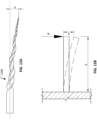
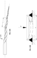
- FIG. 12A depicts an endodontic instrument 1200 with offset tip, which can be analyzed in general terms using the equations for a cantilevered beam as depicted in FIG. 12B .
- FIG. 12A an example endodontic instrument 1200 with offset tip design in its unconstrained condition is shown. If this endodontic instrument 1200 is inserted into a relatively straight endodontic cavity with a diameter that is narrower than the diameter of the endodontic instrument's cutting envelop, the endodontic instrument 1200 will be constrained along its length such that its axis of rotation and the central axis become more closely aligned. The resulting condition can be analyzed in general terms using the equations for a cantilever beam as depicted in FIG. 12B . As the endodontic instrument 1200 is rotated, the constrained or compressed endodontic instrument will expand and the coil-like structure will try to return to its unconstrained position.
- FIGS. 13A and 13B can be used to analyze a localized section L of the endodontic instrument 1200 as it bends to conform to the ECS during use.
- L is distance between the crest of two nodes, with which the spring rate of a single wave between the crests can be analyzed.
- FIG. 13B is a schematic of a simply supported beam where x is the maximum deflection,
- the localized section L of the endodontic instrument is analyzed using the terminology defined in the waveform discussion above, the spring rate k of a single wave crest between two nodes can be analyzed.
- L represents the distance between any two nodes
- I represents the moment of inertia which is dependent upon the cross sectional area of the endodontic instrument and will vary along its length
- E represents the modulus of elasticity (Young's Modulus), which is used to define the stiffness of different materials.
- this endodontic instrument 1200 When the initial conditions of this endodontic instrument 1200 as it is inserted into an ECS and undergoing radial constraining forces are evaluated, the reverse occurs of what is depicted in FIGS. 12A and 13A , that is, the instrument shown is those figures is in its unconstrained or uncompressed condition.
- F represents the force exerted on the endodontic instrument by the canal wall. Since the endodontic instrument is built with multiple nodes (crests and troughs) and potential deflections, the tendency of F will be to straighten out the endodontic instrument along its length. When the endodontic instrument is fully constrained, x, which represents the deflection of the endodontic instrument due to F would be zero (or nearly zero) and the cross-section of the endodontic instrument will be completely centered.
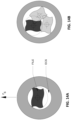
- FIG. 14A depicts the cross-section of the instrument when in its constrained or compressed condition.
- x which represents the deflection of the endodontic instrument due to F, would be zero or nearly zero.
- FIG. 14B demonstrates the endodontic instrument's inherent tendency to return to its natural or less-compressed state in which it is precessing about its central axis.
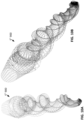
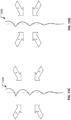
- FIGS. 15A through 15F An overview and schematic of an example spiral instrument 1500 in its entirety, as it transitions from its initial unconstrained condition to a completely constrained condition is shown in FIGS. 15A through 15F .
- the instrument 1500 In its completely unconstrained state ( FIG. 15A and B ), the instrument 1500 presents as a spiral, corkscrew, spring (e.g., a conical spring shape or a tornado spring shape), or coil-like structure, which is radially compressible as described herein.
- spring e.g., a conical spring shape or a tornado spring shape
- This phenomenon of diametric/radial compressibility can also facilitate the negotiation of more complicated anatomy, i.e., enable better maneuverability in narrowing or constricted and tortuous ECS architecture.
- endodontic instruments such as these are more compliant and will demonstrate better centering and less apical transportation, which will better preserve the original anatomy of the ECS.
- the moment of inertia is the capacity of a cross-section of a mass to resist distortion. It is considered with respect to a reference axis and how that cross-sectional area is distributed about the reference axis, usually a centroidal axis.
- A is the area of the plane of the cross-section and "y” is the distance between the centroid of the object and the central or x-axis.
- y is the distance between the centroid of the object and the central or x-axis.
- FIG. 16A is a schematic demonstrating the components of a lamina of an endodontic instrument with an offset center of mass and the components under consideration in applying the parallel axis theorem.
- I cm is the moment of inertia of a body of mass "m” with respect to a line through its centroid "cm.”
- I is the total moment of inertia with respect to a line parallel to the central axis or axis of rotation, and "d” is the distance between the two lines.
- a practical example of the parallel-axis theorem is a hammer rotating about an axis perpendicular to the handle. The farther the axis of rotation extends away from the head of the hammer, and toward the end of the handle, the greater the total inertia at the end of the hammer after it is released, rotates and strikes an opposing surface.
- b will be along the long axis of the rectangle (and the cutting axis) and in the second instance b will be represented by the shorter axis, the bending axis.
- the moment of inertia when b is along the shorter axis will be much less, which dictates this as the bending axis.
- an endodontic instrument with a rectangular cross-section rotates and enters a curved ECS, it will be continuously alternating between its two moments of inertia (between stiff and flexible positions). Due to lower stress on the endodontic instrument that is associated with the thinner cross section (smaller moment), the endodontic instrument will naturally tend to bend around this axis as it rounds the curve of a canal, but continually oriented such that the cutting blades remain in the long axis for maximum strength or resistance to distortion.
- FIG. 16C is a schematic of an offset rectilinear (in cross-sectional shape) endodontic instrument demonstrating the adjustability of the distance of the offset from central axis.
- the offset rectilinear cross-section as seen in FIG. 16C demonstrates how the mass of the endodontic instrument can be adjusted across any lamina, improving flexibility and resistance to cyclic fatigue.
- the endodontic instrument can be made more or less resistant to distortion or more or less flexible by increasing or decreasing the distance of the offset from the central axis.
- there is an optimum offset distance and orientation of the cross-section which offers both resistance to torsional failure and maximum flexibility.
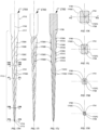
- FIGS. 17A-17V illustrate an implementation of an example endodontic instrument 1700 described herein.
- the endodontic instrument 1700 is shown in its natural shape (e.g., unaffected by external forces from the wall of the ECS).
- the endodontic instrument 1700 is shown in a radially constrained state (e.g., as a result of radially compressive forces from the wall of an ECS).
- the endodontic instrument 1700 includes four sides and edges, is rectilinear in transverse cross-section, and can be utilized to remove tissue and/or dentin from an ECS.
- the instrument 1700 includes a shank 1710 and a working portion 1712, which is tapered in a shank to tip direction.
- the tip 1713 includes an active or cutting surface, which is confluent with the working surface 1712.
- the leading tip 1713 can include a non-active or non-cutting surface, which is also confluent with the working surface 1712.
- the maximum flute diameter (MxFD) 1717 is located near the shank end 1711 of the cutting surface and the minimum flutes diameter (MnFD) 1716 is located near the tip 1713.
- the shank 1710 above the working portion 1712 is essentially cylindrical and exhibits a slightly larger diameter than the working surface 1712.
- a fitting which is suitable for an engine driven motor of a hand-piece and chuck, or a handle utilized for manual instrumentation, can be attached to the shank 1710.
- the center of mass path 1741 of the endodontic instrument 1700 spirals around the axis of rotation 1740.
- the offset is maximum where the working surface 1712 meets the shank 1710. From the position where the working surface 1712 meets the shank 1710, proceeding toward the tip 1713, the offset decreases.
- the offset at the tip 1713 is zero (i.e., the center of mass at the tip 1713 is on the axis of rotation).
- the endodontic instrument 1700 in an unconstrained state will have a conical outer profile when rotated about its axis of rotation 1740.
- FIGS. 17A-C there are four continuous helical flutes 1720A, 1720B, 1720C and 1720D, which are flats or grooves that follow the circumference of the working surface 1712, and spiral around the central axis 1740 toward the leading tip 1713.
- These flutes 1720A, 1720B, 1720C and 1720D may be equidistant from each other or become increasingly tighter or more numerous as they approach the tip 1713.
- Flutes 1720A, 1720B, 1720C and 1720D revolve around the central axis 1740 in either a right to left, or left to right direction.
- each flute 1720A, 1720B, 1720C and 1720D between the MxFD 1717 to the MnFD 1716 are not less than one and not greater than ten.
- Helical flutes 1720A, 1720B, 1720C and 1720D each originate at the MxFD 1717 at separate locations. Flutes 1720A and 1720C are substantially wider than flutes 1720B and 1720D. All flutes conform to the shape of a bi-symmetric rectilinear cross-section as shown in FIGS. 17D-17G , 17K-N , 17O and 17O-1 and 17S-V .
- Each flute 1720A, 1720B, 1720C and 1720D is continuous along the length of the cutting surface 1712 to the leading tip 1713.
- the flutes 1720A, 1720B, 1720C, and 1720D cooperate to form a web or core 1726, which is rectilinear (i.e,, rectangular in this example, but may alternatively be another four-sided shape such as a trapezoid or parallelogram).
- the web or core is outlined by areas of clearance designated by numerals 1730A, 1730B, 1730C, and 1730D (see FIG. 17O-1 ).
- the clearance areas 1730A, 1730B, 1730C, and 1730D can be of variable proportion and depth. Clearance areas 1730A, 1730B, 1730C, and 1730D are circumscribed by the perimeter of the cutting envelope 1743A (or 1743C).
- flutes 1720A, 1720B, 1720C, and 1720D intersect the periphery of the outer-most cutting envelope 1743A via cutting edge tips 1731A, 1731B, 1731C, and 1731D (depending on the offset).
- these intersections are at 75 degrees, 105 degrees, 75 degrees, and 105 degrees of separation, forming various rake angles with the cutting envelope 1743A.
- lines drawn connecting points 1731A, 1731B, 1731C, and 1731D form a bi-symmetrical rectangle.
- the difference in degrees between the widest flutes 1720A and 1720C and the narrowest flutes 1720B and 1720D is 30 degrees.
- cutting tips cutting edge tips 1731A, 1731B, 1731C, and 1731D can intersect the cutting envelope 1734A at differing angles by increasing or decreasing the distance between the widest and narrowest flutes, for example, 100 degrees verses 80 degrees etc.
- the outline of the rectilinear cross-section between cutting tips 1731A, 1731B, 1731C, and 1731D can vary.
- the difference in the number of degrees of separation between the widest flutes and narrowest flute should not be less than 5 degrees and not greater than 70 degrees.
- each flutes can vary, however, the cross-sectional diameter of the core portion 1726 should, in general, not be narrower than half or fifty percent of the cross sectional diameter of the instrument.
- FIGS. 17H-17N are a repetition of FIGS. 17A-G , but when the instrument 1700 is fully radially constrained, e.g., confined by the ECS prior to cutting.
- FIG. 17O and 17P-V the transition between an instrument that is a fully constrained and unconstrained can be visualized.
- the center of mass path 1741 of the endodontic instrument 1700 shifts from being aligned with the axis of rotation 1740 to being a spiral around the axis of rotation 1740 (as depicted in FIGS. 17A-17G ).
- the transition can be seen occurring in any cross-sectional view both horizontally and vertically, whereby the centroid corresponds to the axis of rotation when fully constrained and corresponds to the mass path 1741 ( FIG. 17P ) when unconstrained.
- distance 1744 the transition of the cross-sectional center of mass between a fully constrained endodontic instrument 1727C and unconstrained endodontic instrument 1727A is exemplified by distance 1744.
- distance 1744 When the instrument is unconstrained, distance 1744 generally decreases from shank to tip. During the transition the distance 1744 is variable and corresponds to the degree of constraint or relaxation of the endodontic instrument 1700 as it rotates.
- the clearance areas 1730A-D are continuously changing such that the cutting perimeter transitions (i.e., enlarges) from cutting perimeter 1743C (when fully constrained) to cutting perimeter 1743A (when unconstrained).
- the center of mass 1741 and the axis of rotation 1740 at the tip 1713 are coincident during both constrained ( FIG. 17N ) and unconstrained states ( FIG. 17G ).
- Other implementations are envisioned, which including a tip that maintains a constant distance away from the central axis or a variable distance.
- all cutting edge tips 1731A, 1731B, 1731C, and 1731D are in contact with the cutting periphery 1743C when the instrument 1700 is fully constrained.
- some cutting edge tips e.g., cutting edge tips 1731C and 1731D in this example
- cutting edge tips 1731A and 1731B are not performing any cutting.
- a quadrilateral cross-section with an offset center of mass has greater torsional inertia and the potential for better resistance to cyclic fatigue and breakage than an offset triangular cross-section.
- other quadrilateral implementations are also envisioned within the scope of this disclosure. These implementations may be particularly advantageous, if changes are also made in the modality of operation, for example, reciprocation verse rotation, speed and/or applied torque of rotation, and variations in the choice of materials for fabrication.
- Of particular interest are bi-symmetrical and asymmetrical trapezoidal cross-sections due to improvements in torsional inertia, which will be described further.
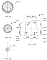
- FIGS. 18A through 18C illustrate an example trapezoidal cross-sectional shape implementation of an endodontic instrument 1800 described herein in its alternately unconstrained condition and in its radially constrained condition.
- FIG. 18D illustrates a detailed cross-sectional view of the endodontic instrument 1800.
- Such a trapezoidal cross-sectional shape has an offset center of mass (as a result of the trapezoidal shape) and the instrument 1800 overall (like other example instruments described above) has natural a spiral or corkscrew shape thereby leading to the center of mass of the cross-sections being offset from the axis of rotation for a second reason.
- FIGS. 18A through 18C the radially constrained condition is shown in dotted lines whereas the unconstrained condition is shown in solid lines and can be seen to expand into the shaded area (which represents an enlarged ECS diameter).
- the cross-section becomes continuously smaller/narrower from shank to tip, whereby the tip of the instrument (shown in FIG. 18C ) is completely centered on the axis of rotation and transitions into a symmetrical square cross-section.
- the endodontic instrument 1800 includes four corners/edges or cutting angles 1811, 1812, 1813, and 1814 and four sides.
- the sides of the depicted embodiment are S-shaped, but in some embodiments the sides are linear.
- Lines 1821, 1822, 1823, and 1824 are straight, linear lines that are drawn as extending between each pair of corners of the four corners 1811, 1812, 1813, and 1814.
- the lines 1811, 1812, 1813, and 1814 can be used to help describe the shape of the depicted cross-section.
- the depicted cross-sectional shape of the endodontic instrument 1800 is configured to represent a bi-symmetrical trapezoid (or an isosceles trapezoid) with a line of symmetry 1831 that bisects the trapezoid.
- the center of mass 1801 is closer to the long base (represented by line 1824) than to the short base (represented by line 1822).
- the endodontic instrument 1800 can be utilized to remove tissue and/or dentin from an endodontic cavity space (ECS) or root canal space.
- the cutting angles (the angles between the adjacent lines 1821, 1822, 1823, and 1824) are separated by 85° and 95° respectively, which can be modified, but must be less than or greater than 90°.
- the four sides cooperate to form a web or core portion with a center of mass 1801, which is separate and offset from the axis of rotation.
- orientation of the cutting flutes pits the long base of the trapezoid (represented by the line 1824) against the walls of the ECS.
- corners 1811 and 1814 are the primary cutting edges.
- all four corners 1811, 1812, 1813, and 1814 may be in contact with the wall of the ECS.
- the sides of the trapezoid also called splines, may be configured to be straight (linear), or S-shaped (as shown) or a variety of other shapes useful in cutting and carrying or hauling debris away from the working surface and leading tip.
- the depth and height of each flute can vary, however, the cross-sectional diameter of the core portion should, in general, not be narrower than half or fifty percent of the cross-sectional diameter of the instrument 1800.
- FIGS. 19A-19K illustrates an implementation of an endodontic instrument 1900 described herein in its alternately unconstrained and constrained condition.
- the cross-section of the endodontic instrument 1900 in its radially constrained condition is shown is dashed lines, whereas the unconstrained condition is shown in solids lines (and can be seen to expand into the shaded area representing the ECS after some enlargement by the endodontic instrument 1900).
- the endodontic instrument 1900 includes four corners/edges or cutting angles 1911, 1912, 1913, and 1914 and four sides.
- the sides of the depicted embodiment are S-shaped, but in some embodiments the sides are linear or have another shape.
- the dashed lines 1921, 1922, 1923, and 1924 are straight, linear lines that are drawn as extending between each pair of corners of the four corners 1911, 1912, 1913, and 1914.
- the lines 1921, 1922, 1923, and 1924 can be used to help describe the completely asymmetrical shape of the depicted cross-section.
- the four corners/edges 1911, 1912, 1913, and 1914 are positioned relative to each other such that lines 1921, 1922, 1923, and 1924 that drawn between each pair of adjacent corners of the four corners 1911, 1912, 1913, and 1914 results in four lines 1921, 1922, 1923, and 1924 that have no parallelism nor perpendicularity relative to each other. That is, no two lines of the four lines 1921, 1922, 1923, and 1924 are parallel to each other, and no two lines of the four lines 1921, 1922, 1923, and 1924 are perpendicular to each other.
- the line 1922 can corresponding to a first side of the cross-sectional shape of the endodontic instrument 1900.
- the line 1923 can correspond to a second side of the cross-sectional shape of the endodontic instrument 1900.
- the line 1924 can correspond to a third side of the cross-sectional shape of the endodontic instrument 1900.
- the line 1921 can correspond to a fourth side of the cross-sectional shape of the endodontic instrument 1900.
- the second side is longer than the first side; the third side is longer than the second side; and the fourth side is longer than the third side.
- the endodontic instrument 1900 is configured with a cross-sectional shape that is known as a trapezium (a quadrilateral with no parallel sides) or a general irregular quadrilateral.
- the endodontic instrument 1900 can be utilized to remove tissue and/or dentin from an endodontic cavity space (ECS) or root canal space.
- ECS endodontic cavity space
- the cutting angles between joining lines of the four lines 1921, 1922, 1923, and 1924 are separated by dissimilar degrees. In this instance the sides and resultant cutting angles are separated by 80°, 85°, 83° and 112° respectively, which can be modified, but must all be less than or greater than 90°.
- the four sides cooperate to form a web or core portion with a center of mass 1901, which is separate and offset from the axis of rotation (due to the asymmetrical cross-section).
- the orientation of the cutting flutes pits the side the trapezoid represented by line 19s4 against the walls of the ECS (endodontic cavity space) or root canal space. That is, the two corners 1911 and 1914 are the primary cutting points/edges of the endodontic instrument 1900 (whereas the other corners/edges 1912 and 1913 are out of contact with the wall of the ECS). However, when the endodontic instrument 1900 is fully radially constrained within the ECS, then the three corners 1911, 1912, and 1914 are the cutting points/edges of the endodontic instrument 1900 (whereas the other corner 1913 is out of contact with the wall of the ECS).
- the two primary cutting points/edges of the endodontic instrument 1900 are the pair of adjacent corners between which the third side (represented by line 1924) extends.
- the three cutting points/edges (the three corners 1911, 1912, and 1914) of the endodontic instrument 1900 that are in contact with the wall of the ECS when the endodontic instrument 1900 is in the fully radially constrained configuration are the corners between which the third side (represented by line 1924) extends and between which the fourth side (represented by line 1921) extends.
- the sides of the endodontic instrument 1900 may be configured to be straight (linear), or S-shaped (as shown), or variety of other shapes useful in cutting and carrying or hauling debris away from the working surface and leading tip.
- the depth and height of each flute can vary, however, the cross-sectional diameter of the core portion should, in general, not be narrower than half or fifty percent of the cross-sectional diameter of the instrument 1900.
- the endodontic instrument 1900 is shown in its natural or unconstrained condition.
- the instrument 1900 includes a shank 1911 and a working portion 1912, which is tapered in a shank to tip direction.
- the tip 1913 includes an active or cutting surface, which is confluent with the working surface 1912.
- the leading tip 1913 can include a non-active or non-cutting surface, which is also confluent with the working surface 1912.
- the maximum flute diameter (MxFD) 1917 is located near the shank end of the cutting surface and the minimum flutes diameter (MnFD) 1916 is located near the tip.
- the shank is essentially cylindrical and exhibits a slightly larger diameter than the working surface.
- a fitting which is suitable for an engine driven motor of a hand piece and chuck, or a handle utilized for manual instrumentation, can be attached to the shank.
- the center of mass path 1941 of the endodontic instrument 1900 spirals around the axis of rotation 1940.
- the centers of mass of the cross-sections are offset from the axis of rotation for two reasons: (i) because the cross-sectional shape is a trapezium (a quadrilateral with no parallel sides) or a general irregular quadrilateral and (ii) because the profile of the endodontic instrument 1900 is spiral or corkscrew shaped.
- the offset is maximum where the working surface 1912 meets the shank 1910. From the position where the working surface 1912 meets the shank 1910, proceeding toward the tip 1917 the offset decreases.
- the offset at the tip 1913 is zero, i.e., the center of mass at the tip 1913 is on and coincides with the axis of rotation.
- the endodontic instrument 1900 in an unconstrained state will trace out a conical shape when rotated about its axis of rotation 1940.
- each flute 1920A, 1920B, 1920C and 1920D there are four continuous helical flutes 1920A, 1920B, 1920C and 1920D, which present as grooves that follow the circumference of the working surface 1912, and spiral around the central axis 1940 toward the leading tip 1913.
- These four flutes 1920A, 1920B, 1920C and 1920D may maintain the same spacing per unit length, also known as pitch, or become increasingly tighter or more numerous as they approach the tip.
- Flutes 1920A, 1920B, 1920C and 1920D revolve around the central axis 1940 in either a right to left or left to right direction.
- the total number of revolutions of each flute 1920A, 1920B, 1920C and 1920D between the MxFD 1919 to the MnFD 1916 are not less than one and not greater than ten.
- flutes 1920A, 1920B, 1920C and 1920D intersect the periphery of the outer-most cutting envelope 1943A via cutting edges 1931A, 1931B, 1931C, and 1931D.
- these intersections are at 80 degrees, 112 degrees, 83 degrees, and 85 degrees of separation, forming various rake angles with the cutting envelope 1943A.
- lines drawn connecting the cutting angles 1931A, 1931B, 1931C, and 1931D form a trapezium (a quadrilateral with no parallel sides) or a general irregular quadrilateral.
- the center of mass path 1941 of the endodontic instrument 1900 shifts from being nearly aligned with the axis of rotation 1940 (except for the offset from the cross-sectional shape) to spiraling around the axis of rotation 1940 to a greater extent (as a result of both the cross-sectional shape and the spiral or corkscrew profile).
- the transition can be seen occurring in any cross-sectional view both horizontally and vertically.
- FIGS. 20A through 20C illustrates an implementation of an endodontic instrument with a cross-sectional shape (having asymmetric trapezoidal, trapezium, or general irregular quadrilateral cross-sectional shapes), that is similar to 19A-K but is configured and fabricated such that the longest side (the fourth side) of the asymmetrical trapezoidal cross-section is in contact with the wall of the ECS.
- a cross-sectional shape having asymmetric trapezoidal, trapezium, or general irregular quadrilateral cross-sectional shapes
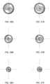
- FIGS. 21A-28C illustrate three cross-sectional views of each type of endodontic instrument of multiple types of endodontic instruments (i.e., having various cross-sectional shapes such as triangular, rectangular, parallelogram, etc.). Three figures (“A,” "B,” and “C") are provided for each type of endodontic instrument.
- FIGS. 21A-28C shows the arrangement of the instrument's cross-section in relation to the ECS wall in two ways. That is: (i) the cross-section shown in solid lines corresponds to when the instrument is not fully radially constrained, and (ii) the cross-section shown in dashed lines corresponds to when the instrument is fully radially constrained.
- the concentric dashed line circles bounding the gray ring shown in FIGS. 21A-28C represent two different diameters of the ECS wall.
- the inner dashed circle represents the ECS wall when the ECS is small in relation to the natural state of the endodontic instrument, such that the ECS fully radially constrains (compresses) the endodontic instrument.
- the outer dashed circle represents the ECS wall when the ECS is larger in diameter, such that the ECS does not fully radially constrain or compress the endodontic instrument.
- each type of endodontic instrument ( FIGS. 21B, 21C , 22B, 22C , 23B, 23C , 24B, 24C , 25B, 25C , 26B, 26C , 27B, 27C , 28B, and 28C ) are cross-sections taken along the working body of the respective endodontic instruments.
- the tip of the endodontic instrument(s) has a center of mass that is coincident with the instrument's axis of rotation (both when the instrument is fully radially constrained and when the instrument is not fully radially constrained).
- the tip of the endodontic instrument(s) has a center of mass that is offset from the instrument's axis of rotation when the instrument is not fully radially constrained, and that is coincident with the instrument's axis of rotation when the instrument is fully radially constrained.
- FIGS. 21A-21C illustrate an S-splined offset rectangular cross-section with two cutting edges that are on the same side, but are positioned along the narrowest flutes of the cross-section. This configuration would offer improved cutting ability, but would necessarily be less resistant the torsional failure.
- FIGS. 22A-22C illustrate an offset rhomboidal cross-section with two cutting edges on opposite sides (when fully radially constrained). This implementation should be as resistant to torsional inertia as a rectangular cross-section, but may be more useful when designed for use in reciprocation or a reciprocating hand piece.
- FIGS. 23A-23C illustrate an offset rectilinear cross-section that is square with two cutting edges in the same side.
- This cross-section may be used singly or in combination with other rectilinear cross-sections that are more rectangular.
- an instrument may retain a rectangular or rhomboidal cross-section from shank to tip, but become increasing square and end square at the tip. The tip of this would necessarily have greater torsional inertia than a rectangular tip due to the increase in the surface area itself, however, instruments with a square cross-section may be less compliant or flexible than those with rectangular cross-sections given a similar cutting envelop.
- FIGS. 24A-24C illustrate an offset square cross-section with S-shaped spines.
- An S-shaped spline may be more useful during cutting than a straight spline due to an improved relief angles and clearance angles.
- an instrument with a square cross-section may be have greater torsional inertia, but be less complaint or flexible than a rectangular or rhomboidal cross-sections.
- a hybridization of a rectangular and/or rhomboidal cross-section and a square cross-section from shank to tip is also envisioned.
- FIGS. 25A-25C illustrate an offset trapezoidal cross-section with two cutting edges on the same side and along the widest cutting flute.
- cross-sections that are both offset and asymmetric have the potential for display excellent precessional cutting ability, but may be slightly predisposed to chatter.
- Instruments with four cutting edges, however, are more stable than instruments with three cutting edges and display less chatter.
- FIGS. 26A-26C illustrate an offset cross-section of a "hatchet" configuration.
- a cross-section similar to this would be useful is an endodontic cavity preparation where a reciprocating hand piece was employed.
- FIGS. 27A-27C illustrate an offset biangular and bisymmetrical cross-section with S-shaped splines. This design may possess all the attributes of a four side cross-section with similar base and height, however, the reduced number of cutting edgesmay mitigate its cutting ability. This design would also be useful in reciprocation.
- FIGS. 28A-28C illustrate an offset triangular cross-section with broad radial lands.
- Cross-sections similar to this have also been termed U-endodontic instruments, which refers to the U-shaped clearance areas.
- the radial lands add bulk to the cross-section and, in turn, will add strength and appreciable resistance to torsional failure.
- Instruments with cross-section similar to these, however, will have efficient cutting and hauling characteristic due the increased surface tension created by the lands themselves.
- Endodontic instrument compressibility is independent of the elasticity or compressibility of the material the endodontic instrument is made from. As discussed above, these characteristics are dependent on a design that has a precessional cutting axis, which is ground in or inscribed into the working portion of the instrument. A "snap shot" taken of the endodontic instrument as it rotates in a root canal shows an instrument proendodontic instrument with multiple crests and troughs (when the instrument is not fully radially compressed).
Landscapes
- Health & Medical Sciences (AREA)
- General Health & Medical Sciences (AREA)
- Dentistry (AREA)
- Veterinary Medicine (AREA)
- Public Health (AREA)
- Epidemiology (AREA)
- Life Sciences & Earth Sciences (AREA)
- Oral & Maxillofacial Surgery (AREA)
- Animal Behavior & Ethology (AREA)
- Biomedical Technology (AREA)
- Surgery (AREA)
- Nuclear Medicine, Radiotherapy & Molecular Imaging (AREA)
- Engineering & Computer Science (AREA)
- Neurosurgery (AREA)
- Neurology (AREA)
- Dental Tools And Instruments Or Auxiliary Dental Instruments (AREA)
Claims (15)
- Instrument endodontique (1900) pour la préparation d'un espace de cavité endodontique, l'instrument endodontique comprenant :une tige (1911) configurée pour être fixée à un moteur afin d'entraîner l'instrument endodontique autour d'un premier axe (1940) ; etun corps en forme de spirale ayant un profil en forme de tire-bouchon s'étendant sur une certaine longueur à partir de la tige, le corps en forme de spirale étant plein et présentant : i) une extrémité de tige où se rejoignent le corps en forme de spirale et la tige et ii) une extrémité de pointe, au moins une partie du corps en forme de spirale étant effilée de telle sorte que l'extrémité de pointe ait un diamètre (1916) qui est inférieur à un diamètre (1917) de l'extrémité de tige, le corps en forme de spirale comprenant une pluralité de sections transversales, chaque section transversale ayant un centre de masse et comprenant :quatre côtés etquatre coins (1911, 1912, 1913, 1914), dans lequel chaque coin des quatre coins se trouve à la jonction de deux côtés adjacents des quatre côtés, dans lequel les quatre coins sont positionnés l'un par rapport à l'autre de telle sorte que des lignes droites (1921, 1922, 1923, 1924) tracées entre chaque paire de coins adjacents des quatre coins donnent quatre lignes droites qui ne sont ni parallèles ni perpendiculaires les unes par rapport aux autres et qui définissent des angles aigus au niveau de trois coins des quatre coins,le corps en forme de spirale ayant une trajectoire de centre de masse (1941) définie par les centres de masse de la pluralité de sections transversales du corps en forme de spirale, dans lequel au moins une partie de la trajectoire de centre de masse entre l'extrémité de pointe et l'extrémité de tige s'enroule en spirale autour du premier axe le long du premier axe.
- Instrument endodontique selon la revendication 1, dans lequel chaque côté des quatre côtés est en forme de S, ou dans lequel chaque côté des quatre côtés est linéaire.
- Instrument endodontique selon la revendication 1 ou 2, dans lequel les quatre côtés comprennent :un premier côté ;un deuxième côté qui est plus long que le premier côté ;un troisième côté qui est plus long que le deuxième côté ; etun quatrième côté qui est plus long que le troisième côté.
- Instrument endodontique selon la revendication 3, dans lequel le corps en forme de spirale est configuré de telle sorte que lorsque l'instrument endodontique est entraîné dans l'espace de la cavité endodontique autour du premier axe et dans un état radialement non contraint, au niveau de chaque section transversale d'au moins une partie de la longueur du corps en forme de spirale, seuls deux coins des quatre coins sont en contact avec une paroi de l'espace de la cavité endodontique.
- Instrument endodontique selon la revendication 4, dans lequel les deux coins sont la paire de coins adjacents entre lesquels s'étend le troisième côté.
- Instrument endodontique selon la revendication 5, dans lequel le corps en forme de spirale est configuré de telle sorte que lorsque l'instrument endodontique est entraîné dans l'espace de la cavité endodontique autour du premier axe et dans un état radialement contraint, au niveau de chaque section transversale d'au moins la partie de la longueur du corps en forme de spirale, seuls trois coins des quatre coins sont en contact avec la paroi de l'espace de la cavité endodontique.
- Instrument endodontique selon la revendication 6, dans lequel les trois coins sont des coins entre lesquels s'étend le troisième côté et entre lesquels s'étend le quatrième côté.
- Instrument endodontique selon la revendication 4, dans lequel les deux coins des quatre coins qui sont en contact avec la paroi de l'espace de la cavité endodontique sont la paire de coins adjacents entre lesquels s'étend le quatrième côté.
- Instrument endodontique selon la revendication 8, dans lequel le corps en forme de spirale est configuré de telle sorte que lorsque l'instrument endodontique est entraîné dans l'espace de la cavité endodontique autour du premier axe et dans un état radialement contraint, au niveau de chaque section transversale d'au moins la partie de la longueur du corps en forme de spirale, seuls trois coins des quatre coins sont en contact avec la paroi de l'espace de la cavité endodontique.
- Instrument endodontique selon la revendication 9, dans lequel les trois coins sont des coins entre lesquels s'étend le troisième côté et entre lesquels s'étend le quatrième côté.
- Instrument endodontique selon la revendication 3, dans lequel un premier angle défini entre le premier côté et le deuxième côté est obtus, dans lequel un deuxième angle défini entre le deuxième côté et le troisième côté est aigu, dans lequel un troisième angle défini entre le troisième côté et le quatrième côté est aigu, et dans lequel un quatrième angle défini entre le quatrième côté et le premier côté est aigu.
- Instrument endodontique selon l'une quelconque des revendications 1 à 11, dans lequel la pluralité de sections transversales comprend une section transversale au niveau de l'extrémité de pointe qui a un centre de masse qui coïncide avec le premier axe.
- Instrument endodontique selon l'une quelconque des revendications 1 à 11, dans lequel la pluralité de sections transversales comporte une première section transversale et une seconde section transversale, dans lequel la première section transversale a une première géométrie, et dans lequel la seconde section transversale a une seconde géométrie différente de la première géométrie.
- Instrument endodontique selon l'une quelconque des revendications 1 à 11, dans lequel chaque section transversale entre la première section transversale et la seconde section transversale présente une géométrie changeant progressivement l'une par rapport à l'autre.
- Instrument endodontique selon l'une quelconque des revendications 1 à 11, dans lequel la pluralité de sections transversales comprend une première section transversale et une seconde section transversale, dans lequel un centre de masse de la première section transversale est éloigné du premier axe d'une première distance, dans lequel un centre de masse de la seconde section transversale est éloigné du premier axe d'une seconde distance, et dans lequel la première distance est supérieure à la seconde distance.
Applications Claiming Priority (1)
| Application Number | Priority Date | Filing Date | Title |
|---|---|---|---|
| US18/215,693 US11980521B1 (en) | 2023-06-28 | 2023-06-28 | Endodontic instruments |
Publications (3)
| Publication Number | Publication Date |
|---|---|
| EP4483835A1 EP4483835A1 (fr) | 2025-01-01 |
| EP4483835C0 EP4483835C0 (fr) | 2025-05-07 |
| EP4483835B1 true EP4483835B1 (fr) | 2025-05-07 |
Family
ID=90038437
Family Applications (1)
| Application Number | Title | Priority Date | Filing Date |
|---|---|---|---|
| EP24158900.1A Active EP4483835B1 (fr) | 2023-06-28 | 2024-02-21 | Instruments endodontiques |
Country Status (2)
| Country | Link |
|---|---|
| US (3) | US11980521B1 (fr) |
| EP (1) | EP4483835B1 (fr) |
Families Citing this family (1)
| Publication number | Priority date | Publication date | Assignee | Title |
|---|---|---|---|---|
| US11980521B1 (en) | 2023-06-28 | 2024-05-14 | Michael J. Scianamblo | Endodontic instruments |
Family Cites Families (17)
| Publication number | Priority date | Publication date | Assignee | Title |
|---|---|---|---|---|
| US5984679A (en) * | 1997-09-26 | 1999-11-16 | Ormco Corporation | Method of manufacturing superelastic endodontic files and files made therefrom |
| US6299445B1 (en) * | 1999-04-08 | 2001-10-09 | Ormco Corporation | Endodontic instrument, instrument blank and method of manufacture |
| US7249414B2 (en) * | 1999-09-10 | 2007-07-31 | Micro Mega, S.A. | Method for making a root canal instrument |
| FR2821000B1 (fr) * | 2001-02-20 | 2003-08-22 | Jean Claude Rouiller | Instrument d'alesage, en particulier pour l'alesage de canaux dentaires |
| US20040023186A1 (en) * | 2002-05-16 | 2004-02-05 | Mcspadden John T. | Multi-tapered endodontic file |
| DE10233030B3 (de) * | 2002-07-20 | 2004-02-19 | Gebr. Brasseler Gmbh & Co. Kg | Wurzelkanalinstrument |
| US7094056B2 (en) | 2003-05-01 | 2006-08-22 | Scianamblo Michael J | Endodontic instrument having reversed helix |
| US7955078B2 (en) | 2003-05-01 | 2011-06-07 | Scianamblo Michael J | Endodontic instruments for preparing endodontic cavity spaces |
| DE202004007925U1 (de) * | 2004-05-17 | 2004-08-19 | Gebr. Brasseler Gmbh & Co. Kg | Wurzelkanalinstrumentenset |
| EP1709934B1 (fr) | 2005-04-08 | 2011-03-30 | Michael J. Scianamblo | Instruments endodontiques pliables |
| USD750246S1 (en) | 2006-04-10 | 2016-02-23 | Michael J. Scianamblo | Endodontic device |
| FR2971932B1 (fr) * | 2011-02-25 | 2014-01-17 | Micro Mega Int Mfg Sa | Instrument canalaire du type alesoir. |
| WO2014118587A1 (fr) * | 2013-01-30 | 2014-08-07 | Maillefer Instruments Holding Sàrl | Instrument pour l'alésage des canaux radiculaires dentaires |
| US9901418B2 (en) * | 2013-06-20 | 2018-02-27 | DENTSPLY SIRONA, Inc. | Endodontic instruments |
| US10595961B2 (en) * | 2017-03-27 | 2020-03-24 | Michael J. Scianamblo | Endodontic instruments displaying compressibility |
| CN111098101B (zh) * | 2020-01-15 | 2023-12-12 | 江苏盛玛特新材料科技有限公司 | 一种新型根管锉加工工艺及根管锉 |
| US11980521B1 (en) | 2023-06-28 | 2024-05-14 | Michael J. Scianamblo | Endodontic instruments |
-
2023
- 2023-06-28 US US18/215,693 patent/US11980521B1/en active Active
-
2024
- 2024-02-21 EP EP24158900.1A patent/EP4483835B1/fr active Active
- 2024-04-26 US US18/647,470 patent/US12426989B2/en active Active
-
2025
- 2025-09-05 US US19/320,518 patent/US20260000481A1/en active Pending
Also Published As
| Publication number | Publication date |
|---|---|
| US20260000481A1 (en) | 2026-01-01 |
| US20250000614A1 (en) | 2025-01-02 |
| US12426989B2 (en) | 2025-09-30 |
| EP4483835C0 (fr) | 2025-05-07 |
| EP4483835A1 (fr) | 2025-01-01 |
| US11980521B1 (en) | 2024-05-14 |
Similar Documents
| Publication | Publication Date | Title |
|---|---|---|
| US11944513B2 (en) | Endodontic instruments displaying compressibility | |
| US11607290B2 (en) | Endodontic instruments | |
| US8496476B2 (en) | Endodontic instruments for preparing endodontic cavity spaces | |
| US6942484B2 (en) | Critical path endodontic instruments for preparing endodontic cavity spaces | |
| US20260000481A1 (en) | Endodontic instruments | |
| CN107530102A (zh) | 用于超声乳化的扭转模式针 | |
| KR19990072083A (ko) | 치내요법 기구 | |
| JP2007038007A (ja) | トルク要求を減少させた歯内治療リーマー/ファイル | |
| HK1096837B (en) | Bending endodontic instruments |
Legal Events
| Date | Code | Title | Description |
|---|---|---|---|
| PUAI | Public reference made under article 153(3) epc to a published international application that has entered the european phase |
Free format text: ORIGINAL CODE: 0009012 |
|
| STAA | Information on the status of an ep patent application or granted ep patent |
Free format text: STATUS: REQUEST FOR EXAMINATION WAS MADE |
|
| 17P | Request for examination filed |
Effective date: 20240221 |
|
| AK | Designated contracting states |
Kind code of ref document: A1 Designated state(s): AL AT BE BG CH CY CZ DE DK EE ES FI FR GB GR HR HU IE IS IT LI LT LU LV MC ME MK MT NL NO PL PT RO RS SE SI SK SM TR |
|
| GRAP | Despatch of communication of intention to grant a patent |
Free format text: ORIGINAL CODE: EPIDOSNIGR1 |
|
| STAA | Information on the status of an ep patent application or granted ep patent |
Free format text: STATUS: GRANT OF PATENT IS INTENDED |
|
| GRAS | Grant fee paid |
Free format text: ORIGINAL CODE: EPIDOSNIGR3 |
|
| GRAA | (expected) grant |
Free format text: ORIGINAL CODE: 0009210 |
|
| STAA | Information on the status of an ep patent application or granted ep patent |
Free format text: STATUS: THE PATENT HAS BEEN GRANTED |
|
| INTG | Intention to grant announced |
Effective date: 20250320 |
|
| AK | Designated contracting states |
Kind code of ref document: B1 Designated state(s): AL AT BE BG CH CY CZ DE DK EE ES FI FR GB GR HR HU IE IS IT LI LT LU LV MC ME MK MT NL NO PL PT RO RS SE SI SK SM TR |
|
| REG | Reference to a national code |
Ref country code: GB Ref legal event code: FG4D |
|
| REG | Reference to a national code |
Ref country code: CH Ref legal event code: EP |
|
| REG | Reference to a national code |
Ref country code: DE Ref legal event code: R096 Ref document number: 602024000103 Country of ref document: DE |
|
| REG | Reference to a national code |
Ref country code: IE Ref legal event code: FG4D |
|
| U01 | Request for unitary effect filed |
Effective date: 20250604 |
|
| U07 | Unitary effect registered |
Designated state(s): AT BE BG DE DK EE FI FR IT LT LU LV MT NL PT RO SE SI Effective date: 20250611 |
|
| PG25 | Lapsed in a contracting state [announced via postgrant information from national office to epo] |
Ref country code: ES Free format text: LAPSE BECAUSE OF FAILURE TO SUBMIT A TRANSLATION OF THE DESCRIPTION OR TO PAY THE FEE WITHIN THE PRESCRIBED TIME-LIMIT Effective date: 20250507 |
|
| PG25 | Lapsed in a contracting state [announced via postgrant information from national office to epo] |
Ref country code: NO Free format text: LAPSE BECAUSE OF FAILURE TO SUBMIT A TRANSLATION OF THE DESCRIPTION OR TO PAY THE FEE WITHIN THE PRESCRIBED TIME-LIMIT Effective date: 20250807 Ref country code: GR Free format text: LAPSE BECAUSE OF FAILURE TO SUBMIT A TRANSLATION OF THE DESCRIPTION OR TO PAY THE FEE WITHIN THE PRESCRIBED TIME-LIMIT Effective date: 20250808 |
|
| PG25 | Lapsed in a contracting state [announced via postgrant information from national office to epo] |
Ref country code: PL Free format text: LAPSE BECAUSE OF FAILURE TO SUBMIT A TRANSLATION OF THE DESCRIPTION OR TO PAY THE FEE WITHIN THE PRESCRIBED TIME-LIMIT Effective date: 20250507 |
|
| PG25 | Lapsed in a contracting state [announced via postgrant information from national office to epo] |
Ref country code: HR Free format text: LAPSE BECAUSE OF FAILURE TO SUBMIT A TRANSLATION OF THE DESCRIPTION OR TO PAY THE FEE WITHIN THE PRESCRIBED TIME-LIMIT Effective date: 20250507 |
|
| PG25 | Lapsed in a contracting state [announced via postgrant information from national office to epo] |
Ref country code: RS Free format text: LAPSE BECAUSE OF FAILURE TO SUBMIT A TRANSLATION OF THE DESCRIPTION OR TO PAY THE FEE WITHIN THE PRESCRIBED TIME-LIMIT Effective date: 20250807 |
|
| PG25 | Lapsed in a contracting state [announced via postgrant information from national office to epo] |
Ref country code: IS Free format text: LAPSE BECAUSE OF FAILURE TO SUBMIT A TRANSLATION OF THE DESCRIPTION OR TO PAY THE FEE WITHIN THE PRESCRIBED TIME-LIMIT Effective date: 20250907 |
|
| PG25 | Lapsed in a contracting state [announced via postgrant information from national office to epo] |
Ref country code: SM Free format text: LAPSE BECAUSE OF FAILURE TO SUBMIT A TRANSLATION OF THE DESCRIPTION OR TO PAY THE FEE WITHIN THE PRESCRIBED TIME-LIMIT Effective date: 20250507 |
|
| PG25 | Lapsed in a contracting state [announced via postgrant information from national office to epo] |
Ref country code: CZ Free format text: LAPSE BECAUSE OF FAILURE TO SUBMIT A TRANSLATION OF THE DESCRIPTION OR TO PAY THE FEE WITHIN THE PRESCRIBED TIME-LIMIT Effective date: 20250507 |
|
| PG25 | Lapsed in a contracting state [announced via postgrant information from national office to epo] |
Ref country code: SK Free format text: LAPSE BECAUSE OF FAILURE TO SUBMIT A TRANSLATION OF THE DESCRIPTION OR TO PAY THE FEE WITHIN THE PRESCRIBED TIME-LIMIT Effective date: 20250507 |
|
| PLBE | No opposition filed within time limit |
Free format text: ORIGINAL CODE: 0009261 |
|
| STAA | Information on the status of an ep patent application or granted ep patent |
Free format text: STATUS: NO OPPOSITION FILED WITHIN TIME LIMIT |
|
| REG | Reference to a national code |
Ref country code: CH Ref legal event code: L10 Free format text: ST27 STATUS EVENT CODE: U-0-0-L10-L00 (AS PROVIDED BY THE NATIONAL OFFICE) Effective date: 20260318 |
|
| U20 | Renewal fee for the european patent with unitary effect paid |
Year of fee payment: 3 Effective date: 20260209 |
|
| 26N | No opposition filed |
Effective date: 20260210 |