EP4483848A2 - Meniskusallotransplantattransplantationssystem und verfahren zur verwendung - Google Patents
Meniskusallotransplantattransplantationssystem und verfahren zur verwendung Download PDFInfo
- Publication number
- EP4483848A2 EP4483848A2 EP24185327.4A EP24185327A EP4483848A2 EP 4483848 A2 EP4483848 A2 EP 4483848A2 EP 24185327 A EP24185327 A EP 24185327A EP 4483848 A2 EP4483848 A2 EP 4483848A2
- Authority
- EP
- European Patent Office
- Prior art keywords
- guidewire
- hole
- guide
- diameter
- reamer
- Prior art date
- Legal status (The legal status is an assumption and is not a legal conclusion. Google has not performed a legal analysis and makes no representation as to the accuracy of the status listed.)
- Pending
Links
Images



Classifications
-
- A—HUMAN NECESSITIES
- A61—MEDICAL OR VETERINARY SCIENCE; HYGIENE
- A61B—DIAGNOSIS; SURGERY; IDENTIFICATION
- A61B17/00—Surgical instruments, devices or methods
- A61B17/14—Surgical saws
- A61B17/15—Guides therefor
-
- A—HUMAN NECESSITIES
- A61—MEDICAL OR VETERINARY SCIENCE; HYGIENE
- A61B—DIAGNOSIS; SURGERY; IDENTIFICATION
- A61B17/00—Surgical instruments, devices or methods
- A61B17/16—Instruments for performing osteoclasis; Drills or chisels for bones; Trepans
- A61B17/1604—Chisels; Rongeurs; Punches; Stamps
-
- A—HUMAN NECESSITIES
- A61—MEDICAL OR VETERINARY SCIENCE; HYGIENE
- A61B—DIAGNOSIS; SURGERY; IDENTIFICATION
- A61B17/00—Surgical instruments, devices or methods
- A61B17/16—Instruments for performing osteoclasis; Drills or chisels for bones; Trepans
- A61B17/1613—Component parts
- A61B17/1622—Drill handpieces
-
- A—HUMAN NECESSITIES
- A61—MEDICAL OR VETERINARY SCIENCE; HYGIENE
- A61B—DIAGNOSIS; SURGERY; IDENTIFICATION
- A61B17/00—Surgical instruments, devices or methods
- A61B17/16—Instruments for performing osteoclasis; Drills or chisels for bones; Trepans
- A61B17/1635—Instruments for performing osteoclasis; Drills or chisels for bones; Trepans for grafts, harvesting or transplants
-
- A—HUMAN NECESSITIES
- A61—MEDICAL OR VETERINARY SCIENCE; HYGIENE
- A61B—DIAGNOSIS; SURGERY; IDENTIFICATION
- A61B17/00—Surgical instruments, devices or methods
- A61B17/16—Instruments for performing osteoclasis; Drills or chisels for bones; Trepans
- A61B17/1659—Surgical rasps, files, planes, or scrapers
-
- A—HUMAN NECESSITIES
- A61—MEDICAL OR VETERINARY SCIENCE; HYGIENE
- A61B—DIAGNOSIS; SURGERY; IDENTIFICATION
- A61B17/00—Surgical instruments, devices or methods
- A61B17/16—Instruments for performing osteoclasis; Drills or chisels for bones; Trepans
- A61B17/1662—Instruments for performing osteoclasis; Drills or chisels for bones; Trepans for particular parts of the body
- A61B17/1675—Instruments for performing osteoclasis; Drills or chisels for bones; Trepans for particular parts of the body for the knee
-
- A—HUMAN NECESSITIES
- A61—MEDICAL OR VETERINARY SCIENCE; HYGIENE
- A61F—FILTERS IMPLANTABLE INTO BLOOD VESSELS; PROSTHESES; DEVICES PROVIDING PATENCY TO, OR PREVENTING COLLAPSING OF, TUBULAR STRUCTURES OF THE BODY, e.g. STENTS; ORTHOPAEDIC, NURSING OR CONTRACEPTIVE DEVICES; FOMENTATION; TREATMENT OR PROTECTION OF EYES OR EARS; BANDAGES, DRESSINGS OR ABSORBENT PADS; FIRST-AID KITS
- A61F2/00—Filters implantable into blood vessels; Prostheses, i.e. artificial substitutes or replacements for parts of the body; Appliances for connecting them with the body; Devices providing patency to, or preventing collapsing of, tubular structures of the body, e.g. stents
- A61F2/02—Prostheses implantable into the body
- A61F2/30—Joints
- A61F2/46—Special tools for implanting artificial joints
- A61F2/4644—Preparation of bone graft, bone plugs or bone dowels, e.g. grinding or milling bone material
-
- A—HUMAN NECESSITIES
- A61—MEDICAL OR VETERINARY SCIENCE; HYGIENE
- A61L—METHODS OR APPARATUS FOR STERILISING MATERIALS OR OBJECTS IN GENERAL; DISINFECTION, STERILISATION OR DEODORISATION OF AIR; CHEMICAL ASPECTS OF BANDAGES, DRESSINGS, ABSORBENT PADS OR SURGICAL ARTICLES; MATERIALS FOR BANDAGES, DRESSINGS, ABSORBENT PADS OR SURGICAL ARTICLES
- A61L27/00—Materials for grafts or prostheses or for coating grafts or prostheses
- A61L27/36—Materials for grafts or prostheses or for coating grafts or prostheses containing ingredients of undetermined constitution or reaction products thereof, e.g. transplant tissue, natural bone, extracellular matrix
- A61L27/3604—Materials for grafts or prostheses or for coating grafts or prostheses containing ingredients of undetermined constitution or reaction products thereof, e.g. transplant tissue, natural bone, extracellular matrix characterised by the human or animal origin of the biological material, e.g. hair, fascia, fish scales, silk, shellac, pericardium, pleura, renal tissue, amniotic membrane, parenchymal tissue, fetal tissue, muscle tissue, fat tissue, enamel
- A61L27/3612—Cartilage, synovial fluid
-
- A—HUMAN NECESSITIES
- A61—MEDICAL OR VETERINARY SCIENCE; HYGIENE
- A61B—DIAGNOSIS; SURGERY; IDENTIFICATION
- A61B17/00—Surgical instruments, devices or methods
- A61B2017/00969—Surgical instruments, devices or methods used for transplantation
-
- A—HUMAN NECESSITIES
- A61—MEDICAL OR VETERINARY SCIENCE; HYGIENE
- A61B—DIAGNOSIS; SURGERY; IDENTIFICATION
- A61B90/00—Instruments, implements or accessories specially adapted for surgery or diagnosis and not covered by any of the groups A61B1/00 - A61B50/00, e.g. for luxation treatment or for protecting wound edges
- A61B90/03—Automatic limiting or abutting means, e.g. for safety
- A61B2090/033—Abutting means, stops, e.g. abutting on tissue or skin
- A61B2090/034—Abutting means, stops, e.g. abutting on tissue or skin abutting on parts of the device itself
-
- A—HUMAN NECESSITIES
- A61—MEDICAL OR VETERINARY SCIENCE; HYGIENE
- A61F—FILTERS IMPLANTABLE INTO BLOOD VESSELS; PROSTHESES; DEVICES PROVIDING PATENCY TO, OR PREVENTING COLLAPSING OF, TUBULAR STRUCTURES OF THE BODY, e.g. STENTS; ORTHOPAEDIC, NURSING OR CONTRACEPTIVE DEVICES; FOMENTATION; TREATMENT OR PROTECTION OF EYES OR EARS; BANDAGES, DRESSINGS OR ABSORBENT PADS; FIRST-AID KITS
- A61F2/00—Filters implantable into blood vessels; Prostheses, i.e. artificial substitutes or replacements for parts of the body; Appliances for connecting them with the body; Devices providing patency to, or preventing collapsing of, tubular structures of the body, e.g. stents
- A61F2/02—Prostheses implantable into the body
- A61F2/28—Bones
- A61F2002/2892—Tibia
-
- A—HUMAN NECESSITIES
- A61—MEDICAL OR VETERINARY SCIENCE; HYGIENE
- A61M—DEVICES FOR INTRODUCING MEDIA INTO, OR ONTO, THE BODY; DEVICES FOR TRANSDUCING BODY MEDIA OR FOR TAKING MEDIA FROM THE BODY; DEVICES FOR PRODUCING OR ENDING SLEEP OR STUPOR
- A61M25/00—Catheters; Hollow probes
- A61M25/01—Introducing, guiding, advancing, emplacing or holding catheters
- A61M25/09—Guide wires
- A61M2025/09175—Guide wires having specific characteristics at the distal tip
- A61M2025/09183—Guide wires having specific characteristics at the distal tip having tools at the distal tip
-
- A—HUMAN NECESSITIES
- A61—MEDICAL OR VETERINARY SCIENCE; HYGIENE
- A61M—DEVICES FOR INTRODUCING MEDIA INTO, OR ONTO, THE BODY; DEVICES FOR TRANSDUCING BODY MEDIA OR FOR TAKING MEDIA FROM THE BODY; DEVICES FOR PRODUCING OR ENDING SLEEP OR STUPOR
- A61M25/00—Catheters; Hollow probes
- A61M25/01—Introducing, guiding, advancing, emplacing or holding catheters
- A61M25/09—Guide wires
- A61M25/09041—Mechanisms for insertion of guide wires
Definitions
- This disclosure relates to a device and systems for use in a meniscal allograft transplantation procedure.
- Meniscal allograft transplantation is a common technique for total replacement of a tom lateral or medial meniscus.
- One type of meniscal allograft transplantation utilizes a trapezoidal bone block commonly known as a dovetail meniscal allograft.
- a dovetail meniscal allograft Such an allograft must be cut to a precise shape.
- the range in allograft sizes in addition to the geometry of the bone makes cutting of the dovetail meniscal allograft difficult to do by hand.
- an improved system that cuts the dovetail shape with greater precision to create an allograft that will better fit into the recipient site, effectively decreasing implant failure and improving patient results, is desirable.
- meniscal allograft transplantation requires reaming one or more areas of the tibial bone of the patient to make room for the allograft using a meniscal guide system. Detecting the depth a reamer has penetrated through the tibial bone can be difficult.
- existing meniscal guide systems may lack features to prevent surgeons from drilling beyond the tibial bone into a sensitive region of nerves and/or arteries. Accordingly, an improved system incorporating one or more hard stops that prevent the surgeon from drilling past the tibial bone and effectively prevents damage to the nerves and/or arteries of the patient may be desirable.
- the disclosure herein includes a meniscal allograft transplantation system and methods of use.
- the present disclosure provides a device for use in a meniscal allograft transplantation procedure.
- the device includes a first sidewall and a second sidewall spaced away from the first sidewall at a fixed distance.
- the device also includes a moveable wall positioned between the first sidewall and the second sidewall.
- the device also includes an adjustment member coupled to the moveable wall. The adjustment member is configured to alter a distance between the moveable wall and the first sidewall.
- the device also includes a fixed cutting guide including a first slot.
- the fixed cutting guide is fixed with respect to the first sidewall.
- the device also includes a first removable cutting guide including a second slot and a third slot.
- the first removable cutting guide is configured to be removably coupled to the first sidewall and/or the second sidewall.
- the device also includes a second removable cutting guide including a fourth slot.
- the second removable cutting guide is configured to be removably coupled to the first sidewall and/or the second sidewall.
- the present disclosure provides a system for use in a meniscal allograft transplantation procedure.
- the system can include a first guide block including a first through hole, a second through hole, a third through hole, and a fourth through hole.
- the system can also include a first guidewire configured to be positioned through the first through hole.
- the system can also include a second guidewire configured to be positioned through the second through hole.
- the system can also include a third guidewire configured to be positioned through the third through hole.
- the third guidewire includes a first portion having a first diameter and a second portion having a second diameter that is less than the first diameter.
- the system can also include a fourth guidewire configured to be positioned through the fourth through hole.
- the fourth guidewire includes a first portion having a first diameter and a second portion having a second diameter that is less than the first diameter.
- the system can also include a first hard stop feature configured to be positioned over the third guidewire.
- the first hard stop feature has an inner diameter greater than the second diameter of the third guidewire but less than the first diameter of the third guidewire.
- the system can also include a second hard stop feature configured to be positioned over the fourth guidewire.
- the second hard stop feature has an inner diameter greater than the second diameter of the fourth guidewire but less than the first diameter of the fourth guidewire.
- the system can also include a second guide block including at least one through hole configured to receive a guidewire. Such a guide block can include at least two, three, four, or five through holes configured to receive a guidewire.
- the system can also include a second guide block including a first through hole configured to receive the first guidewire, a second through hole configured to receive the second guidewire, a third through hole configured to receive the third guidewire, and a fourth through hole configured to receive the fourth guidewire.
- the second guide block is configured to contact the first hard stop feature and the second hard stop feature.
- the system also includes a first reamer configured to be positioned over the first guidewire and through the first through hole of the second guide block.
- the first reamer includes a third hard stop feature having a diameter greater than a diameter of the first through hole of the second guide block.
- the system also includes a second reamer configured to be positioned over the second guidewire and through the second through hole of the second guide block.
- the second reamer includes a fourth hard stop feature having a diameter greater than a diameter of the second through hole of the second guide block.
- the present disclosure provides a system for use in a meniscal allograft transplantation procedure.
- the system includes a handle, a guide base coupled to the handle, and a guidewire hole guide removably coupled to the guide base.
- the system also includes a first guidewire having a first end and a second end opposite the first end.
- the first end of the first guidewire is configured to be positioned through a first through hole in the guidewire hole guide.
- the first guidewire includes a first hard stop feature positioned between the first end and the second end of the first guidewire.
- the first hard stop feature has a diameter greater than a diameter of the first through hole.
- the first guidewire includes a reduced diameter portion between the first hard stop feature and the first end of the first guidewire.
- the system also includes a second guidewire having a first end and a second end opposite the first end.
- the first end of the second guidewire is configured to be positioned through a second through hole in the guidewire hole guide.
- the second guidewire includes a second hard stop feature positioned between the first end and the second end of the second guidewire.
- the second hard stop feature has a diameter greater than a diameter of the second through hole.
- the second guidewire includes a reduced diameter portion between the second hard stop feature and the second end of the second guidewire.
- the system also includes a first reamer having a first end and a second end opposite the first end. The first end of the first reamer is configured to be positioned over the first guidewire and through the first through hole of the guidewire hole guide.
- the first reamer includes a third hard stop feature adjacent the second end of the first reamer.
- the system also includes a second reamer having a first end and a second end opposite the first end. The first end of the second reamer is configured to be positioned over the second guidewire and through the second through hole of the guidewire hole guide.
- the second reamer includes a fourth hard stop feature adjacent the second end of the second reamer.
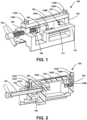
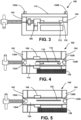
- Figures 1-5 illustrate a device 100 for use in a meniscal allograft transplantation procedure.
- the device 100 includes a first sidewall 102 and a second sidewall 104 spaced away from the first sidewall 102 at a fixed distance.
- the device 100 also includes a moveable wall 106 positioned between the first sidewall 102 and the second sidewall 104.
- the device 100 also includes an adjustment member 108 coupled to the moveable wall 106.
- the adjustment member 108 is configured to alter a distance between the moveable wall 106 and the first sidewall 102.
- the device 100 also includes a fixed cutting guide 110 including a first slot 112. The fixed cutting guide 110 is fixed with respect to the first sidewall 102.
- the device 100 also includes a first removable cutting guide 114 including a second slot 116 and a third slot 118.
- the first removable cutting guide 114 is configured to be removably coupled to the first sidewall 102 and/or the second sidewall 104.
- the device 100 also includes a second removable cutting guide 120 including a fourth slot 122.
- the second removable cutting guide 120 is configured to be removably coupled to the first sidewall 102 and/or the second sidewall 104.
- the adjustment member 108 comprises a threaded rod 124.
- a rotation of the threaded rod 124 in a first direction moves the moveable wall 106 closer to the first sidewall 102
- a rotation of the threaded rod 124 in a second direction moves the moveable wall 106 further from the first sidewall 102.
- the device 100 further includes a first set of teeth 126A coupled to the first sidewall 102, and a second set of teeth 126B coupled to the moveable wall 106.
- the first set of teeth 126A are removably coupled to the first sidewall 102
- the second set of teeth 126B are removably coupled to the moveable wall 106.
- the first set of teeth 126A and the second set of teeth 126B attach to the first sidewall 102 and the moveable wall 106 with a bolt or other similar coupling mechanism that can be unscrewed to release the first set of teeth 126A and the second set of teeth 126B. This permits easy replacement of the first set of teeth 126A and the second set of teeth 126B as they are worn down, creating a more economical design that only requires two small components to be replaced rather than the entire device.
- the device 100 further includes a rasp surface 128 positioned on a top surface of the fixed cutting guide 110.
- the rasp surface 128 may be used to file down rough edges of the meniscal allograft left by the sawblade, as discussed in additional detail below.
- the length of the rasp surface 128 spans the largest allografts needed, allowing the user to file down an edge on a perfectly flat plane and remove material uniformly. This helps maintain the evenness of the surfaces as well as the geometry of the allograft.
- first removable cutting guide 114 and the second removable cutting guide 120 are removably coupled to the first sidewall 102 and the second sidewall 104 via a first threaded connector 130A and a second threaded connector 130B.
- first removable cutting guide 114 includes a first pin 132A configured to be positioned in a first hole 134A in the first sidewall 102, and the first removable cutting guide 114 includes a second pin 132B configured to be positioned in a second hole 134B in the second sidewall 104.
- the second removable cutting guide 120 includes a first pin 136A configured to be positioned in the first hole 134A in the first sidewall 102, and the second removable cutting guide 120 includes a second pin 136B configured to be positioned in the second hole 134B in the second sidewall 104.
- the first pins 132A, 136A and the second pins 132B, 136B in each of the first removable cutting guide 114 and the second removable cutting guide 120 may help align the first removable cutting guide 114 and the second removable cutting guide 120 prior to removably coupling those features to the first sidewall 102 and the second sidewall 104 via the threaded connectors.
- the first slot 112 is positioned substantially perpendicular to the second slot 116, and the fourth slot 122 is positioned at a non-zero angle with respect to the second slot 116 such that the second slot 116 and the fourth slot 122 are not perpendicular.
- a meniscal allograft is positioned between the first set of teeth 126A and the second set of teeth 126B, and the adjustment member 108 is used to move the moveable wall 106 closer to the first sidewall 102 to thereby secure the meniscal allograft in place.
- the surgeon makes a first cut with a saw through the first slot 112 to create a bottom cut on the allograft. This allows the creation of a flat surface for the bottom feature of the trapezoidal shape of a dovetail allograft.
- the surgeon positions the first removable cutting guide 114 onto the device 100.
- the larger third slot 118 is used to hold the meniscus out of the way of the cut.
- the surgeon then makes a second cut with a saw through the second slot 116 that is a vertical cut substantially perpendicular to the first cut.
- the surgeon removes the first removable cutting guide 114 and positions the second removable cutting guide 120 onto the device 100.
- the surgeon makes a third cut with a saw through the fourth slot 122 that is angled with respect to the second cut to finish creating the trapezoidal shape of the allograft.
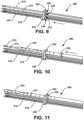
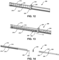
- Figures 6-14 illustrate a system 200 for use in a meniscal allograft transplantation procedure.
- the system 200 includes a first guide block 202 including a first through hole 204, a second through hole 206, a third through hole 208, and a fourth through hole 210.
- the system 200 also includes a first guidewire 212 configured to be positioned through the first through hole 204.
- the system also includes a second guidewire 214 configured to be positioned through the second through hole 206.
- the system 200 also includes a third guidewire 216 configured to be positioned through the third through hole 208.
- the third guidewire 216 includes a first portion having a first diameter and a second portion having a second diameter that is less than the first diameter.
- the system 200 also includes a fourth guidewire 218 configured to be positioned through the fourth through hole 210.
- the fourth guidewire 218 includes a first portion having a first diameter and a second portion having a second diameter that is less than the first diameter.
- the system 200 also includes a first hard stop feature 220 configured to be positioned over the third guidewire 216.
- the first hard stop feature 220 has an inner diameter greater than the second diameter of the third guidewire 216 but less than the first diameter of the third guidewire 216.
- the system 200 also includes a second hard stop feature 222 configured to be positioned over the fourth guidewire 218.
- the second hard stop feature 222 has an inner diameter greater than the second diameter of the fourth guidewire 218 but less than the first diameter of the fourth guidewire 218.
- the first hard stop feature 220 and the second hard stop feature 222 each include a ring or a nut.
- the system 200 also includes a second guide block 224 including a first through hole 226 configured to receive the first guidewire 212, a second through hole 228 configured to receive the second guidewire 214, a third through hole 230 configured to receive the third guidewire 216, and a fourth through hole 232 configured to receive the fourth guidewire 218.
- the second guide block 224 is configured to contact the first hard stop feature 220 and the second hard stop feature 222.
- the system 200 also includes a first reamer 234 configured to be positioned over the first guidewire 212 and through the first through hole 226 of the second guide block 224.
- the first reamer 234 includes a third hard stop feature 236 having a diameter greater than a diameter of the first through hole 226 of the second guide block 224.
- the system 200 also includes a second reamer 238 configured to be positioned over the second guidewire 214 and through the second through hole 228 of the second guide block 224.
- the second reamer 238 includes a fourth hard stop feature 240 having a diameter greater than a diameter of the second through hole 228 of the second guide block 224.
- the third guidewire 216 comprises a slotted guidewire such that the second portion of the third guidewire 216 includes a first flat portion and a second flat portion opposite the first flat portion.
- the fourth guidewire 218 comprises a slotted guidewire such that the second portion of the fourth guidewire 218 includes a first flat portion and a second flat portion opposite the first flat portion.
- the first through hole 204 of the first guide block 202, the second through hole 206 of the first guide block 202, the third through hole 208 of the first guide block 202, and the fourth through hole 210 of the first guide block 202 are equal.
- a diameter of the first reamer 234 is less than a diameter of the second reamer 238.
- the diameter of the first reamer 234 is about 6mm, and the diameter of the second reamer 238 is about 7 mm.
- the first guidewire 212 and the second guidewire 214 are positioned through the first through hole 204 and the second through hole 206 of the first guide block 202, respectively, and into the tibial bone of the patient to a desired depth.
- the third guidewire 216 and the fourth guidewire 218 are positioned through the third through hole 208 and the fourth through hole 210 of the first guide block 202, respectively, and into the tibial bone of the patient to the desired depth so that they align with the desired depth of the first guidewire 212 and the second guidewire 214.
- the first hard stop feature 220 is positioned over the second portion of the third guidewire 216 and moved along the third guidewire 216 until the first hard stop feature 220 meets the first portion of the third guidewire 216.
- the first hard stop feature 220 cannot be pushed any further along the third guidewire 216.
- the second hard stop feature 222 is positioned over the second portion of the fourth guidewire 218 and moved along the fourth guidewire 218 until the second hard stop feature 222 meets the first portion of the fourth guidewire 218. Since the diameter of the first portion of the fourth guidewire 218 is greater than an inner diameter of the second hard stop feature 222, the second hard stop feature 222 cannot be pushed any further along the fourth guidewire 218.
- the second guide block 224 is positioned over each of the first guidewire 212, the second guidewire 214, the third guidewire 216, and the fourth guidewire 218 as shown in Figure 9 until the second guide block 224 reaches the first hard stop feature 220 and the second hard stop feature 222 and cannot be pushed any further.
- the first reamer 234 is then positioned over the first guidewire 212 and drilled until the third hard stop feature 236 of the first reamer 234 contacts the second guide block 224.
- the third hard stop feature 236 has a diameter greater than a diameter of the first through hole 226 of the second guide block 224.
- the second reamer 238 is then positioned over the second guidewire 214 and drilled until the fourth hard stop feature 240 of the second reamer 238 contacts the second guide block 224.
- the fourth hard stop feature 240 has a diameter greater than a diameter of the second through hole 228 of the second guide block 224. All parts of the system 200 may then be removed from the patient.
- Figures 15-18 illustrate another system 300 for use in a meniscal allograft transplantation procedure.
- the system 300 includes a handle 302, a guide base 304 coupled to the handle 302, and a guidewire hole guide 306 removably coupled to the guide base 304.
- the system 300 also includes a marking hook shaft 308 coupled to the guide base 304.
- the system 300 also includes a first guidewire 310 having a first end 312 and a second end 314 opposite the first end 312. The first end 312 of the first guidewire 310 is configured to be positioned through a first through hole 316 in the guidewire hole guide 306.
- the first guidewire 310 includes a first hard stop feature 318 positioned between the first end 312 and the second end 314 of the first guidewire 310.
- the first hard stop feature 318 has a diameter greater than a diameter of the first through hole 316.
- the first guidewire 310 includes a reduced diameter portion between the first hard stop feature 318 and the first end 312 of the first guidewire 310.
- the system 300 also includes a second guidewire 320 having a first end 322 and a second end 324 opposite the first end 322.
- the first end 322 of the second guidewire 320 is configured to be positioned through a second through hole 326 in the guidewire hole guide 306.
- the second guidewire 320 includes a second hard stop feature 328 positioned between the first end 322 and the second end 324 of the second guidewire 320.
- the second hard stop feature 328 has a diameter greater than a diameter of the second through hole 326.
- the second guidewire 320 includes a reduced diameter portion between the second hard stop feature 328 and the second end 324 of the second guidewire 320.
- the system 300 also includes a first reamer 330 having a first end 332 and a second end 334 opposite the first end 332.
- the first end 332 of the first reamer 330 is configured to be positioned over the first guidewire 310 and through the first through hole 316 of the guidewire hole guide 306.
- the first reamer 330 includes a third hard stop feature 336 adjacent the second end 334 of the first reamer 330.
- the system 300 also includes a second reamer 338 having a first end 340 and a second end 342 opposite the first end 340.
- the first end 340 of the second reamer 338 is configured to be positioned over the second guidewire 320 and through the second through hole 326 of the guidewire hole guide 306.
- the second reamer 338 includes a fourth hard stop feature 344 adjacent the second end 342 of the second reamer 338.
- a diameter of the first reamer 330 is less than a diameter of the second reamer 338. In one such example, the diameter of the first reamer 330 is about 6mm, and wherein the diameter of the second reamer 338 is about 7 mm.
- the guidewire hole guide 306 includes a first plurality of teeth 346A configured to interact with a second plurality of teeth 346B on the guide base 304 to provide a variety of rotational arrangements between the guidewire hole guide 306 and the guide base 304 and further to prevent rotation of the guidewire hole guide 306 with respect to the guide base 304.
- a first plurality of teeth 346A configured to interact with a second plurality of teeth 346B on the guide base 304 to provide a variety of rotational arrangements between the guidewire hole guide 306 and the guide base 304 and further to prevent rotation of the guidewire hole guide 306 with respect to the guide base 304.
- Such an arrangement permits the formation of a left- and right-winged dovetail.
- the guidewire hole guide 306 can be inserted into the guide base 304 in two positions by rotating about its center axis and aligning the arrow on the guide base 304 with the position marks.
- the first plurality of teeth 346A and the second plurality of teeth 346B ensure the guidewire hole guide 306 and the guide base 304 are locked at the desired angle and unable to rotate freely.
- the guide base 304 includes a canted coil spring 348 to removably couple the guidewire hole guide 306 to the guide base 304.
- the canted coil spring 348 creates a snap-lock mechanism that secures the guidewire hole guide 306 in place. This prevents the guidewire hole guide 306 and the guide base 304 from separating while still permitting the user to disassemble it later for bidirectional use.
- the system 300 is locked in place, and the first through hole 316 of the guidewire hole guide 306 is aligned with a single channel 350 on the guide base 304.
- the reduced diameter portion of the first guidewire 310 is positioned adjacent the first hard stop feature 318, and the reduced diameter portion of the second guidewire 320 is positioned adjacent the second hard stop feature 328.
- the guide base 304 includes a first through hole 352 aligned with the first through hole 316 of the guidewire hole guide 306 when the guidewire hole guide 306 is removably coupled to the guide base 304, and the guide base 304 includes a second through hole 354 aligned with the second through hole 326 of the guidewire hole guide 306 when the guidewire hole guide 306 is removably coupled to the guide base 304.
- a surgeon uses a point on the marking hook shaft 308 of the system 300 to locate the edge of the tibia-the furthest point that will be drilled.
- the guidewire hole guide 306 is connected to the guide base 304 at the desired position (as discussed above in relation to Figure 16 ).
- the surgeon can then drill the first guidewire 310 through the first through hole 316 in the guidewire hole guide 306 and drill the second guidewire 320 through the second through hole 326 in the guidewire hole guide 306.
- the hard stop features on the drill guide prevents overdrilling past the tibia.
- the first hard stop feature 318 may comprise a ring feature that is wider than the diameter of the first through hole 316 in the guidewire hole guide 306.
- the first hard stop feature 328 may comprise a ring feature that is wider than the diameter of the second through hole 326 in the guidewire hole guide 306.
- the first hard stop feature 318 and the second hard stop feature 328 create a precise point at which the surgeon cannot drill past.
- the the first hard stop feature 318 and the second hard stop feature 328 perfectly align the tip of the first guidewire 310 and the second guidewire 320, respectively, with the point of the marking hook shaft 308.
- the first guidewire 310 and the second guidewire 320 may each include a thinned diameter located before the first hard stop feature 318 and the second hard stop feature 328, respectively.
- the entire guide system (excluding the first guidewire 310 and the second guidewire 320) can then be removed from the patient.
- the surgeon can then ream over the first guidewire 310 and the second guidewire 320 with the respective cannulated reamers to create the dovetail-shaped slot in the tibia.
- the surgeon reams over the first guidewire 310 with the smaller diameter first reamer 330 and over the second guidewire 320 with the larger diameter second reamer 338.
- the first reamer 330 has a third hard stop feature 336 and the fourth reamer 338 has fourth hard stop feature 344.
- the third hard stop feature 336 and the fourth hard stop feature 344 each comprise a pin inserted at the end of the first reamer 330 and second reamer 338, respectively.
- the third hard stop feature 336 stops the surgeon from drilling beyond the end of the snapped first guidewire 310 since the third hard stop feature 336 contacts the end of the snapped first guidewire 310 when the first reamer 330 reaches the desired depth.
- the fourth hard stop feature 344 stops the surgeon from drilling beyond the end of the snapped second guidewire 320 since the fourth hard stop feature 344 contacts the end of the snapped second guidewire 320 when the second reamer 338 reaches the desired depth.
- the third hard stop feature 336 and the fourth hard stop feature 344 perfectly aligns the end of the first reamer 330 and the second reamer 338, respectively, with the point of the marking hook shaft 308, preventing overdrilling into the neurons behind the tibia.
- Example methods and systems are described herein. It should be understood that the words “example,” “exemplary,” and “illustrative” are used herein to mean “serving as an example, instance, or illustration.” Any example or feature described herein as being an “example,” being “exemplary,” or being “illustrative” is not necessarily to be construed as preferred or advantageous over other examples or features. The examples described herein are not meant to be limiting. It will be readily understood that the aspects of the present disclosure, as generally described herein, and illustrated in the figures, can be arranged, substituted, combined, separated, and designed in a wide variety of different configurations, all of which are explicitly contemplated herein.
- Coupled means associated directly as well as indirectly.
- a member A may be directly associated with a member B, or may be indirectly associated therewith, e.g., via another member C. It will be understood that not all relationships among the various disclosed elements are necessarily represented.
- first, second, etc. are used herein merely as labels, and are not intended to impose ordinal, positional, or hierarchical requirements on the items to which these terms refer. Moreover, reference to, e.g., a “second” item does not require or preclude the existence of, e.g., a "first” or lower-numbered item, and/or, e.g., a "third" or higher-numbered item.
- references herein to "one embodiment” or “one example” or “an example” means that one or more feature, structure, or characteristic described in connection with the example is included in at least one implementation.
- the phrases “one embodiment” or “one example” or “an example” in various places in the specification may or may not be referring to the same example.
- a system, apparatus, structure, article, element, component, or hardware “configured to” perform a specified function is indeed capable of performing the specified function without any alteration, rather than merely having potential to perform the specified function after further modification.
- the system, apparatus, structure, article, element, component, or hardware “configured to” perform a specified function is specifically selected, created, implemented, utilized, programmed, and/or designed for the purpose of performing the specified function.
- "configured to” denotes existing characteristics of a system, apparatus, structure, article, element, component, or hardware which enable the system, apparatus, structure, article, element, component, or hardware to perform the specified function without further modification.
- a system, apparatus, structure, article, element, component, or hardware described as being “configured to” perform a particular function may additionally or alternatively be described as being “adapted to” and/or as being “operative to” perform that function.
Landscapes
- Health & Medical Sciences (AREA)
- Life Sciences & Earth Sciences (AREA)
- Surgery (AREA)
- Biomedical Technology (AREA)
- Engineering & Computer Science (AREA)
- Veterinary Medicine (AREA)
- Oral & Maxillofacial Surgery (AREA)
- Animal Behavior & Ethology (AREA)
- General Health & Medical Sciences (AREA)
- Public Health (AREA)
- Heart & Thoracic Surgery (AREA)
- Orthopedic Medicine & Surgery (AREA)
- Molecular Biology (AREA)
- Nuclear Medicine, Radiotherapy & Molecular Imaging (AREA)
- Medical Informatics (AREA)
- Dentistry (AREA)
- Transplantation (AREA)
- Chemical & Material Sciences (AREA)
- Cardiology (AREA)
- Vascular Medicine (AREA)
- Physical Education & Sports Medicine (AREA)
- Urology & Nephrology (AREA)
- Zoology (AREA)
- Botany (AREA)
- Chemical Kinetics & Catalysis (AREA)
- Dermatology (AREA)
- Medicinal Chemistry (AREA)
- Epidemiology (AREA)
- Prostheses (AREA)
- Materials For Medical Uses (AREA)
Applications Claiming Priority (1)
| Application Number | Priority Date | Filing Date | Title |
|---|---|---|---|
| US202363511254P | 2023-06-30 | 2023-06-30 |
Publications (2)
| Publication Number | Publication Date |
|---|---|
| EP4483848A2 true EP4483848A2 (de) | 2025-01-01 |
| EP4483848A3 EP4483848A3 (de) | 2025-02-12 |
Family
ID=91737883
Family Applications (1)
| Application Number | Title | Priority Date | Filing Date |
|---|---|---|---|
| EP24185327.4A Pending EP4483848A3 (de) | 2023-06-30 | 2024-06-28 | Meniskusallotransplantattransplantationssystem und verfahren zur verwendung |
Country Status (2)
| Country | Link |
|---|---|
| US (2) | US12588914B2 (de) |
| EP (1) | EP4483848A3 (de) |
Cited By (1)
| Publication number | Priority date | Publication date | Assignee | Title |
|---|---|---|---|---|
| US20230372123A1 (en) * | 2022-05-23 | 2023-11-23 | Amir A Jamali | Bone Cutting System and Apparatus |
Family Cites Families (35)
| Publication number | Priority date | Publication date | Assignee | Title |
|---|---|---|---|---|
| US6676662B1 (en) * | 1999-10-20 | 2004-01-13 | Sulzer Spine-Tech Inc. | Bone instruments and methods |
| US6648894B2 (en) * | 2000-12-21 | 2003-11-18 | Stryker Spine | Bone graft forming guide and method of forming bone grafts |
| US6355045B1 (en) | 2000-12-28 | 2002-03-12 | Depuy Orthopaedics, Inc. | Method and apparatus for surgically preparing a tibia for implantation of a prosthetic implant component which has an offset stem |
| US20190038298A1 (en) | 2001-05-25 | 2019-02-07 | Conformis, Inc. | Patient Selectable Joint Arthroplasty Devices and Surgical Tools |
| US7124762B2 (en) | 2002-08-15 | 2006-10-24 | Arthrex, Inc. | Dovetail meniscal allograft technique and system |
| US7780668B2 (en) * | 2007-03-02 | 2010-08-24 | Musculoskeletal Transplant Foundation | Osteochondral allograft cartilage transplant workstation |
| US7722608B2 (en) * | 2007-03-02 | 2010-05-25 | Musculoskeletal Transplant Foundation | Allograft implant workstation |
| US7955336B2 (en) * | 2007-04-13 | 2011-06-07 | Warsaw Orthopedic, Inc. | Cutting instrument and method of use for preparing an osteochondral plug for implantation |
| US8475534B2 (en) | 2008-02-29 | 2013-07-02 | Arthrex, Inc. | Canine elbow repair and instrumentation |
| US20090312801A1 (en) | 2008-06-16 | 2009-12-17 | Lemoine Jeremy J | Multi-guide plate holder |
| US8808297B2 (en) | 2009-02-24 | 2014-08-19 | Microport Orthopedics Holdings Inc. | Orthopedic surgical guide |
| US8840619B2 (en) | 2009-04-02 | 2014-09-23 | Arthrex, Inc. | Dovetail method of allograft transplantation |
| US8852197B2 (en) | 2011-06-30 | 2014-10-07 | Depuy (Ireland) | Surgical instrument assemblies for use in surgically preparing a tibia for implantation of a prosthetic component |
| US8795284B2 (en) * | 2011-10-13 | 2014-08-05 | Musculoskeletal Transplant Foundation | Instrumentation for repair of meniscus tissue |
| US9339294B2 (en) | 2012-09-07 | 2016-05-17 | Zimmer Knee Creations, Inc. | Instruments for controlled delivery of injectable materials into bone |
| US9358117B2 (en) | 2013-02-25 | 2016-06-07 | Stryker Corporation | Anatomically guided instrumentation for trochlear groove replacement |
| US9522022B2 (en) | 2013-11-18 | 2016-12-20 | Biomedical Enterprises, Inc. | Method and appparatus for an intramedullary implant and method of implantation therefor |
| US9700438B2 (en) * | 2014-04-18 | 2017-07-11 | Biomet Manufacturing, Llc | Orthopaedic instrument for securing a bone |
| WO2015164342A1 (en) | 2014-04-21 | 2015-10-29 | Smith & Nephew, Inc. | Torsional insertion system |
| CA2979704C (en) | 2015-03-20 | 2019-04-16 | Conmed Corporation | Meniscal transplant system |
| US9918769B2 (en) * | 2015-08-28 | 2018-03-20 | Arthrex, Inc. | Instrumentation and technique for sizing a bone reconstruction graft |
| US10743892B2 (en) | 2016-01-27 | 2020-08-18 | Stryker European Holdings I, Llc | Surgical instruments and methods |
| WO2017151335A1 (en) | 2016-03-02 | 2017-09-08 | Smith & Nephew, Inc. | Multi-depth drill stop and method of drilling |
| CN112932604B (zh) | 2016-05-18 | 2025-02-25 | 德普伊爱尔兰无限公司 | 用于在整形外科关节置换手术中准备患者股骨的系统和方法 |
| US12016573B2 (en) | 2016-08-11 | 2024-06-25 | Mighty Oak Medical, Inc. | Drill apparatus and surgical fixation devices and methods for using the same |
| KR102349096B1 (ko) | 2017-07-24 | 2022-01-11 | 콘메드 코포레이션 | 자가 천공 전봉합사 앵커 |
| US20200129241A1 (en) | 2018-10-30 | 2020-04-30 | Think Surgical, Inc. | Surgical markers for robotic surgery with reduced bone penetration |
| US20220000564A1 (en) | 2018-11-07 | 2022-01-06 | Intellijoint Surgical Inc. | Methods and systems for surgical navigation and devices for surgery |
| US11213406B2 (en) | 2019-07-10 | 2022-01-04 | Arthrex, Inc. | Graft preparation station for repairing bone defects |
| CN114340526B (zh) | 2019-09-04 | 2026-05-26 | 华沙整形外科股份有限公司 | 外科手术器械和方法 |
| CN114585314B (zh) | 2019-10-18 | 2025-12-16 | 奥尔索夫特无限责任公司 | 用于踝关节成形术的患者特异性器械和方法 |
| US11529147B2 (en) | 2020-08-07 | 2022-12-20 | Mighty Oak Medical, Inc. | Drilling depth and control apparatus and methods for using the same |
| US12350175B2 (en) * | 2022-05-23 | 2025-07-08 | Amir A Jamali | Bone cutting system and apparatus |
| US20240197498A1 (en) * | 2022-12-19 | 2024-06-20 | Stryker Corporation | Devices for Preparation of a Bone Graft and Methods of Use Thereof |
| US20250065527A1 (en) * | 2023-08-21 | 2025-02-27 | Arthrex, Inc. | Meniscal Dovetail Slot Converter |
-
2024
- 2024-06-28 US US18/757,774 patent/US12588914B2/en active Active
- 2024-06-28 EP EP24185327.4A patent/EP4483848A3/de active Pending
-
2026
- 2026-03-03 US US19/554,883 patent/US20260191539A1/en active Pending
Cited By (2)
| Publication number | Priority date | Publication date | Assignee | Title |
|---|---|---|---|---|
| US20230372123A1 (en) * | 2022-05-23 | 2023-11-23 | Amir A Jamali | Bone Cutting System and Apparatus |
| US12350175B2 (en) * | 2022-05-23 | 2025-07-08 | Amir A Jamali | Bone cutting system and apparatus |
Also Published As
| Publication number | Publication date |
|---|---|
| EP4483848A3 (de) | 2025-02-12 |
| US20250000523A1 (en) | 2025-01-02 |
| US20260191539A1 (en) | 2026-07-09 |
| US12588914B2 (en) | 2026-03-31 |
Similar Documents
| Publication | Publication Date | Title |
|---|---|---|
| EP1961389B1 (de) | Vorrichtung zur Herstellung einer Knochenhohlraumprothese im Oberschenkelknochen | |
| US9687252B2 (en) | Femoral reaming system and method of performing trial reduction | |
| JP4018222B2 (ja) | 整形外科手術用医療器具 | |
| US5030219A (en) | Glenoid component installation tools | |
| US6277121B1 (en) | Patella reaming system | |
| US10912574B2 (en) | Coupler assembly for tibial cutting guide | |
| US7674268B2 (en) | Bone cutting apparatus | |
| US8911445B2 (en) | Reamer guide systems and methods of use | |
| CN101522114B (zh) | 模块化的髌骨器械 | |
| US7766726B2 (en) | In-situ compressor blade tip cropping assembly and method | |
| US20210113221A1 (en) | Method and surgical kit for milling a bone | |
| US8333807B2 (en) | Method and apparatus for trialing and implanting a modular femoral hip | |
| JP2013521991A (ja) | ロック可能な配向器具アセンブリ | |
| CN107530096B (zh) | 用于骨科植入制备的系统 | |
| WO2012102726A1 (en) | Reamer guide systems | |
| CN103445830A (zh) | 股骨整形外科器械及其使用方法 | |
| CN100393460C (zh) | 具有可调节埋头钻的去屑加工刀具 | |
| US20100298648A1 (en) | Surgical instrument | |
| JP2021517009A5 (de) | ||
| CZ340797A3 (cs) | Rotační obráběcí nástroj a jeho seřizovací mechanismus | |
| US12588914B2 (en) | Meniscal allograft transplantation system and methods for use | |
| US20250345070A1 (en) | Chamfer guidance systems and methods | |
| EP4516269B1 (de) | Meniskus-schwalbenschwanzschlitzwandler | |
| US9867627B2 (en) | Quick-connect drill guide | |
| CN100595009C (zh) | 具有可调切削刀片的用于去屑加工的钻孔刀具 |
Legal Events
| Date | Code | Title | Description |
|---|---|---|---|
| PUAI | Public reference made under article 153(3) epc to a published international application that has entered the european phase |
Free format text: ORIGINAL CODE: 0009012 |
|
| STAA | Information on the status of an ep patent application or granted ep patent |
Free format text: STATUS: THE APPLICATION HAS BEEN PUBLISHED |
|
| AK | Designated contracting states |
Kind code of ref document: A2 Designated state(s): AL AT BE BG CH CY CZ DE DK EE ES FI FR GB GR HR HU IE IS IT LI LT LU LV MC ME MK MT NL NO PL PT RO RS SE SI SK SM TR |
|
| PUAL | Search report despatched |
Free format text: ORIGINAL CODE: 0009013 |
|
| AK | Designated contracting states |
Kind code of ref document: A3 Designated state(s): AL AT BE BG CH CY CZ DE DK EE ES FI FR GB GR HR HU IE IS IT LI LT LU LV MC ME MK MT NL NO PL PT RO RS SE SI SK SM TR |
|
| RIC1 | Information provided on ipc code assigned before grant |
Ipc: A61B 17/16 20060101ALI20250107BHEP Ipc: A61B 17/15 20060101ALI20250107BHEP Ipc: A61F 2/46 20060101AFI20250107BHEP |
|
| STAA | Information on the status of an ep patent application or granted ep patent |
Free format text: STATUS: REQUEST FOR EXAMINATION WAS MADE |
|
| 17P | Request for examination filed |
Effective date: 20250507 |
|
| GRAP | Despatch of communication of intention to grant a patent |
Free format text: ORIGINAL CODE: EPIDOSNIGR1 |
|
| STAA | Information on the status of an ep patent application or granted ep patent |
Free format text: STATUS: GRANT OF PATENT IS INTENDED |
|
| INTG | Intention to grant announced |
Effective date: 20260507 |
|
| RAP3 | Party data changed (applicant data changed or rights of an application transferred) |
Owner name: ARTHREX, INC |