EP4483911A1 - Dispositif et procédé de traitement et notamment de stérilisation de récipients - Google Patents
Dispositif et procédé de traitement et notamment de stérilisation de récipients Download PDFInfo
- Publication number
- EP4483911A1 EP4483911A1 EP24166940.7A EP24166940A EP4483911A1 EP 4483911 A1 EP4483911 A1 EP 4483911A1 EP 24166940 A EP24166940 A EP 24166940A EP 4483911 A1 EP4483911 A1 EP 4483911A1
- Authority
- EP
- European Patent Office
- Prior art keywords
- transport
- container
- containers
- holding
- radiation shielding
- Prior art date
- Legal status (The legal status is an assumption and is not a legal conclusion. Google has not performed a legal analysis and makes no representation as to the accuracy of the status listed.)
- Pending
Links
Images



Classifications
-
- A—HUMAN NECESSITIES
- A61—MEDICAL OR VETERINARY SCIENCE; HYGIENE
- A61L—METHODS OR APPARATUS FOR STERILISING MATERIALS OR OBJECTS IN GENERAL; DISINFECTION, STERILISATION OR DEODORISATION OF AIR; CHEMICAL ASPECTS OF BANDAGES, DRESSINGS, ABSORBENT PADS OR SURGICAL ARTICLES; MATERIALS FOR BANDAGES, DRESSINGS, ABSORBENT PADS OR SURGICAL ARTICLES
- A61L2/00—Disinfection or sterilisation of materials or objects, in general; Accessories therefor
- A61L2/24—Apparatus using programmed or automatic operation
-
- B—PERFORMING OPERATIONS; TRANSPORTING
- B65—CONVEYING; PACKING; STORING; HANDLING THIN OR FILAMENTARY MATERIAL
- B65G—TRANSPORT OR STORAGE DEVICES, e.g. CONVEYORS FOR LOADING OR TIPPING, SHOP CONVEYOR SYSTEMS OR PNEUMATIC TUBE CONVEYORS
- B65G47/00—Article or material-handling devices associated with conveyors; Methods employing such devices
- B65G47/74—Feeding, transfer, or discharging devices of particular kinds or types
- B65G47/84—Star-shaped wheels or devices having endless travelling belts or chains, the wheels or devices being equipped with article-engaging elements
- B65G47/846—Star-shaped wheels or wheels equipped with article-engaging elements
-
- A—HUMAN NECESSITIES
- A61—MEDICAL OR VETERINARY SCIENCE; HYGIENE
- A61L—METHODS OR APPARATUS FOR STERILISING MATERIALS OR OBJECTS IN GENERAL; DISINFECTION, STERILISATION OR DEODORISATION OF AIR; CHEMICAL ASPECTS OF BANDAGES, DRESSINGS, ABSORBENT PADS OR SURGICAL ARTICLES; MATERIALS FOR BANDAGES, DRESSINGS, ABSORBENT PADS OR SURGICAL ARTICLES
- A61L2/00—Disinfection or sterilisation of materials or objects, in general; Accessories therefor
- A61L2/02—Disinfection or sterilisation of materials or objects, in general; Accessories therefor using physical processes
- A61L2/08—Radiation
-
- A—HUMAN NECESSITIES
- A61—MEDICAL OR VETERINARY SCIENCE; HYGIENE
- A61L—METHODS OR APPARATUS FOR STERILISING MATERIALS OR OBJECTS IN GENERAL; DISINFECTION, STERILISATION OR DEODORISATION OF AIR; CHEMICAL ASPECTS OF BANDAGES, DRESSINGS, ABSORBENT PADS OR SURGICAL ARTICLES; MATERIALS FOR BANDAGES, DRESSINGS, ABSORBENT PADS OR SURGICAL ARTICLES
- A61L2/00—Disinfection or sterilisation of materials or objects, in general; Accessories therefor
- A61L2/26—Accessories
-
- B—PERFORMING OPERATIONS; TRANSPORTING
- B65—CONVEYING; PACKING; STORING; HANDLING THIN OR FILAMENTARY MATERIAL
- B65B—MACHINES, APPARATUS OR DEVICES FOR, OR METHODS OF, PACKAGING ARTICLES OR MATERIALS; UNPACKING
- B65B55/00—Preserving, protecting or purifying packages or package contents in association with packaging
- B65B55/02—Sterilising, e.g. of complete packages
- B65B55/04—Sterilising wrappers or receptacles prior to, or during, packaging
-
- A—HUMAN NECESSITIES
- A61—MEDICAL OR VETERINARY SCIENCE; HYGIENE
- A61L—METHODS OR APPARATUS FOR STERILISING MATERIALS OR OBJECTS IN GENERAL; DISINFECTION, STERILISATION OR DEODORISATION OF AIR; CHEMICAL ASPECTS OF BANDAGES, DRESSINGS, ABSORBENT PADS OR SURGICAL ARTICLES; MATERIALS FOR BANDAGES, DRESSINGS, ABSORBENT PADS OR SURGICAL ARTICLES
- A61L2103/00—Materials or objects being the target of disinfection or sterilisation
- A61L2103/23—Containers other than laboratory or medical, e.g. bottles or mail
-
- A—HUMAN NECESSITIES
- A61—MEDICAL OR VETERINARY SCIENCE; HYGIENE
- A61L—METHODS OR APPARATUS FOR STERILISING MATERIALS OR OBJECTS IN GENERAL; DISINFECTION, STERILISATION OR DEODORISATION OF AIR; CHEMICAL ASPECTS OF BANDAGES, DRESSINGS, ABSORBENT PADS OR SURGICAL ARTICLES; MATERIALS FOR BANDAGES, DRESSINGS, ABSORBENT PADS OR SURGICAL ARTICLES
- A61L2202/00—Aspects relating to methods or apparatus for disinfecting or sterilising materials or objects
- A61L2202/10—Apparatus features
- A61L2202/12—Apparatus for isolating biocidal substances from the environment
-
- A—HUMAN NECESSITIES
- A61—MEDICAL OR VETERINARY SCIENCE; HYGIENE
- A61L—METHODS OR APPARATUS FOR STERILISING MATERIALS OR OBJECTS IN GENERAL; DISINFECTION, STERILISATION OR DEODORISATION OF AIR; CHEMICAL ASPECTS OF BANDAGES, DRESSINGS, ABSORBENT PADS OR SURGICAL ARTICLES; MATERIALS FOR BANDAGES, DRESSINGS, ABSORBENT PADS OR SURGICAL ARTICLES
- A61L2202/00—Aspects relating to methods or apparatus for disinfecting or sterilising materials or objects
- A61L2202/10—Apparatus features
- A61L2202/12—Apparatus for isolating biocidal substances from the environment
- A61L2202/122—Chambers for sterilisation
-
- B—PERFORMING OPERATIONS; TRANSPORTING
- B65—CONVEYING; PACKING; STORING; HANDLING THIN OR FILAMENTARY MATERIAL
- B65G—TRANSPORT OR STORAGE DEVICES, e.g. CONVEYORS FOR LOADING OR TIPPING, SHOP CONVEYOR SYSTEMS OR PNEUMATIC TUBE CONVEYORS
- B65G2201/00—Indexing codes relating to handling devices, e.g. conveyors, characterised by the type of product or load being conveyed or handled
- B65G2201/02—Articles
- B65G2201/0235—Containers
Definitions
- the present invention relates to a container treatment device for transporting plastic containers and in particular plastic preforms along a predetermined transport path, wherein the container treatment device has a plurality of transport devices, each of which has at least one holding element for holding a plastic container and guiding the plastic container on a section of the transport path, wherein a second transport device (100) immediately follows a first transport device (4) along the transport path (T) and containers can be transferred from a holding device of the first transport device (4) to a holding device of the second transport device (100).
- the invention further relates to a method for treating containers, in particular for sterilizing containers.
- the treatment can, for example, include sterilization of the container surfaces.
- preforms are treated in such a container treatment device, which are then converted into bottles or other containers, for example.
- This has the advantage that a comparatively small area has to be treated. This is particularly advantageous in sterilization processes, since a smaller area has to be sterilized and sterilizing agents and/or energy can be saved.
- the sterilization of containers usually takes place in a housing that is at least largely closed in order to avoid contamination from the outside.
- a housing usually forms a so-called clean room.
- At least one sterilization process involves exposure to radiation.
- a radiation source intended for this purpose is also usually arranged at least in sections in a housing and emits the radiation into the interior of the housing, with the housing having shielding properties for this radiation. This means that people in the vicinity of such a sterilization device can be protected from scattered radiation.
- the housing with the shielding property for this radiation not only forms a boundary for the sterilizing radiation but also the clean room boundary.
- the sterilization of a container to be filled is the central process step in an aseptic filling plant, in addition to the actual filling process.
- Ionizing radiation has proven to be particularly suitable for achieving the desired germ reduction. In most applications, this radiation consists of accelerated electrons that are generated in a corresponding plant and treat the containers to be sterilized, whereby systems used for sterilization usually consist of an electron generating device and a beam finger for disinfecting the inner surfaces as well as an electron generating device and a surface emitter for disinfecting outer surfaces.
- the treatment devices for sterilizing the outer surfaces and the sterilization of the inner surfaces are each arranged on a carousel or transport star.
- the X-rays generated during sterilization - for example by accelerated electrons - must be shielded from the environment by suitable shielding, so that the two treatment devices are embedded or housed in a radiation-shielding device.
- a shielding device is used, for example, in EP 2 845 610 A1 described in more detail.
- radiation shielding can also be ensured at the inlet and outlet of the sterilization module, since sufficient shielding surfaces are arranged between the radiation source and the inlet and outlet openings due to the inlet star arranged upstream of the radiation treatment and the outlet star arranged downstream of the radiation treatment.
- Such an inlet star or outlet star is not provided in the compact sterilization module known from the applicant's internal prior art.
- the sterilization of the containers takes place during the transport of the containers by a transport star, which is arranged directly at the inlet or outlet in or out of the housing.
- the problem arises that (scattered) radiation can escape from the housing through the inlet and/or outlet opening.
- a container treatment device in particular a container sterilization device, which offers the advantages of the above-described compact container treatment device that nevertheless offers a high throughput of containers, but effectively reduces the emission of (X-ray) radiation.
- a container treatment device should be as modular as possible and be compatible with other upstream or downstream container treatment devices such as a blow molding device or a heating device.
- a method for effective container treatment on a short transport path is therefore a need to provide a container treatment device, in particular a container sterilization device, which offers the advantages of the above-described compact container treatment device that nevertheless offers a high throughput of containers, but effectively reduces the emission of (X-ray) radiation.
- Such a container treatment device should be as modular as possible and be compatible with other upstream or downstream container treatment devices such as a blow molding device or a heating device.
- a container treatment device for transporting plastic containers and in particular plastic preforms along a predetermined transport path.
- the container treatment device has a plurality of transport devices, each of which has at least one holding element for holding a plastic container and guiding the plastic container on a section of the transport path.
- a second transport device is arranged along the transport path immediately following a first transport device and containers can be transferred from a holding device of the first transport device to a holding device of the second transport device.
- the transport path along which the containers can be guided by the first transport device is arranged at least in sections outside a clean room and the transport path along which the containers can be guided by the first transport device is at least in sections surrounded by a radiation shielding device.
- the second transport device is part of a container surface sterilization device, in particular a container outer surface sterilization device.
- a holding device of the second transport device can be brought at least temporarily into the area of an opening in a housing wall in order to receive a container to be brought into the space surrounded by the housing from the first transport device.
- a container surface sterilization device is also generally referred to as a container treatment device. All examples given for sterilization of a container surface are accordingly also to be considered disclosed for any other type of container treatment. On the other hand, all embodiments generally disclosed for a container treatment device are also to be considered disclosed for the particularly preferred sterilization of a container surface and thus a container surface sterilization device.
- a holding device of the second transport device is relatively movable with respect to a sterilization device, for example a radiation source.
- a position and/or orientation of a container in the region of the container outer surface treatment device can be changed with respect to a vertical projection of the transport path. This movement of containers relative to one another or with respect to the projection of the transport path makes it possible, for example, to rotate and/or tilt a container with respect to a nozzle or radiation source in order to make previously shaded surface areas accessible to the container outer surface treatment device.
- the first and/or the second transport device has a rotatable carrier.
- rotatable carriers are often used in particular in the field of handling bottles, so that this embodiment offers a particularly good possibility of integrating the container treatment device into existing systems or systems to be newly equipped.
- the axes of rotation of the first and/or the second transport device preferably run essentially parallel, particularly preferably exactly parallel. This design makes it possible to achieve particularly smooth running of the carriers that follow one another directly along the transport path in relation to one another.
- the first and/or the second transport device has a plurality of holding elements. This makes it possible to transport and/or treat several containers during a recurring movement of the respective transport device, which increases the throughput.
- the first and/or second transport device has a plurality of holding elements arranged on this carrier and which can be guided on a circular path and/or on an orbit with a variable distance from the center.
- the term "circular path” is also to be understood as an orbit around a center as mentioned above, in which there are slight deviations from the ideal circular path in one or more sectors. These can occur, for example, as described below, by individually changing the distance of individual holding elements from the center, for example to flatten the circular path in certain areas or even to enable a largely linear guidance of holding elements and the containers arranged on them in a sector.
- a holding element in a first sector of this circular path, in which a container is picked up has a height relative to a vertical projection of the transport path which is different from that in a second sector in which a container is released.
- a path on which a holding element of the first transport device can be guided changes the radius of curvature at least once, preferably several times.
- a change in the radius of curvature can include a change from a strong radius of curvature to a small radius of curvature (with the same sign and thus the same direction of curvature) and vice versa.
- the radius of curvature changes the sign (i.e. the direction of curvature) at least once.
- the radiation shielding device forms a radiation trap by changing the radius of curvature and/or the direction of curvature (if necessary several times).
- the radiation is reflected and/or absorbed several times in the area of a strong radius of curvature, so that the intensity of the radiation is weakened and/or the radiation is reflected back into the housing interior.
- the first transport device and/or the second transport device is a pitch delay star.
- This makes it possible for a distance between two containers that follow one another directly on the transport path to be changed in the area of the first transport device and/or the second transport device.
- This enables, for example, in the area of the second transport device, the container to be guided past the container treatment device, for example a radiation emitter, at an individually adjustable speed.
- the treatment can thus be adapted to the required duration without the speed of the entire carrier on which the holding device is arranged having to be adjusted.
- the first transport device and/or the second transport device as a division delay star, it can be ensured that the transfer of a container from the first transport device to the second transport device is improved and runs with low losses, since the speed of the container to be transferred can be adjusted in the transfer area to a speed that is particularly suitable for the transfer.
- a synchronization of the transfer speed by the division delay star to the speed of a holding device of the other transport device is possible.
- a drive device of the second transport device arranged inside the housing is arranged outside the housing.
- this is a drive device that is arranged above the area spanned by the transport path. This enables access to the drive device, for example for maintenance work, without having to open the housing.
- a maximum of two further transport devices are arranged within the housing.
- This allows the volume of the space enclosed by the housing to be reduced and the container treatment device to be designed to be particularly compact.
- the housing preferably encloses a clean room. This is particularly preferred if the container treatment device is a sterilization device. In this way, at least a partial area within the housing can be kept sterile and contamination of the containers sterilized within the housing can be avoided.
- the transport path along which the containers can be guided by the second transport device is arranged at least in sections within a clean room. This makes it possible to sterilize surfaces during the transport of the containers with the second transport device without any risk of recontamination of the treated surface.
- the housing is a radiation barrier. If radiation is used to sterilize a container surface, this can prevent this radiation or resulting scattered radiation from escaping from the housing. This serves in particular to protect people who are in the vicinity of such a container treatment device.
- the radiation shielding device is directly connected to an opening in a housing designed as a radiation barrier.
- the radiation shielding device is directly connected to walls surrounding an opening in the housing.
- the transport path along which the containers can be guided by the second transport device runs at least in sections in an area of influence of a container outer surface treatment device for treating outer surfaces of the plastic containers, in particular a container outer surface sterilization device and/or a container inner surface treatment device for treating inner surfaces of the plastic containers, in particular a container inner surface sterilization device.
- a container outer surface treatment device for treating outer surfaces of the plastic containers in particular a container outer surface sterilization device and/or a container inner surface treatment device for treating inner surfaces of the plastic containers, in particular a container inner surface sterilization device.
- a holding device of the second transport device (in particular if the second transport device is part of a container outer surface treatment device) is a holding device that grips the container from the inside and/or (in particular if the second transport device is part of a container inner surface treatment device) a holding device of the container inner surface treatment device is a holding device that grips the container from the outside.
- a holding device of the container inner surface treatment device is a holding device that grips the container from the outside.
- a container is to be understood as any container that is suitable for holding a medium. If reference is made to a first container and a second container, these can be identical or different. Identical containers can, however, have different contents.
- the treatment device is, for example, a filling device
- a first container can contain a gaseous medium
- the second container a liquid or another gas. It would also be conceivable that the treatment device is a sterilization device.
- a first container could, for example, be a non-sterile container and the second container a sterile container.
- the (first and/or second) container to be treated is bottles and/or preforms.
- the treatment device is preferably a sterilization device or a sterilization module.
- the treatment device it would also be conceivable for the treatment device to also have at least one treatment device selected from a group that includes a closure device, blowing station, filling device, heating device, cooling device and labeling device.
- the radiation shielding device preferably extends from a transfer point or transfer area, at which containers can be transferred from a holding device of the first transport device to a holding device of the second transport device, in sections along the transport path on which the containers can be guided by the first transport device.
- a section of the transport path that is not necessarily located in the clean room is also surrounded by the radiation shielding device.
- the radiation shielding device also extends along a direction in which the holding device of the first transport device can be moved after the transfer of a container to a holding device of the second transport device.
- the shielding is provided on both sides of the transfer area of the containers on the path that is covered by the holding element.
- the radiation shielding device extends along a circular arc on which the holding device of the first transport device can be guided.
- the radiation shielding device following a circular arc, it can be designed to be particularly compact.
- the radiation shielding device preferably encloses a path on which a holding device of the first transport device is movable, at least in sections.
- a cross section perpendicular to the transport direction is completely surrounded by the radiation shielding device. This provides particularly good shielding and thus safety for the surroundings.
- the radiation shielding device has a cross section which essentially has the shape of the letter Omega (S2).
- the radiation shielding device is preferably designed in at least two parts.
- the at least two radiation shielding device parts can be separated from one another. This makes it possible to separate the parts of the radiation shielding device from one another, for example in order to make an interior of the radiation shielding device accessible for maintenance work.
- the radiation shielding device parts can be spaced apart from one another by a drive.
- the radiation shielding device in a first radiation shielding region which is arranged along the transport path upstream of a transfer point or transfer region at which containers can be transferred from a holding device of the first transport device to a holding device of the second transport device (hereinafter also referred to as the preceding radiation shielding region), has a larger cross-section in at least one direction arranged perpendicular to the transport path than in a second radiation shielding region in which the holding device of the first transport device can be moved after the transfer of a container to a holding device of the second transport device (hereinafter also referred to as the subsequent radiation shielding region).
- This embodiment is particularly advantageous because the holding device of the first transport device downstream of the transfer point or transfer region is no longer equipped with a container and therefore takes up less space than upstream of the transfer point or transfer region.
- the cross-section perpendicular to the transport path in the subsequent transfer region can be selected to be smaller. This in turn means that with a shorter length of the subsequent radiation shielding area, a similar number of reflections and absorptions of the radiation can occur as in the preceding radiation shielding area with a larger cross-section. Accordingly, a shielding performance of the subsequent radiation shielding area similar to that of the preceding radiation shielding area can be achieved even with a shorter length.
- the subsequent radiation shielding area has, at least in sections, a cross-section that widens starting from the transfer point or transfer area. This can prevent the possibility of Containers correctly transferred to the second transport device can become wedged in the subsequent radiation shielding area and damage a holding element.
- the radiation shielding device is not a clean room boundary, at least in sections.
- the clean room boundary and radiation shielding are thus separated from one another, at least in sections, preferably in the area of the radiation shielding device.
- the radiation shielding device does not form a clean room boundary, at least in an area in which the radiation shielding device extends along a path on which a holding device of the first transport device is movable.
- the first transport device can thus be designed to be non-sterile. This simplifies the accessibility and maintenance of the first transport device.
- the treatment by the container outer surface treatment device and/or the container inner surface treatment device involves a height shift of the container.
- a container holder or a holding device is a passive element, for example a clamp.
- Active devices that are necessary for receiving and transferring for example for pressing a preform into a clamp and pulling out of a clamp against the holding force of the clamp are preferably outsourced to the transfer device and the receiving device.
- a holding device of the container outer surface treatment device and/or the container inner surface treatment device is an active element. With such an active element, the force with which a container is gripped can preferably be changed. For example, this change can be made sector-dependent. This embodiment is preferred because the active holding elements/clamps can ensure better and safer receiving and/or transfer.
- the object underlying the invention is achieved by a method for transporting plastic containers and in particular plastic preforms along a predetermined transport path.
- the plastic containers are transported by several transport devices, with at least one holding element holding a plastic container and guiding this plastic container along a section of the transport path.
- a plastic container is transferred from a holding device of a first transport device to a holding device of a second transport device.
- the method is characterized in that the containers are guided by the first transport device along a transport path that is arranged at least in sections outside a clean room and the containers are guided by the first transport device along a transport path that is at least in sections surrounded by a radiation shielding device.
- the above-mentioned object is achieved in that a holding device of the second transport device is brought at least temporarily into the area of an opening in a housing wall in order to receive a container to be brought into the space surrounded by the housing.
- the container is preferably at least partially surrounded by the radiation shielding device.
- a longitudinal axis of a container extends substantially perpendicular to a plane spanned by the transport path during its transport along the transport path.
- the container thus extends in a height direction that is perpendicular to the transport path or the plane spanned by the transport path.
- the perpendicular of the vertical projection of the transport path is parallel to the height of one, preferably each container.
- the height direction above the vertical projection of the transport path is thus parallel to the height direction of the container or containers.
- the longitudinal axis of a container during its transport along the transport path is substantially parallel to a rotation axis of at least one carrier of the first and/or second transport device.
- At least one first and/or one second transport device has a plurality of holding elements, in particular holding clamps and/or mandrels or holding mandrels, for holding the plastic containers during transport. This enables the simultaneous transport of a plurality of containers.
- Pitch delay stars are therefore always used where pitches need to be varied or changed. If other functions are required, these are generally not carried out on the pitch delay star, but additional transport stars or transport devices are required before and/or after the pitch delay stars. For example, in a device known from the applicant's internal prior art, two transport stars are required to hold the containers with holding mandrels for external treatment and a pitch delay star downstream, which is only intended to change a pitch. Accordingly, pitch-distortion stars known from the prior art can only carry out movements horizontally, i.e.
- a heating device is arranged upstream of the container treatment device, which heats the plastic containers and in particular plastic preforms to a predetermined temperature.
- the first transport device is advantageously arranged downstream of the heating device, so that the plastic containers are transferred from the heating device to the container treatment device, i.e. from an outlet star (first transport device) of the heating device to an inlet star (second transport device) of the container treatment device with two division-delaying stars, without further transport stars or transport devices being arranged between these division-delaying stars.
- the above-mentioned housing preferably has an enclosure within which a clean room is preferably formed.
- the first transport device is preferably arranged outside the housing and thus outside the clean room and the second transport device is preferably arranged inside the housing and in particular inside the Clean room.
- the first transport device therefore preferably transfers the plastic containers to the second transport device, which is arranged within a housing that shields the environment.
- the second transport device or the second division delay star is therefore preferably designed to be aseptic.
- the first transport device or the division delay star arranged downstream of the heating device therefore preferably transfers the plastic containers directly to another division delay star, on which an external treatment of plastic containers is also carried out directly.
- an inlet star is usually provided after the first division delay star within the housing, which transfers the containers to the subsequent transport star for external disinfection, which in turn transfers the containers to the second division delay star after the external treatment.
- the container treatment device according to the invention or the proposed transfer from a division delay star to a directly following division delay star, on which the external treatment is also carried out means that the inlet star and the treatment transport star arranged in the housing are no longer required, so that the housing can also be made smaller overall.
- the necessary radiation shielding can be ensured by the radiation shielding device, which is preferably separated from the clean room boundary and arranged in the area of the first transport device.
- the transfer of a container from the first to the second transport device preferably takes place in the area of a transfer window, which is arranged in a housing, which also forms a clean room boundary.
- the division of the plastic containers is preferably variable, so that the division delay of the first division delay star is optimally designed for the requirements of the second division delay star or can be adapted to it.
- the transfer window has a width of between 250 mm and 320 mm, preferably between 270 mm and 310 mm and particularly preferably between 285 mm and 300 mm.
- the transfer window is advantageously designed to be as small as possible so that any sterility inside the housing can be maintained. and at the same time the exit window for possible radiation emerging from the housing is reduced.
- the transfer window is preferably designed to be variable so that its width can be changed. This is advantageous, for example, because the transfer window can be adapted to different preform types and sizes.
- the second transport device has a lifting and rotating device which enables a movement of the holding element of the second transport device in a vertical and/or horizontal direction with respect to a longitudinal axis of the plastic container and a rotating movement of the plastic container and/or the holding element along the longitudinal axis.
- each holding element of the second transport device is assigned its own lifting and rotating device so that the plastic containers can be rotated independently of one another and/or the holding elements can be moved independently of one another.
- Each lifting and rotating device is preferably assigned a drive device, which is designed in a known manner, in particular for carrying out the rotating movement of the plastic container.
- the lifting movement of the holding element in the vertical direction is preferably realized by one or more lifting curves and at least one guide curve.
- a lifting and rotating device is additionally arranged on the second transport device/the second division delay star, which is preferably suitable and intended for receiving the plastic containers.
- the lifting and rotating device is required in order to be able to pick up the plastic containers and hold them inside, whereby the transfer from the holding elements and in particular holding clamps of the first transport device to the holding elements and in particular holding mandrels of the second transport device preferably takes place by moving the holding elements of the second transport device towards the containers and therefore preferably in the vertical direction or in the longitudinal direction of the containers, so that the holding element is moved in the direction of the container.
- the lifting and rotating device serves to rotate the containers in front of the container outer surface treatment device and in particular container outer surface sterilization device about their longitudinal axis, so that a radiation power evenly distributed around the circumference and the resulting uniform disinfection performance can be applied to the containers.
- the holding elements of the first transport device are preferably holding clamps which hold the plastic containers on an outer wall and in particular below or above the support ring of the containers.
- the holding elements of the second transport device are preferably holding mandrels which are inserted into the containers and hold them on an inner wall.
- the plastic containers are therefore preferably transferred from an outer holding element to an inner holding element and in particular from an outer holding clamp to an inner holding mandrel.
- a section of the housing and in particular an upper section of the housing is arranged stationary and another section, in particular a lower section, which is a base, is arranged movable and in particular lowerable.
- the lower section is preferably - as is the case with the upper section - a shielding device, such as in particular a radiation protection wall.
- the arrangement of the two shielding devices is designed in such a way that the lifting and rotating device and in particular at least one guide roller of the lifting and rotating device can move on a track through a gap between the two shielding devices.
- the radiation protection walls of the housing and/or the radiation shielding device are advantageously made of a special radiation shielding material, for example lead encased in stainless steel or tungsten or a tungsten sintered composite or a material with similar properties.
- parts of the radiation shielding device are preferably made of stainless steel or cast material. Adapting the shielding material to improve radiation impermeability results in a significantly lower wall thickness of the shielding and thus the possibility of moving the lifting and rotating unit between the two protective walls on the track of the dividing delay star or of allowing the shielding to protrude into the lifting and rotating device without having to widen or enlarge it excessively.
- the shape of the radiation shielding device preferably follows the path of a holding element of the first transport device. This means that it can be made particularly small and with little material expenditure while maintaining the same shielding performance.
- At least one wall of the radiation shielding device runs parallel to a section of the transport path of the containers. This course allows the overall size of the radiation shielding device to be reduced.
- the radiation shielding device is a torus-shaped radiation shielding device that is at least partially toroidal along the transport path of the plastic preforms.
- Figure 1 shows a schematic plan view of a container treatment device 1 in an exemplary embodiment.
- the container treatment device 1 shown which in the example shown is a container sterilization device, has three transport devices 100, 200, 300 for transporting a container 10 along a transport path T not highlighted in this illustration within a housing 400. Since the transport devices 100, 200, 300 guide the containers 10 inside the housing 400 forming a clean room, the transport devices 100, 200, 300 and the containers 10 are not shown in this illustration or are only shown in sections.
- One of the transport devices 100, 200, 300 is a container outer surface treatment device 100, of which a container outer surface application device 150 or a radiation source 150 is arranged as an externally accessible attachment on the housing 400.
- a container inner surface treatment device 200 only parts located outside the housing 400 are visible. These can be, for example, parts of a lifting mechanism 280, by means of which a container inner surface application device 250 (not shown here), for example a beam finger 250, can be moved relative to a container 10.
- the transport devices 100 and 200 each have a plurality of holding devices 140, 240 for holding at least one container 10 during container treatment and/or transport along the transport path T.
- the transport device 4 is arranged downstream of a heating device 2 (shown only schematically), which comprises at least one heating device 5 such as an oven or a (for example infrared or microwave) radiation source 5.
- the transport device 4 has a plurality of holding elements 40 for receiving the containers 10, which are arranged together on a rotatable carrier 20.
- the transport device 4 is arranged outside the housing 400. Only the holding elements 40 penetrate into the housing interior in sections through an opening 420 of the housing 400 in order to transfer the containers 10.
- the holding elements 40 and the containers 10 arranged thereon are not or only partially visible, since they are guided at least in sections in a radiation shielding device 50.
- the radiation shielding device 50 extends in sections along the transport path T along which the containers 10 are guided.
- the radiation shielding device 50 also extends into the region of the opening 420 of the housing 400. As a result, it can effectively shield both the radiation emerging in the region of the opening 420 of the housing 400 and radiation that spreads along the path over which the holding elements 40 of the transport device 4 are guided.
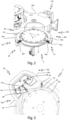
- Figure 2 shows an excerpt from Fig. 1 illustrated embodiment of the container treatment device 1 in a perspective view obliquely from above.
- the transport device 4 can be seen in the foreground.
- the heating device 2 located downstream in this respect is not shown.
- the transport device 4 has a plurality of holding elements 40 for receiving the containers 10, of which one holding element 40e is arranged in the region of the inlet 60 of the radiation shielding device 50 and another holding element 40a is arranged in the region of the outlet 70 of the radiation shielding device 50.
- a container 10 is not arranged in either of these two holding elements 40a and 40e, but in normal operation the holding element 40e arranged in the region of the inlet 60 of the radiation shielding device 50 would be equipped with a container 10.
- the radiation shielding device 50 is designed in the section 50e between the inlet 60 and the transfer area 90, which is located in the area of the opening 420 in the housing 400, in such a way that a container can be guided therein.
- the radiation shielding device 50 has a channel 56 in the section 50e, which extends along a section of the transport path T and in which the containers can be guided along the transport path T.
- the channel formed by the radiation shielding device 50 has a smaller cross-section in this section 50a than in section 50e. However, the channel is also sufficiently wide in section 50a so that the holding elements 40 can be passed through and thus follow the rotation of the rotatable carrier 20.
- the terms holding element and holding device are used synonymously in this description.
- the radiation shielding device 50 is designed in two parts and comprises an upper radiation shielding device part 50o and a lower radiation shielding device part 50u. This multi-part design makes it possible to open the radiation shielding device 50 by moving the two radiation shielding device parts 50o and 50u apart, for example for cleaning or maintenance purposes.
- Figure 3 shows a plan view of the transfer area 90 without the upper part 50o of the radiation shielding device 50.
- the upper radiation shielding device part 50o of the radiation shielding device 50 is removed from the lower radiation shielding device part 50u, so that the area located within the radiation shielding device 50, such as the channel 56, becomes accessible, for example for cleaning or maintenance work.
- the holding elements 40 can also be seen.
- the transfer area 90 can also be seen, which extends into an opening 420 in the housing wall.
- the containers 10 are transferred from a holding element 40 of the first transport device 4 to a holding device 140 of the second transport device 100.
- the transfer area 90 preferably also represents a clean room boundary. Areas that lie outside the housing 400 are usually not sterilized. The penetration of contamination into the clean room can be prevented, for example, by an overpressure inside the housing 400. This overpressure results in a continuous gas flow from the inside of the housing 400 through the opening 420 to the outside, so that contamination against this gas flow is only possible to a very limited extent.
- the containers 10 introduced into the clean room in the transfer area 90 are not sterile, but immediately after introduction they are brought by the second transport device into the effective range of the radiation source 150 (not shown here) and sterilized there. The containers only come into contact beforehand with the associated holding device 140, which is also guided past the radiation source 150 and is also sterilized. The risk of contamination is therefore extremely low.
- Control curves 70, 80 can be seen, by means of which the holding elements 40 can be controlled relative to the rotatable carrier 20.
- guide rollers 82, 86 are each arranged on a control curve 80, 84. These guide rollers 82, 86 roll on the respective control curve 80, 84 when the rotatable carrier rotates and move a mechanism connected to the guide rollers 82, 86 in accordance with the radial distance of the guide roller 82, 86 from the axis of rotation.
- This allows movements of the holding elements 40 to be controlled depending on the sector that this holding element 40 is currently sweeping over during rotation. This makes it possible for each holding element 40 to make exactly one predetermined movement at a certain position on the circular path.
- This movement can also be a combination of several movements that are predetermined by different control curves 80, 84.
- a first control curve 70 could control a movement of the holding element 40 in the radial direction
- another control curve specifies a relative movement of the holding element 40 with respect to the rotatable carrier 20 along the circumferential direction.
- the opening and closing of a holding device 40 for holding a container or a lifting movement of the holding device 40 along the longitudinal direction of the container could be controlled by a guide curve.
- control curve 80 is shaped such that a holding element 40 is displaced radially inwards both before and after reaching the transfer area 90.
- the holding element 40 is only displaced radially outwards immediately before and after the arrangement of the holding element 40 in the transfer area 90. Due to this design, the path covered by the holding element 40 before and after the transfer area 90 changes the radius of curvature several times.
- the change in the radius of curvature can include a change from a strong radius of curvature to a small radius of curvature (with the same sign and thus the same direction of curvature) and vice versa.
- the radius of curvature changes the sign (i.e. the direction of curvature) at least once.
- the channel 56 preferably follows this curvature and has a corresponding change in its radius of curvature.
- the radiation shielding device 50 can still effectively prevent radiation incident along the course of the channel from escaping into the environment, since particularly effective reflection and/or absorption of the radiation occurs in areas with a particularly strong radius of curvature.
- the radiation shielding device 50 forms a radiation trap by changing the radius of curvature and/or the direction of curvature (if necessary several times).
- the radiation is preferably reflected and/or absorbed several times in this area, so that the intensity of the radiation is weakened and/or the radiation is reflected back into the interior of the housing.
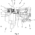
- Figure 4 shows a sectional view of the container treatment device 1 in the area of the container transfer 90.
- a section of the first transport device 4 is shown on the left.
- An arm 30 is shown to which a holding element 40 is attached. This arm 30 can be moved relative to the rotatable carrier 20 via the guide rollers 82 and 86 rolling on the control curves 80 and 84. For example, it is possible to push the holding device 40 in the area of the opening 420 in the housing wall 400 radially outwards in the direction of a holding device 140 of the second transport device 100.
- a container 10 is shown which is contacted by two holding devices 40, 140.
- This container 10 is therefore currently being transferred from the holding device 40 of the first transport device 4 to a holding device 140 of the second transport device 100.
- the holding device 40 of the first transport device 4 can release the container and, for example, retract it radially inwards with respect to the rotatable carrier 20. This can be done, for example, by means of one of the control cams 80, 84.
- the container can then be moved further on the holding device 140 of the second transport device 100, for example by rotating the rotatable carrier 120 on which the holding device 140 is arranged.
- At least one holding device 140 of the container outer surface treatment device 100 can be brought into the area of an opening 420 of the housing wall 400, at least temporarily. This makes it possible for this holding element 140 to receive a container from a space 412 outside the housing 400 from a transport device 4 arranged there upstream with respect to the transport path. This design makes it possible to dispense with an additional transport device within the housing, which receives the container from outside and forwards it to the container outer surface treatment device 100.
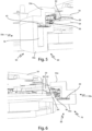
- Figure 5 shows a sectional view of the inlet 60 into the radiation shielding device 50.
- the inlet 60 is followed along the transport path T by the section 50e of the radiation shielding device 50 between the inlet 60 and the transfer area 90.
- the radiation shielding device 50 is designed in at least two parts and comprises an upper radiation shielding device part 50o and a lower radiation shielding device part 50u. Together, these radiation shielding device parts 50u and 50o form a casing of the transport path, which encloses it in a vertical cross-sectional direction so that radiation cannot escape directly. If radiation could escape at all, this would only be possible after repeated reflection on the inner surfaces of the radiation shielding device 50 and the associated energy loss.
- the holding device 40 can thus be connected to the rotatable carrier via an arm 30 and the container 10 (not shown) can still be guided inside the channel 56 formed by the radiation shielding device 50.
- control cams 80 and 84 are clearly visible, which can control the holding element 40 by interacting with the guide rollers 82 and 86, respectively.
- Figure 6 shows a sectional view of the outlet 70 from the radiation shielding device 50.
- the outlet 70 closes off the section 50a of the radiation shielding device 50 along the transport path T, which is arranged between the transfer area 90 and the outlet 70.
- the radiation shielding device 50 is preferably also designed in at least two parts and comprises an upper radiation shielding device part 50o and a lower radiation shielding device part 50u.
- no containers are usually guided through the radiation shielding device 50, so the formation of a comparatively large channel is not necessary. Rather, the area between the upper radiation shielding device part 50o and the lower radiation shielding device part 50u can be so narrow that only the holding device 40 can be guided through between these two radiation shielding device parts 50o and 50u.
- the small space between the two radiation shielding device parts 50u and 50o prevents the escape of radiation particularly well. If radiation could escape at all, this would only be possible after repeated reflection on the inner surfaces of the radiation shielding device 50 and the associated energy loss. The number of reflections and thus also the energy loss is significantly increased due to the significantly smaller free distance between the inner walls of the radiation shielding device 50 compared to section 50e. The escape of high-energy radiation can thus be effectively prevented.
- control cams 80 and 84 are clearly visible, which can control the holding element 40 by interacting with the guide rollers 82 and 86, respectively.
- Figure 7 shows a schematic oblique view of a container treatment device 1 with upstream and downstream container treatment devices 2, 500.
- the container treatment devices 2, 500 shown in the example shown are, on the one hand, a heating device 2 which is arranged upstream of the first transport device 4 and, on the other hand, a container forming device 500.
- a heating device 2 which is arranged upstream of the first transport device 4
- a container forming device 500 In the container forming device 500, for example, preforms are formed into bottles, preferably blow-molded.
- An inlet star 490 is connected upstream of the container forming device 500 and an outlet star 510 is connected downstream.
- the container treatment device 1 is a sterilization device in which the containers are exposed to sterilizing radiation from the radiation source 150. Likewise, the container treatment device 1 provides for internal container sterilization in the area of the transport device 300. However, at least some of the devices required for this are in Figure 7 not shown.
- the radiation shielding device 50 is in Figure 7 shown in a closed state.
- the upper radiation shielding device part 50o thus rests on the lower radiation shielding device part 50u, so that a flush barrier for radiation emerging from the transfer area exists.
- an opening 58 is provided through which a fluid can be fed into the transfer area 90.
- the opening can therefore also be referred to as a fluid connection.
- a (preferably sterile) fluid By supplying a (preferably sterile) fluid into the transfer area, an overpressure can be generated locally there, which causes the fluid, preferably a gas, to flow out of the housing 400 through the opening 420. This can effectively prevent the inflow of contaminants against this fluid flow. However, this does not significantly hinder the introduction of the containers into the interior of the housing.
- Figure 8 shows a further schematic oblique view of a container treatment device with upstream and downstream container treatment devices in a state with the radiation shielding device 50 open.
- the in Figure 8 The container treatment devices 2, 500 shown upstream and downstream of the container treatment device 1 correspond to the Figure 7 shown. This involves a heating device 2 arranged upstream of the first transport device 4 and a container forming device 500 arranged downstream of the container treatment device 1.
- an inlet star 490 is arranged upstream of the container forming device 500 and an outlet star 510 is arranged downstream.
- the container treatment device 1 is in turn a sterilization device, with an external container sterilization by the radiation source 150 and an internal container sterilization in the area of the transport device 300.
- the radiation shielding device 50 is in Figure 8 shown in an open state in which the upper radiation shielding device part 50o has been removed upwards from the lower radiation shielding device part 50u. As a result, the space formed between these two radiation shielding device parts 50o and 50u is accessible, for example for cleaning or maintenance work.
- the transfer area is accessible in this state. This makes it relatively easy to maintain this area and/or correctly adjust the transfer of the containers.
- the transfer area has proven to be particularly critical, which is why a particularly precise adjustment of the transfer is necessary, in particular the coordination of the movement of the holding elements 40 of the first transport device 4 and the holding elements 140 of the second transport device 100, if necessary taking into account the geometry of the containers to be transferred.
- the upper radiation shielding device part 50o is formed in at least two parts.
- a part 50d of the upper radiation shielding device part 50o which is preferably at least partially a cover of the opening 420 in the housing 400, is separately movable. This makes it possible for the particularly critical area in the transfer area to be made separately accessible or not. For example, it can be advantageous to leave this area covered if, for example, maintenance is necessary due to a container arranged in section 50a of the radiation shielding device 50 between the transfer area 90 and the outlet 70 that has not been correctly transferred.
- a separate opening of the part 50d of the upper radiation shielding device part 50o can be useful if, for example, maintenance or adjustment is necessary in the area of the transfer 90 and contamination of the channel between the upper and lower radiation shielding device parts 50o and 50u is to be avoided.
Landscapes
- Health & Medical Sciences (AREA)
- Epidemiology (AREA)
- Life Sciences & Earth Sciences (AREA)
- Animal Behavior & Ethology (AREA)
- General Health & Medical Sciences (AREA)
- Public Health (AREA)
- Veterinary Medicine (AREA)
- Engineering & Computer Science (AREA)
- Mechanical Engineering (AREA)
- Specific Conveyance Elements (AREA)
Applications Claiming Priority (1)
| Application Number | Priority Date | Filing Date | Title |
|---|---|---|---|
| DE102023116964.5A DE102023116964A1 (de) | 2023-06-27 | 2023-06-27 | Vorrichtung und Verfahren zum Behandeln und insbesondere Sterilisieren von Behältnissen |
Publications (1)
| Publication Number | Publication Date |
|---|---|
| EP4483911A1 true EP4483911A1 (fr) | 2025-01-01 |
Family
ID=90482592
Family Applications (1)
| Application Number | Title | Priority Date | Filing Date |
|---|---|---|---|
| EP24166940.7A Pending EP4483911A1 (fr) | 2023-06-27 | 2024-03-27 | Dispositif et procédé de traitement et notamment de stérilisation de récipients |
Country Status (4)
| Country | Link |
|---|---|
| US (1) | US20250002266A1 (fr) |
| EP (1) | EP4483911A1 (fr) |
| CN (1) | CN222974253U (fr) |
| DE (1) | DE102023116964A1 (fr) |
Citations (4)
| Publication number | Priority date | Publication date | Assignee | Title |
|---|---|---|---|---|
| DE7523323U (de) * | 1975-07-19 | 1975-11-20 | Bekum Maschinenfabriken Gmbh | Drehvorrichtung zur ausrichtung von behaeltern |
| DE102012110108A1 (de) * | 2012-10-23 | 2014-04-24 | Krones Ag | Vorrichtung zur Außensterilisation von Kunststoffvorformlingen |
| EP2388129B1 (fr) * | 2010-05-20 | 2014-05-07 | Krones AG | Dispositif de déformation d'ébauches en matière synthétique dotées d'un espace stérile |
| EP2845610A1 (fr) | 2013-09-10 | 2015-03-11 | Krones AG | Dispositif pour protection contre les rayonnements de stérilisation de récipients |
Family Cites Families (12)
| Publication number | Priority date | Publication date | Assignee | Title |
|---|---|---|---|---|
| NL9201065A (nl) * | 1992-06-16 | 1994-01-17 | Od & Me Bv | Inrichting voor het bewerken van schijfvormige registratiedragers. |
| JP2000214300A (ja) * | 1999-01-25 | 2000-08-04 | Mitsubishi Heavy Ind Ltd | 電子線殺菌装置 |
| US8513623B2 (en) * | 2006-11-08 | 2013-08-20 | Skan Ag | Installation for sterilizing objects by means of a radiation source |
| ES2340541T3 (es) * | 2007-06-15 | 2010-06-04 | TETRA LAVAL HOLDINGS & FINANCE SA | Unidad de separacion para separar dispositivos de apertura para ser aplicados individualmente a respectivos envases de productos alimenticios vertibles. |
| JP5256766B2 (ja) * | 2008-02-18 | 2013-08-07 | 澁谷工業株式会社 | 物品処理装置 |
| US8418836B2 (en) * | 2010-05-07 | 2013-04-16 | The Procter & Gamble Company | Universally adjustable star wheel |
| DE102010020724A1 (de) * | 2010-05-17 | 2011-11-17 | Krones Ag | Rotierende Vorrichtung zum Transport von Artikeln |
| WO2012107172A1 (fr) * | 2011-02-10 | 2012-08-16 | Khs Gmbh | Machine de traitement de récipients à étoiles de transport mobiles |
| JP6080918B2 (ja) * | 2015-07-30 | 2017-02-15 | 日立造船株式会社 | 電子線殺菌設備及び電子線殺菌方法 |
| DE102017101745A1 (de) * | 2017-01-30 | 2018-08-02 | Krones Ag | Vorrichtung und Verfahren zum Sterilisieren von Kunststoffvorformlingen mit vorangegangener Prüfung der Kunststoffvorformlinge |
| DE202017105447U1 (de) * | 2017-09-08 | 2018-12-18 | Krones Aktiengesellschaft | Behälterbehandlungsanlage |
| DE102021134541A1 (de) * | 2021-12-23 | 2023-06-29 | Krones Aktiengesellschaft | Vorrichtung und Verfahren zum Behandeln und insbesondere Sterilisieren von Behältnissen |
-
2023
- 2023-06-27 DE DE102023116964.5A patent/DE102023116964A1/de active Pending
-
2024
- 2024-03-27 EP EP24166940.7A patent/EP4483911A1/fr active Pending
- 2024-06-26 CN CN202421484323.8U patent/CN222974253U/zh active Active
- 2024-06-27 US US18/757,126 patent/US20250002266A1/en active Pending
Patent Citations (4)
| Publication number | Priority date | Publication date | Assignee | Title |
|---|---|---|---|---|
| DE7523323U (de) * | 1975-07-19 | 1975-11-20 | Bekum Maschinenfabriken Gmbh | Drehvorrichtung zur ausrichtung von behaeltern |
| EP2388129B1 (fr) * | 2010-05-20 | 2014-05-07 | Krones AG | Dispositif de déformation d'ébauches en matière synthétique dotées d'un espace stérile |
| DE102012110108A1 (de) * | 2012-10-23 | 2014-04-24 | Krones Ag | Vorrichtung zur Außensterilisation von Kunststoffvorformlingen |
| EP2845610A1 (fr) | 2013-09-10 | 2015-03-11 | Krones AG | Dispositif pour protection contre les rayonnements de stérilisation de récipients |
Also Published As
| Publication number | Publication date |
|---|---|
| US20250002266A1 (en) | 2025-01-02 |
| CN222974253U (zh) | 2025-06-13 |
| DE102023116964A1 (de) | 2025-01-02 |
Similar Documents
| Publication | Publication Date | Title |
|---|---|---|
| EP2724731B1 (fr) | Dispositif de stérilisation extérieure des conteneurs plastiques | |
| EP2594493B1 (fr) | Dispositif de stérilisation intérieure et extérieure de préforms au moyen du rayonnement d'un support de chargement et méthod et ligne de traitement correspondant | |
| EP2371397B1 (fr) | Dispositif de stérilisation de récipients | |
| EP2604410B1 (fr) | Dispositif de déformation d'ébauches en plastique, installation de remplissage de boissons et procédé | |
| EP2594495B2 (fr) | Dispositif, système et méthode avec elément de support à accroche intérieure pour la stérilisation de récipients au moyens de faisceaux d'électrons | |
| EP2848263B1 (fr) | Dispositif de stérilisation des parisons de plastique à la stérilisation intérieure et externe simultanée | |
| EP2731631B1 (fr) | Procédé et dispositif de production de récipients pour boissons remplis de liquides | |
| EP2650022B1 (fr) | Dispositif et procédé destinés à la stérilisation à base de rayonnement de fermetures de récipients | |
| EP2431058B1 (fr) | Unité de stérilisation aseptisée pour une salle blanche | |
| EP2491955A1 (fr) | Procédé et dispositif destinés à la stérilisation de récipients | |
| EP2684673A1 (fr) | Dispositif de chauffage dýébauches en matière synthétique dotées dýun espace stérile et le procédé | |
| EP4227232A2 (fr) | Dispositif et procédé de traitement et notamment de stérilisation de récipients | |
| DE202013104114U1 (de) | Vorrichtung zur Strahlenabschirmung beim Sterilisieren von Behältnissen | |
| EP2559444B1 (fr) | Procédé et dispositif de stérilisation de récipients en plastique avec dispositif de protection | |
| EP4201432A2 (fr) | Dispositif et procédé de traitement et notamment de stérilisation de récipients | |
| DE102007029567A1 (de) | Sterilisation mit β-Strahlung | |
| EP4272767A1 (fr) | Dispositif et procédé de stérilisation de récipients | |
| DE102021134541A1 (de) | Vorrichtung und Verfahren zum Behandeln und insbesondere Sterilisieren von Behältnissen | |
| EP2594492B1 (fr) | Dispositif de stérilisation d'un récipient, installation de remplissage de boissons et/ou installation de fabrication de récipients de boissons ainsi que le procédé de stérilisation d'un récipient contenant des volumes limités par une paroi intérieure | |
| EP3733217B1 (fr) | Dispositif et procédé de stérilisation de fermetures de récipient | |
| DE102023116964A1 (de) | Vorrichtung und Verfahren zum Behandeln und insbesondere Sterilisieren von Behältnissen | |
| EP2842579B1 (fr) | Procédé et dispositif de stérilisation de récipients avec un dispositif de nettoyage d'une fenêtre de rayon | |
| EP4209231A1 (fr) | Dispositif et procédé de traitement et notamment de stérilisation de récipients | |
| EP4201433A1 (fr) | Dispositif et procédé de traitement et notamment de stérilisation de récipients | |
| EP2803368B1 (fr) | Dispositif et procédé destinés à la stérilisation de récipients dotés de dispositif de blindage contre les rayons X |
Legal Events
| Date | Code | Title | Description |
|---|---|---|---|
| PUAI | Public reference made under article 153(3) epc to a published international application that has entered the european phase |
Free format text: ORIGINAL CODE: 0009012 |
|
| STAA | Information on the status of an ep patent application or granted ep patent |
Free format text: STATUS: THE APPLICATION HAS BEEN PUBLISHED |
|
| AK | Designated contracting states |
Kind code of ref document: A1 Designated state(s): AL AT BE BG CH CY CZ DE DK EE ES FI FR GB GR HR HU IE IS IT LI LT LU LV MC ME MK MT NL NO PL PT RO RS SE SI SK SM TR |
|
| STAA | Information on the status of an ep patent application or granted ep patent |
Free format text: STATUS: REQUEST FOR EXAMINATION WAS MADE |
|
| 17P | Request for examination filed |
Effective date: 20250630 |
|
| STAA | Information on the status of an ep patent application or granted ep patent |
Free format text: STATUS: EXAMINATION IS IN PROGRESS |
|
| 17Q | First examination report despatched |
Effective date: 20251031 |