EP4483982A1 - Filtervorrichtung, insbesondere für einen kühlkreislauf - Google Patents
Filtervorrichtung, insbesondere für einen kühlkreislauf Download PDFInfo
- Publication number
- EP4483982A1 EP4483982A1 EP24184481.0A EP24184481A EP4483982A1 EP 4483982 A1 EP4483982 A1 EP 4483982A1 EP 24184481 A EP24184481 A EP 24184481A EP 4483982 A1 EP4483982 A1 EP 4483982A1
- Authority
- EP
- European Patent Office
- Prior art keywords
- filter
- longitudinal
- filtration device
- connector
- longitudinal axis
- Prior art date
- Legal status (The legal status is an assumption and is not a legal conclusion. Google has not performed a legal analysis and makes no representation as to the accuracy of the status listed.)
- Pending
Links
Images


Classifications
-
- B—PERFORMING OPERATIONS; TRANSPORTING
- B01—PHYSICAL OR CHEMICAL PROCESSES OR APPARATUS IN GENERAL
- B01D—SEPARATION
- B01D29/00—Filters with filtering elements stationary during filtration, e.g. pressure or suction filters, not covered by groups B01D24/00 - B01D27/00; Filtering elements therefor
- B01D29/11—Filters with filtering elements stationary during filtration, e.g. pressure or suction filters, not covered by groups B01D24/00 - B01D27/00; Filtering elements therefor with bag, cage, hose, tube, sleeve or like filtering elements
- B01D29/13—Supported filter elements
- B01D29/23—Supported filter elements arranged for outward flow filtration
-
- F—MECHANICAL ENGINEERING; LIGHTING; HEATING; WEAPONS; BLASTING
- F01—MACHINES OR ENGINES IN GENERAL; ENGINE PLANTS IN GENERAL; STEAM ENGINES
- F01P—COOLING OF MACHINES OR ENGINES IN GENERAL; COOLING OF INTERNAL-COMBUSTION ENGINES
- F01P11/00—Component parts, details, or accessories not provided for in, or of interest apart from, groups F01P1/00 - F01P9/00
- F01P11/06—Cleaning; Combating corrosion
-
- B—PERFORMING OPERATIONS; TRANSPORTING
- B01—PHYSICAL OR CHEMICAL PROCESSES OR APPARATUS IN GENERAL
- B01D—SEPARATION
- B01D35/00—Filtering devices having features not specifically covered by groups B01D24/00 - B01D33/00, or for applications not specifically covered by groups B01D24/00 - B01D33/00; Auxiliary devices for filtration; Filter housing constructions
- B01D35/02—Filters adapted for location in special places, e.g. pipe-lines, pumps, stop-cocks
-
- H—ELECTRICITY
- H01—ELECTRIC ELEMENTS
- H01M—PROCESSES OR MEANS, e.g. BATTERIES, FOR THE DIRECT CONVERSION OF CHEMICAL ENERGY INTO ELECTRICAL ENERGY
- H01M8/00—Fuel cells; Manufacture thereof
- H01M8/04—Auxiliary arrangements, e.g. for control of pressure or for circulation of fluids
- H01M8/04007—Auxiliary arrangements, e.g. for control of pressure or for circulation of fluids related to heat exchange
- H01M8/04044—Purification of heat exchange media
-
- B—PERFORMING OPERATIONS; TRANSPORTING
- B01—PHYSICAL OR CHEMICAL PROCESSES OR APPARATUS IN GENERAL
- B01D—SEPARATION
- B01D2201/00—Details relating to filtering apparatus
- B01D2201/02—Filtering elements having a conical form
-
- B—PERFORMING OPERATIONS; TRANSPORTING
- B01—PHYSICAL OR CHEMICAL PROCESSES OR APPARATUS IN GENERAL
- B01D—SEPARATION
- B01D2201/00—Details relating to filtering apparatus
- B01D2201/04—Supports for the filtering elements
- B01D2201/0415—Details of supporting structures
- B01D2201/0423—Details of supporting structures not in the inner side of the cylindrical filtering elements
-
- F—MECHANICAL ENGINEERING; LIGHTING; HEATING; WEAPONS; BLASTING
- F01—MACHINES OR ENGINES IN GENERAL; ENGINE PLANTS IN GENERAL; STEAM ENGINES
- F01P—COOLING OF MACHINES OR ENGINES IN GENERAL; COOLING OF INTERNAL-COMBUSTION ENGINES
- F01P11/00—Component parts, details, or accessories not provided for in, or of interest apart from, groups F01P1/00 - F01P9/00
- F01P11/04—Arrangements of liquid pipes or hoses
-
- F—MECHANICAL ENGINEERING; LIGHTING; HEATING; WEAPONS; BLASTING
- F01—MACHINES OR ENGINES IN GENERAL; ENGINE PLANTS IN GENERAL; STEAM ENGINES
- F01P—COOLING OF MACHINES OR ENGINES IN GENERAL; COOLING OF INTERNAL-COMBUSTION ENGINES
- F01P11/00—Component parts, details, or accessories not provided for in, or of interest apart from, groups F01P1/00 - F01P9/00
- F01P11/06—Cleaning; Combating corrosion
- F01P2011/061—Cleaning or combating corrosion using filters
Definitions
- the invention relates to the field of filtration devices, in particular for cooling circuits.
- Motor vehicle engines for example, are equipped with a cooling circuit that is necessary for their proper functioning.
- the cooling circuit keeps the engine at a lower operating temperature than the recommended maximum temperature and prevents the engine from overheating.
- an engine cooling system typically includes pipes for circulating a coolant from a coolant source to the engine. Over the life of the engine, particles can accumulate in the pipes until they clog them and prevent the coolant from passing through. The accumulation of these particles can cause irreversible damage to the engine or to the components of the cooling system.
- particulate filters In order to prevent the accumulation of these particles, it has been proposed to equip the cooling circuits with filtration devices comprising particulate filters.
- the proposed particulate filters are bulky and their integration into the engines is not easy.
- the storage and transport of particulate filters are particularly restrictive and the manufacturing process of such filters is complex.
- the document US-A1 -2020/0054973 describes a filtration device for a cooling circuit of a fuel cell engine.
- the filtration device comprises a tubular connector having at least one coolant inlet and at least one coolant outlet, and a particulate filter mounted in the connector and extending into the connector from the connector inlet.
- the filter has a generally elongated shape and has a first open longitudinal end located on the inlet side and a second closed longitudinal end located inside the connector.
- the filter includes a filter cloth extending around and along a longitudinal axis of the filter, and a body overmolded on the cloth.
- the particle filter is fixed to the fitting by welding.
- Such a filter fixing system has disadvantages. Indeed, the welding process is long, expensive and complex. In addition, it constitutes an irreversible means of fixing. In the event of wear of the filter cloth for example or in the event of clogging by accumulation of particles in the filter, it is necessary to dismantle the entire filtration device, that is to say to remove the fitting from the cooling circuit and to replace it with a new assembly formed by a fitting and a filter.
- the second end of the filter has a funnel that allows particles to be collected and discharged.
- Such a funnel configuration of the second end of the filter causes disturbances in the flow of the coolant and therefore pressure losses in the cooling circuit that can be detrimental to engine performance.
- the filtration device is remarkable in that the filter is removably mounted in said connector and in that said second end has a bottom wall which converges towards the longitudinal axis and towards said first longitudinal end.
- the filter is mounted in the connector in a removable manner.
- a removable connection makes it easier to mount and dismount the filter in the connector. The installation of the filtration device as well as its maintenance are facilitated.
- the bottom wall of the second end of the filter converges towards the longitudinal axis and towards the first end as opposed to the funnel configuration of the prior art.
- Such a feature of the invention makes it possible to guide the cooling fluid flowing in the filter towards the filter cloth and thus to promote its flow in the cooling circuit, downstream of the filtration device.
- the bottom wall according to the invention makes it possible to reduce flow disturbances in the connection and thus to reduce pressure losses in the cooling circuit.
- the filtration device of the invention it is therefore possible to easily mount and dismount the filter, and guarantee the flow of the cooling fluid in the cooling circuit without significant pressure losses.
- the invention also relates to a cooling circuit for an engine.
- the cooling circuit is remarkable in that it comprises at least one filtration device according to any one of the preceding characteristics.
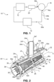
- FIG. 1 illustrates for example a cooling circuit 10 for an engine 12, in particular of a motor vehicle.
- the cooling circuit 10 could however be according to the invention the cooling circuit of a fuel cell.
- the cooling circuit 10 comprises for example a source 14 of cooling fluid, a pump 16 arranged between the source 14 and the engine 12.
- the pump 16 comprises a cooling fluid inlet port 16a connected to the source 14 and a cooling fluid outlet port 16b.
- the cooling circuit 10 further comprises at least one pipe 18 for the passage of the cooling fluid from the source 14 to the engine 12.
- the pipe 18 is for example formed of a plurality of conduits 20a, 20b connected to each other.
- the engine 12 is for example thermal, electric or hydrogen, for example of the fuel cell type.
- the coolant is for example a liquid, in particular water.
- the cooling circuit 10 further comprises a filtration device 22.
- the filtration device 22 is in particular mounted between the pump 16 and the motor 12, in particular between the outlet port 16b of the pump 16 and the motor 12.
- the filtration device 22 comprises a connection 24 and a particle filter 26 mounted in the connection 24.
- connection 24 is tubular and has a longitudinal axis X.
- upstream and downstream are understood relative to the direction of flow F of the cooling fluid in the filtration device 22 along the longitudinal axis X.
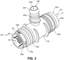
- the connector 24 has a tubular body extending longitudinally between first and second longitudinal ends 24a, 24b. It further comprises a first internal passage 28 extending longitudinally between the longitudinal ends 24a, 24b.
- the connection 24 comprises at least one inlet 30 for cooling fluid and one outlet 32 for this cooling fluid.
- the inlet 30 is for example connected to the outlet 16b of the pump 16 and the outlet 32 is connected to the motor 12.
- the inlets and outlets 30, 32 are for example respectively arranged at level of the first and second longitudinal ends 24a, 24b.
- the inlet and outlet 30, 32 each have an annular edge 30a, 32a.
- the connector 24 is for example T-shaped.
- the tubular body comprises a first tube 24c extending longitudinally from the first end 24a, a second tube 24d extending to the second end 24b and being coaxial with the first tube 24c.
- the tubular body comprises a third intermediate tube 24e which extends perpendicular to the longitudinal axis X of the first and second tubes 24c, 24d.
- the third tube 24e has an auxiliary passage 24e' for the cooling fluid which opens into the first internal passage 28.
- the third tube 24e also has an external radial end 24f on which a second outlet 24f' for the cooling fluid is provided.
- the first, second and third tubes 24c, 24d, 24e each have an internal diameter, the internal diameter of the first and second tubes 24c, 24d being advantageously identical and greater than the internal diameter of the third tube 24e.
- the internal diameter of the first and second tubes 24c, 24d is for example 1.5 to four times larger than the internal diameter of the third tube 24e, in particular twice as large as the internal diameter of the third tube 24e.
- the connector 24 further has at least one slot 34, and advantageously a plurality of slots 34.
- the slots 34 are provided in the first end 24a of the connector 24.
- the slots 34 are regularly distributed around the longitudinal axis X. Their number is for example between three and ten, and may be greater than ten.
- Each slot 34 has for example a polygonal shape, for example square or rectangular.
- the connector 24 is mounted in the cooling circuit 10, for example by force fitting into the conduits 20a, 20b.
- the connector 24 comprises, for example, external annular grooves 25. formed for example on the first, second and third pipes 24c, 24d, 24e.
- the filter 26 is a particle filter mounted in the connector 24.
- the filter 26 has a generally elongated shape centered on the longitudinal axis X.
- the filter 26 has a length l as measured along the longitudinal axis X greater than or equal to 80% of the length L of the connector 24.
- the filter 26 is located in the first passage 28.
- the filter 26 further has a second internal passage 35 for the circulation of the cooling fluid.
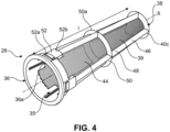
- the filter 26 extends along the longitudinal axis X between a first open longitudinal end 36 and a second closed longitudinal end 38 and connected together for example by a truncated filter wall 39 centered on the longitudinal axis X.
- the first and second longitudinal ends 36, 38 are annular and centered on the longitudinal axis X. They respectively have a first and second internal diameter.
- the first internal diameter of the first longitudinal end 36 of the filter 26 is greater than the second internal diameter of the second longitudinal end 38.
- the first diameter is 1.5 times to four times larger, in particular twice as large as the second internal diameter of the second longitudinal end 38.
- the first longitudinal end 36 is located on the side of the inlet 30 of the connector 24.
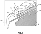
- the first longitudinal end 36 has an external annular shoulder or a lip 36a which is in axial support against the annular edge 30a of the inlet 30 of the connector 24.
- the external diameter of the external annular shoulder 36a is equal to the external diameter of the annular edge 30a of the inlet 30 of the connector 24.
- the external annular shoulder 36a is thus axially aligned with the annular edge 30a of the inlet 30 of the connector 24.
- the second longitudinal end 38 is located inside the connector 24, and preferably downstream of the third tube 24e.
- the second longitudinal end 38 is closed by a bottom wall 40.
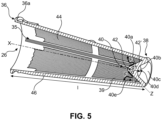
- the bottom wall 40 has an upstream surface 40a located inside the filter 26 and a downstream surface 40b perpendicular to the longitudinal axis X and located outside the second internal passage 35.
- the bottom wall 40 converges towards the longitudinal axis X and towards the first longitudinal end 36 of the filter 26.
- the upstream surface 40a is therefore conical or frustoconical and has a peak 42 centered on the longitudinal axis X and located inside the filter 26, in the internal passage 35 and a base 42' opposite the peak.
- the upstream surface 40 is conical.
- the summit 42 is pointed.
- the axial length of the conical or truncated upstream surface 40 of the bottom wall 40 is at least equal to the diameter of the base of this surface.
- the bottom wall 40 has a thickness as measured along the variable longitudinal axis X. This thickness is maximum at the longitudinal axis X of the filter 26 and decreases towards the periphery of the bottom wall 40.
- the bottom wall 40 has a maximum longitudinal dimension d1 as measured along the longitudinal axis X which represents between 2% and 20%, preferably between 5% and 10% of the length l of the filter 26.
- This longitudinal dimension d1 is measured along the longitudinal axis X between the apex 42 and the downstream surface 40b. It thus represents the maximum thickness of the bottom wall 40. This maximum thickness is at least 1.5 times greater than the minimum thickness of the bottom wall 40 measured at its periphery.
- the conical upstream surface 40a has a generator Z forming an angle ⁇ with the longitudinal axis X of between 10° and 45°.
- the angle ⁇ represents the half angle at the apex of the cone.
- the bottom wall 40 is advantageously made of a polymer material chosen for example from polyamides. It is for example overmolded.
- Such a conical or truncated upstream surface 40a makes it possible to guide the flow of cooling fluid F towards the filtration wall 39 as illustrated by the arrows on the figure 5 .
- Such flow guidance makes it possible to reduce disturbances of the cooling flow in the cooling circuit 10.
- the pressure losses in the cooling circuit are therefore limited.
- the conical upstream surface 40a having a pointed apex 42 makes it possible to further improve the guidance of the cooling flow F towards the filtration wall 39.
- the advantageous length of the conical or truncated upstream surface 40a makes it possible to create a larger guide surface to further improve the guiding of the cooling flow F towards the filtration wall 39.
- the bottom wall 40 is connected to the filtration wall 39 by an annular rim 40c located at the second end 38 of the filter 26.
- the bottom wall 40 and the filtration wall 39 form an angle ⁇ of between 5° and 45°, the angle ⁇ being measured in a plane passing through the longitudinal axis X.
- the annular rim 40c is made of a polymer material identical to the material of the bottom wall 40.
- the annular rim 40 is for example overmolded with the bottom wall 40.
- the bottom wall 40 further has a hollow 40d, also called a cavity, located outside the internal passage 35.
- This hollow 40d has a truncated surface having an upstream end and a downstream end having a diameter greater than the diameter of the upstream end.
- the upstream end of smaller diameter is connected or formed by the downstream surface 40b of the bottom wall 40 while the downstream end of larger diameter is delimited radially by the annular rim 40c.
- the hollow 40d has at least one injection point of a polymer material.
- Such a hollow 40d facilitates the manufacture of the filter 26 by molding. Indeed, the hollow 40d constitutes a zone at the level of which an injection point can be provided. of the polymeric material during the implementation of the molding process.
- the bottom wall 40 advantageously does not have any projecting part which could harm the safety of the operators during the handling and assembly of the filter 26. Furthermore, during the injection of the polymeric material, the maximum axial thickness of the bottom wall 40 promotes the uniform distribution of the material in the mold and limits molding defects.
- the hollow 40d makes it possible to reduce the size of the filter 26. Indeed, with an equal filtration surface, the axial dimension of the filter 26 is reduced thanks to the hollow 40d compared to a bottom wall 40 devoid of such a hollow 40d.
- the filter 26 comprises a storage space 40e for the particles delimited by the base 42' of the upstream surface 40a of the bottom wall 40 and radially by the filtration wall 39.
- the storage space 40e allows the accumulation and storage of the particles in the downstream part of the filter 26 without reducing the useful filtration surface of the filter 26.
- the filtration wall 39 has a substantially truncated cone shape.
- the filtration wall 39 advantageously has an internal diameter which decreases towards the outlet 28 of the connector 24.
- the filter 26 comprises a filter cloth 44 and an overmolded body 46.
- the filter cloth 44 constitutes the filtration wall 39. It thus extends between the first and second longitudinal ends 36, 38. In particular, the filter cloth 44 extends from the annular shoulder 36a to the annular rim 40c.
- the filter cloth 44 has filtration pores for the passage of the cooling fluid while retaining contaminating particles.
- the pores have for example a size of the order of a micrometer, for example between 10 ⁇ m and 500 ⁇ m.
- the filter cloth 44 advantageously has a filtration surface of between 60% and 95% of the total external surface of the filter 26, in particular between 70% and 80% of the total external surface of the filter 26.
- the filter cloth 44 comprises a textile, preferably woven, comprising polymer threads.
- the polymer of the threads is for example chosen from polyamides, polyolefins such as polypropylene, polyethylene or even polyesters.
- the wires preferably have an average diameter of between 100 ⁇ m and 2000 ⁇ m.
- the textile of the filter cloth 44 is free of fillers comprising fibers.
- the body 46 is overmolded onto the filter cloth 44.
- the maintenance of the filter cloth 44 is improved thanks to the conical or truncated upstream surface 40a.
- the body 46 comprises longitudinal ribs 48 and advantageously annular ribs 50 connected to the longitudinal ribs 50.
- the longitudinal ribs 48 and the annular ribs 50 are, according to this first embodiment, overmolded onto the filter cloth 44.
- the longitudinal ribs 48 are regularly distributed around the longitudinal axis X.
- they further extend from the first longitudinal end 36 to the second longitudinal end 38 of the filter 26.
- the longitudinal ribs 48 are preferably located exclusively outside the filter cloth 44 in order to absorb the forces linked to the internal pressure.
- the longitudinal ribs 48 are for example two, three, four or five or more in number depending on the diameter of the filter 26.
- the annular ribs 50 are centered on the longitudinal axis X. They are regularly distributed along the longitudinal axis X.
- the body 46 has for example a first annular rib located on the first longitudinal end 36 and forming the annular shoulder 36a, a second annular rib located on the second longitudinal end 38 and forming the annular rim 40c and according to this embodiment a third central annular rib 50a located at an equal distance from the first and second annular ribs.
- the bottom wall 40 advantageously forms an integral part of the body 46.
- the body 46 comprises a polymer material, preferably identical to the polymer material of the filter cloth 44.
- the polymer material is chosen from polyamides.
- the body 46 is for example formed by overmolding.
- the body 46 makes it possible to reinforce the filter cloth 44 against the forces linked in particular to the internal pressure of the cooling circuit 10.
- the filter 26 is mounted in the connector 24 in a removable manner and preferably by clipping.
- the filter 26 advantageously comprises at least one fixing tab 52 which fits by clipping into a corresponding slot 34 of the connector 24.
- the filter 26 comprises a plurality of tabs 52 regularly distributed around the longitudinal axis X.
- the filter 26 comprises as many tabs 52 as slots 34 and longitudinal ribs 48.
- the tabs 52 are provided on the external periphery of the first longitudinal end 36 of the filter. Preferably, the tabs 52 are axially aligned with the longitudinal ribs 48 or located on the longitudinal ribs 48.
- the tabs 52 are overmolded onto the filter cloth 44. They are for example formed during the manufacture of the body 46 and thus form an integral part of the body 46.
- the tabs 52 have a polygonal shape, preferably substantially rectangular. They each have a lug 52a and a support end 52a allowing the insertion of the lugs 52a into the corresponding slots 34 by pressing the connector 24 on the tabs 52.
- the lugs 52a allow the filter 26 to be blocked in translation and rotation in the connector 24.
- Such a removable connection and preferably by clipping, makes it easier to assemble and disassemble the filter 26 in the connector 24.
- the installation of the filtration device 22 as well as its maintenance are facilitated.
- the conical configuration of the bottom wall 40 makes it possible to guide the coolant towards the filtration wall 39 in order to reduce disturbances in the flow of the coolant in the connector 24 and thus reduce pressure losses in the cooling circuit 10.
- the filtration device 22 of the invention it is therefore possible to easily mount and dismount the filter 26, and guarantee the flow of the cooling fluid in the cooling circuit 10 without significant pressure losses.
- FIG. 7 illustrates a second embodiment of the filter 26.
- the entire description of the Figures 1 to 6 applies to the second embodiment. Only the differences are described below.
- Filter 26 of the figure 7 differs from the filter 26 of the first embodiment described above in that the longitudinal ribs 48 extend discontinuously between the first and second ends 36, 38 of the filter 26.
- each longitudinal rib 48 has a first end 48a connected to an annular rib 50 and a second end 48b connected to another adjacent annular rib 50.
- the longitudinal ribs 48 may be axially aligned or misaligned.
- the longitudinal ribs 48 may be distributed regularly or irregularly about the longitudinal axis X.
- the filter 26 has four annular ribs 50 regularly distributed along the longitudinal axis X, the annular ribs 50 located at the ends respectively forming the external annular shoulder 36a and the annular rim 40c.
- FIG 8 illustrates a third embodiment of the filter 26.
- the entire description of the Figures 1 to 6 applies to the third embodiment. Only the differences are described below.
- Filter 26 of the figure 8 differs from the filter 26 of the first embodiment in that the longitudinal ribs 46 are fixed to the annular ribs 50a and in that a radial space 54 is provided between the filter cloth 44 and each longitudinal rib 46. According to this embodiment, only the annular ribs 50 are overmolded on the filter cloth 44.
- the filter 26 has an inlet 55 for the fluid F located on the side of the first longitudinal end 36 and therefore opposite the bottom wall 40.
- the inlet 55 rests on the connector 24.
- the inlet 55 can be formed by the shoulder or the lip 36a.
- Entrance 55 is annular and centered on the longitudinal axis X.
- the inlet 55 has a general shape that flares out towards the first longitudinal end and towards the outside of the filter 26, therefore moving away from the longitudinal axis X.
- the inlet 55 has a free peripheral edge 56 and an internal surface 57.
- the internal surface 57 has a rounding 58.
- the rounding 58 extends to the peripheral edge 56 of the inlet 55.
- the rounding 58 preferably has a radius of between 2 mm and 10 mm, even more preferably between 3 mm and 5 mm.
- the inlet 55 came in one piece with the body 46 of the filter 26.
- the inlet 55 of the filter 26 having such a rounding 58 makes it possible to limit disturbances of the flow of the fluid. Furthermore, the inlet 55 is formed directly on the body 46 of the filter 26 so that no additional part is necessary to form the inlet of the filter.
Landscapes
- Chemical & Material Sciences (AREA)
- Chemical Kinetics & Catalysis (AREA)
- Engineering & Computer Science (AREA)
- Sustainable Development (AREA)
- Sustainable Energy (AREA)
- Life Sciences & Earth Sciences (AREA)
- Manufacturing & Machinery (AREA)
- Electrochemistry (AREA)
- General Chemical & Material Sciences (AREA)
- Combustion & Propulsion (AREA)
- Mechanical Engineering (AREA)
- General Engineering & Computer Science (AREA)
- Filtering Materials (AREA)
- Lubrication Details And Ventilation Of Internal Combustion Engines (AREA)
Applications Claiming Priority (1)
| Application Number | Priority Date | Filing Date | Title |
|---|---|---|---|
| FR2306989A FR3150445A1 (fr) | 2023-06-30 | 2023-06-30 | Dispositif de filtration, en particulier pour un circuit de refroidissement |
Publications (1)
| Publication Number | Publication Date |
|---|---|
| EP4483982A1 true EP4483982A1 (de) | 2025-01-01 |
Family
ID=88290789
Family Applications (1)
| Application Number | Title | Priority Date | Filing Date |
|---|---|---|---|
| EP24184481.0A Pending EP4483982A1 (de) | 2023-06-30 | 2024-06-25 | Filtervorrichtung, insbesondere für einen kühlkreislauf |
Country Status (4)
| Country | Link |
|---|---|
| US (1) | US20250001331A1 (de) |
| EP (1) | EP4483982A1 (de) |
| CN (1) | CN119222037A (de) |
| FR (1) | FR3150445A1 (de) |
Citations (6)
| Publication number | Priority date | Publication date | Assignee | Title |
|---|---|---|---|---|
| US4207631A (en) * | 1976-04-14 | 1980-06-17 | Gary Baggey | Drain strainer |
| US5820715A (en) * | 1996-02-01 | 1998-10-13 | Standex International Corporation | Method of making flow monitoring line strainer having flow indicating element |
| US20020040569A1 (en) * | 1999-03-24 | 2002-04-11 | Thomas Reinhold | Filter with a cylindrical housing and an annular filter cartridge |
| US20110132817A1 (en) * | 2009-12-03 | 2011-06-09 | Eric Rankin Gardner | Systems and methods associated with straining a pipeline |
| US20200054973A1 (en) | 2018-08-15 | 2020-02-20 | Mann+Hummel Gmbh | Filter element for use as a particulate filter in a cooling circuit of an electrochemical energy converter and arrangement with an electrochemical energy converter and a cooling circuit |
| EP4098345A1 (de) | 2021-05-31 | 2022-12-07 | Robert Bosch GmbH | Filtereinrichtung und brennstoffzellensystem mit filtereinrichtung |
-
2023
- 2023-06-30 FR FR2306989A patent/FR3150445A1/fr active Pending
-
2024
- 2024-06-25 EP EP24184481.0A patent/EP4483982A1/de active Pending
- 2024-06-26 CN CN202410837709.0A patent/CN119222037A/zh active Pending
- 2024-06-28 US US18/758,374 patent/US20250001331A1/en active Pending
Patent Citations (6)
| Publication number | Priority date | Publication date | Assignee | Title |
|---|---|---|---|---|
| US4207631A (en) * | 1976-04-14 | 1980-06-17 | Gary Baggey | Drain strainer |
| US5820715A (en) * | 1996-02-01 | 1998-10-13 | Standex International Corporation | Method of making flow monitoring line strainer having flow indicating element |
| US20020040569A1 (en) * | 1999-03-24 | 2002-04-11 | Thomas Reinhold | Filter with a cylindrical housing and an annular filter cartridge |
| US20110132817A1 (en) * | 2009-12-03 | 2011-06-09 | Eric Rankin Gardner | Systems and methods associated with straining a pipeline |
| US20200054973A1 (en) | 2018-08-15 | 2020-02-20 | Mann+Hummel Gmbh | Filter element for use as a particulate filter in a cooling circuit of an electrochemical energy converter and arrangement with an electrochemical energy converter and a cooling circuit |
| EP4098345A1 (de) | 2021-05-31 | 2022-12-07 | Robert Bosch GmbH | Filtereinrichtung und brennstoffzellensystem mit filtereinrichtung |
Also Published As
| Publication number | Publication date |
|---|---|
| US20250001331A1 (en) | 2025-01-02 |
| FR3150445A1 (fr) | 2025-01-03 |
| CN119222037A (zh) | 2024-12-31 |
Similar Documents
| Publication | Publication Date | Title |
|---|---|---|
| EP1818616B1 (de) | Tubomaschinenbrennkammer mit tangentialen Schlitzen | |
| EP1818614B1 (de) | Ringförmige Brennkammer einer Strömungsmaschine mit abwechselnden Befestigungen | |
| CA2862410C (fr) | Dispositif d'injection d'air et de carburant pour une chambre de combustion d'une turbomachine | |
| EP1818617B1 (de) | Querwand einer Brennkammer, die mit Multiperforationslöchern ausgestattet ist | |
| EP2609372B1 (de) | Brennkammer für einen flugzeugmotor und verfahren zur befestigung eines injektionssystems in einer brennkammer eines flugzeugmotors | |
| FR2935777A1 (fr) | Chambre de combustion de turbomachine | |
| FR2975172A1 (fr) | Dispositif pour le montage d'une bougie d'allumage dans une chambre de combustion de moteur a turbine a gaz | |
| FR2955374A1 (fr) | Chambre de combustion multi-percee a ecoulements tangentiels contre giratoires | |
| EP2088303B1 (de) | Herstellungsverfahren einer Trägerplatte für Drosselkörper und Trägerplatte | |
| FR3058480A1 (fr) | Support assurant une liaison complete entre un arbre turbine et un tube de degazage d'un turboreacteur | |
| FR2952402A1 (fr) | Dispositif de deshuilage d'une enceinte dans une turbomachine | |
| FR3005693A1 (fr) | Turbomachine d'aeronef a double flux comprenant une virole inter-veine a maintien aval simplifie | |
| FR3150445A1 (fr) | Dispositif de filtration, en particulier pour un circuit de refroidissement | |
| WO2025083359A1 (fr) | Dispositif fluidique pour véhicule automobile | |
| FR3121951A1 (fr) | Systeme de renforcement pour un carter de soufflante en materiau composite, carter de soufflante et turbomachine correspondants | |
| FR2987428A1 (fr) | Liaison mecanique amelioree entre un nez d'injecteur et une bague de traversee d'un systeme d'injection pour chambre de combustion de turbomachine | |
| FR3015638A1 (fr) | Segment d'obturation de traversee coulissante de systeme d'injection pour turbomachine | |
| EP3751102B1 (de) | Rotor für den kompressor einer rotationsmaschine und zugehöriges fertigungsverfahren | |
| EP3918204A1 (de) | Lüftergehäuse für eine flugzeugturbomaschine | |
| FR2993347A1 (fr) | Chambre de combustion de turbomachine equipee de passages de debit d'air de purge entre le nez d'injecteur et la bague de traversee du systeme d'injection | |
| FR3037998B1 (fr) | Ensemble pour turbomachine d'aeronef comprenant un carter de turbine ainsi qu'un dispositif de refroidissement par air, et procede d'assemblage d'un tel ensemble | |
| FR3007801A1 (fr) | Element d'injection | |
| FR3105981A1 (fr) | Jonc d’assemblage pour turbomachine | |
| EP3105448B1 (de) | Elastomer verbindung zwischen ein magnetventilrohr und ein ansaugluftrohr aus kunststoff | |
| FR2893389A1 (fr) | Paroi transversale de chambre de combustion munie de trous de multiperforation |
Legal Events
| Date | Code | Title | Description |
|---|---|---|---|
| PUAI | Public reference made under article 153(3) epc to a published international application that has entered the european phase |
Free format text: ORIGINAL CODE: 0009012 |
|
| STAA | Information on the status of an ep patent application or granted ep patent |
Free format text: STATUS: THE APPLICATION HAS BEEN PUBLISHED |
|
| AK | Designated contracting states |
Kind code of ref document: A1 Designated state(s): AL AT BE BG CH CY CZ DE DK EE ES FI FR GB GR HR HU IE IS IT LI LT LU LV MC ME MK MT NL NO PL PT RO RS SE SI SK SM TR |
|
| STAA | Information on the status of an ep patent application or granted ep patent |
Free format text: STATUS: REQUEST FOR EXAMINATION WAS MADE |
|
| 17P | Request for examination filed |
Effective date: 20250620 |
|
| P01 | Opt-out of the competence of the unified patent court (upc) registered |
Free format text: CASE NUMBER: UPC_APP_0006097_4483982/2026 Effective date: 20260219 |