EP4484014A2 - Centrifugeuse et procédé de nettoyage d'une centrifugeuse - Google Patents
Centrifugeuse et procédé de nettoyage d'une centrifugeuse Download PDFInfo
- Publication number
- EP4484014A2 EP4484014A2 EP24213729.7A EP24213729A EP4484014A2 EP 4484014 A2 EP4484014 A2 EP 4484014A2 EP 24213729 A EP24213729 A EP 24213729A EP 4484014 A2 EP4484014 A2 EP 4484014A2
- Authority
- EP
- European Patent Office
- Prior art keywords
- rotor
- cleaning solution
- centrifuge
- rotor chamber
- chamber
- Prior art date
- Legal status (The legal status is an assumption and is not a legal conclusion. Google has not performed a legal analysis and makes no representation as to the accuracy of the status listed.)
- Granted
Links
Images


Classifications
-
- B—PERFORMING OPERATIONS; TRANSPORTING
- B04—CENTRIFUGAL APPARATUS OR MACHINES FOR CARRYING-OUT PHYSICAL OR CHEMICAL PROCESSES
- B04B—CENTRIFUGES
- B04B15/00—Other accessories for centrifuges
- B04B15/06—Other accessories for centrifuges for cleaning bowls, filters, sieves, inserts, or the like
-
- B—PERFORMING OPERATIONS; TRANSPORTING
- B01—PHYSICAL OR CHEMICAL PROCESSES OR APPARATUS IN GENERAL
- B01L—CHEMICAL OR PHYSICAL LABORATORY APPARATUS FOR GENERAL USE
- B01L13/00—Cleaning or rinsing apparatus
- B01L13/02—Cleaning or rinsing apparatus for receptacle or instruments
-
- B—PERFORMING OPERATIONS; TRANSPORTING
- B04—CENTRIFUGAL APPARATUS OR MACHINES FOR CARRYING-OUT PHYSICAL OR CHEMICAL PROCESSES
- B04B—CENTRIFUGES
- B04B11/00—Feeding, charging, or discharging bowls
- B04B11/04—Periodical feeding or discharging; Control arrangements therefor
-
- B—PERFORMING OPERATIONS; TRANSPORTING
- B04—CENTRIFUGAL APPARATUS OR MACHINES FOR CARRYING-OUT PHYSICAL OR CHEMICAL PROCESSES
- B04B—CENTRIFUGES
- B04B13/00—Control arrangements specially designed for centrifuges; Program control of centrifuges
-
- B—PERFORMING OPERATIONS; TRANSPORTING
- B04—CENTRIFUGAL APPARATUS OR MACHINES FOR CARRYING-OUT PHYSICAL OR CHEMICAL PROCESSES
- B04B—CENTRIFUGES
- B04B5/00—Other centrifuges
- B04B5/04—Radial chamber apparatus for separating predominantly liquid mixtures, e.g. butyrometers
- B04B5/0407—Radial chamber apparatus for separating predominantly liquid mixtures, e.g. butyrometers for liquids contained in receptacles
-
- B—PERFORMING OPERATIONS; TRANSPORTING
- B04—CENTRIFUGAL APPARATUS OR MACHINES FOR CARRYING-OUT PHYSICAL OR CHEMICAL PROCESSES
- B04B—CENTRIFUGES
- B04B7/00—Elements of centrifuges
- B04B7/02—Casings; Lids
-
- B—PERFORMING OPERATIONS; TRANSPORTING
- B08—CLEANING
- B08B—CLEANING IN GENERAL; PREVENTION OF FOULING IN GENERAL
- B08B3/00—Cleaning by methods involving the use or presence of liquid or steam
- B08B3/003—Cleaning involving contact with foam
-
- B—PERFORMING OPERATIONS; TRANSPORTING
- B08—CLEANING
- B08B—CLEANING IN GENERAL; PREVENTION OF FOULING IN GENERAL
- B08B3/00—Cleaning by methods involving the use or presence of liquid or steam
- B08B3/04—Cleaning involving contact with liquid
- B08B3/10—Cleaning involving contact with liquid with additional treatment of the liquid or of the object being cleaned, e.g. by heat, by electricity or by vibration
- B08B3/102—Cleaning involving contact with liquid with additional treatment of the liquid or of the object being cleaned, e.g. by heat, by electricity or by vibration with means for agitating the liquid
- B08B3/104—Cleaning involving contact with liquid with additional treatment of the liquid or of the object being cleaned, e.g. by heat, by electricity or by vibration with means for agitating the liquid using propellers
-
- B—PERFORMING OPERATIONS; TRANSPORTING
- B08—CLEANING
- B08B—CLEANING IN GENERAL; PREVENTION OF FOULING IN GENERAL
- B08B9/00—Cleaning hollow articles by methods or apparatus specially adapted thereto
- B08B9/08—Cleaning containers, e.g. tanks
- B08B9/0804—Cleaning containers having tubular shape, e.g. casks, barrels, drums
-
- B—PERFORMING OPERATIONS; TRANSPORTING
- B08—CLEANING
- B08B—CLEANING IN GENERAL; PREVENTION OF FOULING IN GENERAL
- B08B9/00—Cleaning hollow articles by methods or apparatus specially adapted thereto
- B08B9/08—Cleaning containers, e.g. tanks
- B08B9/0821—Handling or manipulating containers, e.g. moving or rotating containers in cleaning devices, conveying to or from cleaning devices
-
- B—PERFORMING OPERATIONS; TRANSPORTING
- B08—CLEANING
- B08B—CLEANING IN GENERAL; PREVENTION OF FOULING IN GENERAL
- B08B9/00—Cleaning hollow articles by methods or apparatus specially adapted thereto
- B08B9/08—Cleaning containers, e.g. tanks
- B08B9/20—Cleaning containers, e.g. tanks by using apparatus into or on to which containers, e.g. bottles, jars, cans are brought
- B08B9/28—Cleaning containers, e.g. tanks by using apparatus into or on to which containers, e.g. bottles, jars, cans are brought the apparatus cleaning by splash, spray, or jet application, with or without soaking
- B08B9/34—Arrangements of conduits or nozzles
-
- B—PERFORMING OPERATIONS; TRANSPORTING
- B08—CLEANING
- B08B—CLEANING IN GENERAL; PREVENTION OF FOULING IN GENERAL
- B08B9/00—Cleaning hollow articles by methods or apparatus specially adapted thereto
- B08B9/08—Cleaning containers, e.g. tanks
- B08B9/20—Cleaning containers, e.g. tanks by using apparatus into or on to which containers, e.g. bottles, jars, cans are brought
- B08B9/42—Cleaning containers, e.g. tanks by using apparatus into or on to which containers, e.g. bottles, jars, cans are brought the apparatus being characterised by means for conveying or carrying containers therethrough
- B08B9/44—Cleaning containers, e.g. tanks by using apparatus into or on to which containers, e.g. bottles, jars, cans are brought the apparatus being characterised by means for conveying or carrying containers therethrough the means being for loading or unloading the apparatus
-
- B—PERFORMING OPERATIONS; TRANSPORTING
- B01—PHYSICAL OR CHEMICAL PROCESSES OR APPARATUS IN GENERAL
- B01L—CHEMICAL OR PHYSICAL LABORATORY APPARATUS FOR GENERAL USE
- B01L2300/00—Additional constructional details
- B01L2300/08—Geometry, shape and general structure
- B01L2300/0809—Geometry, shape and general structure rectangular shaped
- B01L2300/0829—Multi-well plates; Microtitration plates
-
- B—PERFORMING OPERATIONS; TRANSPORTING
- B01—PHYSICAL OR CHEMICAL PROCESSES OR APPARATUS IN GENERAL
- B01L—CHEMICAL OR PHYSICAL LABORATORY APPARATUS FOR GENERAL USE
- B01L2400/00—Moving or stopping fluids
- B01L2400/04—Moving fluids with specific forces or mechanical means
- B01L2400/0403—Moving fluids with specific forces or mechanical means specific forces
- B01L2400/0409—Moving fluids with specific forces or mechanical means specific forces centrifugal forces
-
- B—PERFORMING OPERATIONS; TRANSPORTING
- B08—CLEANING
- B08B—CLEANING IN GENERAL; PREVENTION OF FOULING IN GENERAL
- B08B2209/00—Details of machines or methods for cleaning hollow articles
- B08B2209/08—Details of machines or methods for cleaning containers, e.g. tanks
Definitions
- the present invention relates to a centrifuge for cleaning a reaction vessel unit with a rotor and a rotor chamber in which the rotor is arranged and rotatably mounted, wherein the rotor has a receiving area for receiving the reaction vessel unit.
- the EP 937502 A2 describes a method for handling a microtiter plate, whereby the microtiter plate is cleaned by centrifugation.
- the microtiter plate is placed in the rotary housing via a conveyor belt so that the openings of the microtiter plate are directed away from the axis of rotation.
- This foam can quickly fill a large part of the volume of the rotor and escape at the door.
- the foaming material cannot be pumped out well by the pump described either, but rather remains in the rotor chamber or in the drainage channel.
- the close distance of the rotor to the drainage channel is mainly due to the cylindrical shape of the rotor chamber, which is chosen to generate the desired circulation wind.
- centrifuge for cleaning reaction vessel units is produced.
- This centrifuge has a rotor and a rotor chamber in which the rotor is rotatably mounted.
- a reaction vessel unit is placed in the centrifuge with its Openings are inserted facing outwards so that when the rotor rotates, the reagents contained therein are driven out of the respective reaction vessels. This allows the reaction vessels to be cleaned essentially without leaving residue.
- This centrifuge can have a dispensing unit, wherein the dispensing unit has several dispensing nozzles.
- the dispensing nozzles are preferably arranged next to one another along a line, wherein this line extends transversely to the direction of movement of the reaction vessel unit when loading or unloading the centrifuge.
- the nozzles of the dispensing unit are arranged adjacent to an opening for loading and unloading the centrifuge with the reaction vessel unit.
- CN 102175855 A reveals a fully automatic 360° record washing machine.
- the rotation axis of this machine runs parallel to the horizontal plane and allows several records to be washed simultaneously in one housing, which increases efficiency and greatly reduces costs.
- US 4,953,575 relates to a washing device for cuvettes.
- the cuvettes are placed in a holder in a rotor.
- the liquid is removed from the cuvettes by rotating the rotor.
- the disclosed centrifuge housing has an opening at its lowest point through which the removed liquid can leave the housing.
- JP 2009264927 A discloses a device comprising a drum in which a microplate can be placed.
- the drum can be loaded with several microtiter plates, which then rotate about a horizontal axis of rotation.
- the drum is loaded with the microtiter plate in such a way that its openings are directed towards the interior of the drum.
- the JP 2007/178355 A discloses a system for cleaning printed circuit boards, in which one or more microtiter plates are placed in a rotation unit whose axis of rotation is vertical.
- the device has several nozzles that can spray the microtiter plates with a cleaning liquid from the outside.
- a centrifuge with a vertical axis of rotation is disclosed in which the rotor can be cleaned by filling water into the chamber and rotating the rotor.
- the invention is based on the object of creating a centrifuge for cleaning a reaction vessel unit, which has a rotor and a rotor chamber in which the rotor is rotatably mounted, wherein contamination is to be avoided with the centrifuge and reliable operation is to be possible over the long term.
- a centrifuge according to the invention for cleaning a reaction vessel unit has a rotor and a rotor chamber in which the rotor is arranged and mounted, the rotor having a receiving area for receiving the reaction vessel unit.
- the rotor chamber is delimited by a housing, the housing having an outlet for removing liquid discharged from the reaction vessels and is provided with an inlet for filling the rotor chamber with a cleaning solution in such a way that the cleaning solution is distributed by rotating the rotor without reaction vessel units in the rotor chamber through contact with the rotor, so that the rotor chamber is cleaned.
- the axis of rotation of the rotor runs parallel to a base.
- This centrifuge can therefore be fed with a cleaning solution and distributed in the rotor chamber.
- the rotor is used to distribute the cleaning solution. This is discussed in more detail below when explaining the process for cleaning the centrifuge.
- the rotor When the rotor rotates, it can be at least partially immersed in the cleaning solution and this is distributed in the rotor space and/or the inlet is designed in such a way that the cleaning solution is distributed in the rotor space when fed by the rotating rotor.
- the cleaning solution can come into contact with the rotor and be distributed by the centrifugal forces occurring on the rotor and/or be carried along by the air flow generated by the rotor and thus distributed.
- the cleaning solution is distributed throughout the rotor chamber by partially immersing the rotor in the cleaning solution. It is not necessary to fill the entire rotor chamber completely with the cleaning solution. Therefore, the rotor chamber does not have to be perfectly sealed. Furthermore, in contrast to an arrangement in which the rotation axis of the rotor runs perpendicular to a base, the cleaning solution is not distributed radially outwards by centrifugal force only, without being distributed throughout the entire rotor space.
- the cleaning solution in the rotor chamber is carried upwards by the rotor and evenly distributed in the rotor chamber by the resulting air flow.
- centrifuges for cleaning a reaction vessel unit are now being used with great success. However, they must be cleaned at regular intervals.
- the design of the centrifuge according to the invention allows the centrifuge to be cleaned independently or automatically. This means that the centrifuge can be part of an automatic process and can be subjected to a cleaning process from time to time without an operator having to intervene manually. The centrifuge can therefore be cleaned several times in a work cycle lasting several hours, for example, without anyone having to intervene manually. This is a significant advantage over conventional centrifuges for cleaning reaction vessel units.
- the housing's outlet can also form the inlet.
- an opening in the housing that forms the outlet or the inlet can be connected to a fluid line that has a branch point so that the fluid line branches into an inlet line and an outlet line.
- the outlet line is designed to drain a fluid and the inlet line is designed to supply a fluid.
- the outlet line has a blocking element for blocking the outlet line. If the outlet line is blocked by the blocking element, the fluid or a cleaning solution can be supplied via the inlet line without it flowing out via the outlet line and being supplied exclusively to the rotor chamber.
- the blocking element can be a valve or a preferably automatically operable hose clamp if at least part of the drain line is designed as a hose.
- the hose clamp can be provided with an actuator to operate it automatically.
- the Actuator can be designed as an eccentric or as an electric or pneumatic piston mechanism.
- the inlet line can also be fluidically coupled to a dispensing device integrated in the centrifuge, so that a cleaning solution can be supplied to the inlet line by means of the dispensing device.
- the dispensing device has the function both of dispensing solutions into reaction vessels of the reaction vessel units and of supplying the cleaning solution to the rotor chamber.
- the drain can be provided with a suction pump and a siphon, the siphon being designed in such a way that when the suction pump is not activated, a liquid with a fill level below a predetermined fill level remains in the rotor chamber. In this way, by not activating the suction pump, it can be ensured that a cleaning solution present in the rotor chamber remains in the rotor chamber, provided the fill level of the cleaning solution is not above the predetermined fill level.
- the level of this predetermined fill level is preferably selected in such a way that a rotor immerses itself in the liquid when it rotates and at least partially takes it with it.
- the siphon thus forms the blocking element with which the drain line is blocked up to a certain fill level, provided the suction pump is not activated.
- a level sensor can be provided in the rotor chamber to detect the level.
- the level sensor can be an ultrasonic sensor that scans the surface of the liquid. It is advisable to rotate the rotor into a position so that it does not hinder the measurement.
- the level can also be formed by one or more temperature sensors that are attached to the inner surface of the housing and are used to measure a specific level of the liquid.
- the inlet can be arranged above a rotation axis of the rotor so that when the cleaning solution is fed in, it can come into contact with the rotor.
- the rotor can of course be in a position in which it does not come into contact with the cleaning solution fed by the inlet, e.g. if it is aligned vertically.
- a cleaning liquid fed in this way is carried along by a rotating, in particular fast-rotating rotor and distributed in the rotor chamber. Low speeds of a few rpm are sufficient for this.
- the rotor is rotated at speeds of at least 10 rpm or at least 50 rpm or more.
- the rotor should not be rotated faster than 100 rpm if the cleaning solution has been introduced into the rotor chamber up to a predetermined level so that the rotor can be immersed in the cleaning solution. If, on the other hand, the cleaning solution is introduced into the rotor chamber, e.g. by atomization, without the cleaning solution collecting at the bottom of the rotor chamber, then the rotor can also be rotated at higher speeds. of at least 100 rpm. In this case, speeds of at least 500 rpm or at least 1000 rpm may also be appropriate.
- the inlet can also have one or more nozzles to atomize the cleaning solution into the rotor chamber.
- a cleaning liquid atomized in this way in the rotor chamber can also be evenly distributed in the rotor chamber by rotating the rotor.
- the cleaning solution When the cleaning solution is removed, the contaminants in the rotor chamber are removed.
- the cleaning solution can flow out via the drain and thus be removed from the rotor chamber. This can be controlled, for example, by opening a blocking element in a drain line.
- the rotor in such a centrifuge has two functions. On the one hand, the rotor serves to empty the reaction vessel units by spinning the contents out of the individual reaction vessels of the reaction vessel units by rotating the rotor. On the other hand, the rotor also serves to distribute the cleaning solution in the rotor chamber and thus to ensure even and reliable cleaning of the rotor chamber.
- the cleaning solution can be distributed on the one hand by the rotor being at least partially immersed in the cleaning solution as it rotates and taking it with it. However, the cleaning solution can also be supplied in such a way that it is taken directly by the rotor or by the air current generated by the rotor and distributed in the rotor chamber. This applies in particular if the cleaning solution is injected into the rotor chamber. is atomized, then by rotating the rotor a mist of the cleaning solution is evenly distributed in the rotor chamber.
- the cleaning solution can be a non-foaming cleaning solution that contains, for example, formaldehyde or paraformaldehyde.
- a non-foaming cleaning solution can drain out of the rotor chamber on its own, without any further action.
- the rotation of the rotor can serve to drive the cleaning solution to the drain and remove it from the rotor chamber.
- the cleaning solution can also drain out on its own when the rotor is at a standstill if the drain line is appropriately unblocked.
- the cleaning solution can also be a foaming cleaning solution, in particular a cleaning solution that contains surfactants.
- a foaming cleaning solution in particular a cleaning solution that contains surfactants.
- the cleaning solution foams in the rotor chamber.
- a foam-reducing solution which contains alcohol, for example, can be fed into the rotor chamber. This causes the foam to collapse and flow away through the drain.
- the flow away or removal of the cleaning solution from the rotor chamber can also be supported by rotating the rotor, just as with the non-foaming cleaning solution.
- the foam-reducing solution can also be distributed in the rotor chamber during or after feeding by rotating the rotor to effectively distribute the foam-reducing solution in the rotor chamber.
- a centrifuge as described above can be used.
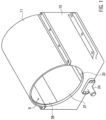
- a centrifuge 1 according to the invention ( Figure 4a ) has a rotor 2, a housing 3, a drive device 4 for rotating the rotor 2 about a rotation axis 5.
- the rotor has at least one receiving area 6 for receiving a reaction vessel unit 7.
- the reaction vessel unit 7 is usually a microtiter plate.
- Such microtiter plates can be designed with a different number of reaction vessels.
- Microtiter plates with six to 4096 reaction vessels are common, with microtiter plates with 96, 384 or 1536 reaction vessels being the most common versions.
- the individual reaction vessels are so thin that a liquid normally adheres to them solely due to capillary forces, so that even if such a microtiter plate is arranged with its openings facing downwards, the liquid does not flow out. This does not apply to microtiter plates with fewer reaction vessels, each of which is larger.
- Such a reaction vessel unit 7 can be inserted into a receiving area 6 on its own or on a carrier unit.
- a carrier unit is used which has a coupling element that can be coupled to a loading and unloading device 8.
- a loading and unloading device is, for example, described in the DE 10 2016 101 163 described. It is explained in more detail below.
- the housing 3 delimits a rotor chamber 9.
- the area of the housing 3 delimiting the rotor chamber 9 is formed from a lower shell 10, upper shell 11, front end wall 12 and rear end wall 13. Further parts of the housing, which are not shown in the attached figures, are connected to the rear end wall.
- a ball bearing 14 in which a continuous shaft 15 of the rotor 2 is rotatably mounted.
- the center line of the shaft 15 forms the axis of rotation 5.
- the axis of rotation 5 runs parallel to a base surface 16 which is formed by the underside of the lower shell 10.
- the rear end of the shaft 15 is coupled to the drive device 4.
- the further part of the housing which is connected to the rear of the housing, contains the drive device 17, the loading and unloading device 8 and a central control device (not shown) with which all components of the centrifuge 1 are controlled.
- a balcony 18 is attached to the outside of the front end wall 12 and serves to accommodate a reaction vessel unit 7.
- a loading and unloading opening 19 is formed in the front end wall 12 through which a reaction vessel unit 7 can be inserted into the rotor chamber 9 and pushed out again.
- the loading and unloading opening 19 is provided with a pivoting door 20 so that the rotor chamber can be closed.
- a dispensing unit 39 with several dispensing nozzles 40 and/or an optical detection unit, in particular in the form of a line camera, can be provided.
- the loading and unloading device 8 has a displacement rod (not shown) which can be moved with its free end horizontally through the rotor chamber 9 through a through opening 21 in the rear end wall 13.
- the loading and unloading device 8 has a linear drive for this purpose, so that the displacement rod can be moved linearly along its longitudinal direction.
- the displacement rod has a coupling element at its free end which can be coupled to a corresponding coupling element on the carrier unit or on a reaction vessel unit 7, so that the carrier unit with a reaction vessel unit or the reaction vessel unit can be moved directly by moving the displacement rod from the balcony 18 through the loading and unloading opening 19 into the rotor chamber 9, wherein the rotor 2 is arranged with a receiving area 6 adjacent to the loading and unloading opening 19, so that the carrier unit or the reaction vessel unit is moved into the receiving area 6 of the rotor 2.
- the coupling between the sliding rod and the carrier unit or the reaction vessel unit 7 can be released so that the carrier unit or the reaction vessel unit is freely movable in the rotor 2 and the rotor can be rotated accordingly with this unit.
- the carrier unit or reaction vessel unit 7 can be pushed from the receiving area 6 of the rotor 2 through the loading and unloading opening 19 back onto the balcony 18.
- the reaction vessel unit 7 can be removed from the balcony 18, for example by means of a robot.
- the lower shell 10 has a groove 22 which runs approximately parallel to the axis of rotation 5.
- the groove 22 extends from the rear end wall 13 to the area of the front end wall 12, whereby it is inclined or sloping towards the front ( Figure 4a ).
- An outlet opening 23 is formed on the front of the lower bowl 10, into which the channel 22 opens.
- a connection pin 24 to which a hose 25 can be connected is arranged on the outlet opening 23.
- the hose 25 usually opens into a receiving container (not shown) in which the liquids are collected which are spun out of the reaction vessels of the reaction vessel unit 7 in the centrifuge 1.
- the container preferably has a ventilation opening or the hose passes through the container with some play so that liquid flowing out of the centrifuge through the hose 25 does not create any counterpressure in the container.
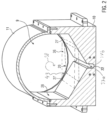
- the lower shell 10 has inner surfaces adjacent to the channel 22, which extend from an upper edge of the channel 22 in an obliquely rising direction outwards ( Fig. 2 ). These inner surfaces thus form a funnel 26 and are referred to below as funnel surfaces 27.
- the funnel surfaces 27 are inclined at an angle of approximately 30° to 60° relative to the horizontal. Essentially planar means that the funnel surfaces have a radius of curvature of more than 0.5 m and preferably more than 1 m. In the present embodiment, the funnel surfaces 27 extend laterally in the direction beyond the area of the rotor 2, even when it is in its horizontal position.
- the inner surfaces of the lower shell 10 extend approximately vertically upwards from the outer edge of the funnel 26 or the funnel surfaces 27. They thus form vertical surfaces 28.
- the upper shell 11 is attached to the upper edge of the lower shell 10 and has a channel-like shape with a semicircular cross-section.
- the inner surface of the upper shell 11 is flush with the vertical surface 28.
- the cross-section of the housing 3 is therefore not cylindrical, but only has a cylindrical curvature in the upper region of the shell 11, whereas the lower shell 10 has a funnel-shaped cross-section and ends in the channel 22.
- the channel 22 is slightly offset downwards from the funnel-shaped lower shell 10 and has two approximately vertically arranged side walls 37a, 37b.
- the channel itself is designed with an incline so that any liquid contained therein drains away.
- the lower shell 10 and the upper shell 11 are made of metal.
- the inner surfaces of the lower shell 10 and the upper shell 11 are coated with a smooth plastic layer so that liquids that are ejected from the reaction vessels of the reaction vessel units 7 run quickly along the inner surfaces, are guided from the funnel 26 to the channel 22 and exit from the rotor chamber 9.
- the plastic layer is made of PTFE.
- the upper edge of the channel 22 is spaced from the rotation axis 5 by at least 1.32 times the maximum radius of the rotor 2. This creates a free space in the funnel 26 which is not touched by the rotor 2 during one revolution. Liquid can collect in this free space.
- a maximum level 29 of the liquid is shown which can collect in the funnel 26 without coming into contact with the rotor. This makes it possible, in the case of large-volume reaction vessels of a reaction vessel unit 7, to empty the majority of the liquid contained therein at once, to collect it in the funnel 26 so that it can gradually flow out through the outlet opening 23.
- the air flow generated by the rotor when it rotates is at its lowest in this area, so that liquid can settle at the bottom of the funnel, i.e. in the channel 22, and flow out of the channel 22 through the outlet opening 23. Due to the low flow velocity, the risk of liquids located in the funnel-shaped area adjacent to the channel 22 being driven upwards by the air flow is also low.
- the channel is limited by approximately vertical side walls 37a, 37b, even if an air flow is generated in the direction of rotation 38, this can no longer drive the liquid out of the channel. Once a liquid is in the channel 22, it is thus trapped therein and can only exit through the outlet opening 23.
- an air flow can strike the side wall 37a, which is arranged in the channel 22 downstream in the direction of rotation 38 of the rotor.
- the side wall 37a is approximately perpendicular to the direction of flow, the liquid in the channel can no longer be driven back into the rotor chamber.
- a channel with an approximately vertical side wall on the side of the channel 22 downstream in the direction of rotation 38 is sufficient. From a manufacturing point of view, however, it is expedient to produce a channel with two approximately vertical side walls 37a, 37b.
- This design of the funnel 26 and the channel 22 eliminates the need for a suction pump.
- the dispensing unit 30, which can also be referred to as a dispensing head, has several of the dispensing nozzles 31, which are arranged along a straight line and with their openings pointing downwards.
- the dispensing unit 30 is connected to a reagent line 32, via which reagents are fed to the dispensing unit 30, which are then distributed downwards via the individual dispensing nozzles 31.
- the dispensing unit basically has the WO 2018/234420 A1 known function that reaction vessels of a reaction vessel unit 7 can be filled with reagents when the reaction vessel unit 7 is moved past the dispensing unit 30 by means of the loading and unloading device 8.
- the balcony 18 is formed in the area below the dispensing unit 30 with an upwardly open channel 33 in which the reagents dispensed by the dispensing nozzles 31 are collected if no reaction vessel unit 7 is arranged below the dispensing nozzles 31, as in Figure 4a
- the channel 33 is connected to a collecting tube 34 so that the reagents collected in the channel 33 flow off via the collecting tube 34.
- the collecting tube 34 opens into the tube 25 at a branch 35.
- starting from the Branch 35 of the collecting hose is a supply line and the hose 25 is a drain line for draining liquids from the rotor chamber 9.
- a blocking element 36 is arranged in the hose 25 downstream of the branch 35, with which the passage of the hose 25 can be blocked.
- the blocking element 36 can be a preferably electrically actuated valve in order to open or close the passage of the hose.
- the blocking element can also be a hose clamp, which can be opened or closed, for example, with an actuator or by means of an eccentric.
- the blocking element 36 blocks the passage of the hose 25 and a cleaning solution is supplied via the collecting hose 34 with the dispensing unit 30, the cleaning solution flows via the hose 25 and the outlet opening 23 into the rotor chamber 9.
- the outlet opening 23 then serves as an inlet for the cleaning solution.
- the rotor chamber 9 is filled to above the level 29 ( Figure 2 ) is filled with cleaning solution, so that when the rotor 2 rotates, it is immersed in the cleaning solution and takes part of the cleaning solution with it and distributes it in the rotor chamber 9.
- the rotor chamber 9 is filled at least up to a level 43, as Figure 2
- the level 43 is approximately 5% of the radius of the rotor 2 and preferably at least 10% of the radius of the rotor 2 above the level 29 which is just not touched when the rotor 2 rotates.
- the cleaning solution is distributed in the rotor chamber 9 so that all parts of the rotor chamber 9 come into contact with the cleaning solution.
- cleaning solution can continue to be supplied via the dispensing unit 30 in order to slow down or prevent the level of the cleaning solution from dropping.
- the rotation of the rotor can be adjusted or the rotor can be rotated further in order to cause a continuous swirling of the cleaning solution in the rotor chamber by the air current.
- the blocking element 36 is opened so that the cleaning solution flows out through the outlet opening 23. This can be supported by further rotation of the rotor so that the cleaning solution is driven into the channel 22.
- This cleaning process of the rotor chamber 9 can be carried out fully automatically and is controlled by the central control device.
- a non-foaming cleaning solution such as formaldehyde or paraformaldehyde, is preferably used as the cleaning solution, with which the entire rotor chamber 9 can be reliably disinfected.
- the cleaning solution contains surfactants, which cause the cleaning solution to foam when the rotor is rotated. Foaming of the cleaning solution causes the cleaning solution to be distributed very quickly and evenly in the rotor chamber 9, which is why the speed of rotation and/or duration at which the rotor is rotated in the rotor chamber 9 can or should be significantly reduced compared to the distribution of non-foaming cleaning solution.
- a foam-decomposing solution is fed to the rotor chamber 9 via the dispensing unit 30 and the collection hose 34 and distributed by rotating the rotor 2.
- foam in the rotor chamber 9 collapses and the cleaning solution flows out of the rotor chamber 9 together with the foam-decomposing solution.
- foam-decomposing solution can contain alcohol, for example.
- a solution containing alcohol also has the advantage that it evaporates very quickly and the rotor chamber 9 therefore dries accordingly quickly.
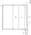
- a second embodiment of the centrifuge 1 ( Figure 4b ) is designed essentially in the same way as the first embodiment, unless explained otherwise below, which is why identical parts are given the same reference numerals and are not explained again.
- the second embodiment does not have to have a dispensing unit.
- an atomizing nozzle 40 is arranged in the feed opening 39, with which reagents supplied via the reagent line 32 are atomized into the rotor chamber 9.
- a cleaning solution By supplying a cleaning solution via the feed opening 39, this is introduced into the rotor chamber 9 and atomized by the atomizing nozzle 40 into a mist, which is evenly distributed in the rotor chamber 9 by rotating the rotor 2. A portion of the cleaning solution settles in the channel 22 and flows out of the rotor chamber 9 via the outlet opening 23 and the hose 25. This allows cleaning solution to be continuously circulated in the rotor chamber 9 and drained away in order to remove contamination from the rotor chamber 9.
- a blocking element 36 can optionally be provided in the hose 25 in order to block the passage of the hose 25 and to retain cleaning solution in the rotor chamber 9.
- an atomizing nozzle 40 in the feed opening 39. This depends on the dimensions of the rotor space, the rotor and the air flow generated thereby as the rotor rotates. Thus, sufficient distribution of the cleaning solution can be achieved without the need for atomizing nozzles simply by rotating the rotor and the air flow generated thereby.
- a pressure nozzle can also be inserted into the feed opening(s) 39.
- a pressure nozzle is a nozzle that opens when the cleaning solution is fed to the nozzle at a predetermined pressure. In this way, the time at which cleaning solution is fed into the rotor chamber can be precisely controlled.
- the pressure nozzle can also be an atomizing nozzle.
- the blocking element 36 is provided in the hose 25, as much cleaning solution can be introduced into the rotor chamber 9 via the feed opening 39 until a filling level corresponding to the level 43 of Figure 2 is achieved. Then, by rotating the rotor, as explained above using the first embodiment, the cleaning solution can be evenly distributed in the rotor chamber 9.
- the second embodiment can be modified in that the hose 25 is formed into a siphon 41 ( Figure 4b ), ie that the hose 25 is guided a little way upwards from the outlet opening 23 and is then diverted downwards so that liquid flowing into the hose 25 only overcomes the siphon when the liquid level in the rotor chamber 9 has reached the height of the siphon.
- a suction pump 42 must be provided in the hose 25 in order to completely suck the liquid out of the rotor chamber 9 via the siphon 41 if necessary, or a lifting mechanism can be provided which lowers the hose 25 in such a way that the siphon 41 is lifted and the liquid contained in the hose 25 flows out due to gravity alone.
- non-foaming cleaning solutions or foaming cleaning solutions can also be supplied. If foaming cleaning solutions are used, it is expedient, just as in the first embodiment, to supply a foam-degrading solution to the rotor chamber 9 in order to remove the foaming cleaning solution from the rotor chamber 9.
- the cleaning solution or cleaning solutions can be supplied to or removed from the rotor chamber 9 in different ways in order to clean the rotor chamber 9.
- the rotor 2 which is present in the centrifuge 1 as standard, is used to distribute the cleaning solution evenly in the rotor chamber 9.
- the rotational speed and the duration at which the rotor 2 is rotated must be adapted to the geometry of the rotor interior 9 and the behavior of the cleaning solution.
- one or more atomizing nozzles 40 it is expedient to supply the cleaning solution under pressure so that the atomizing nozzles 40 cause efficient atomization of the cleaning solution.
- the supply and even distribution as well as the removal of the cleaning solution from the rotor chamber 9 can be carried out fully automatically.
- the centrifuge 1 can be used in an automatic production process in which many reaction vessel units 7 are repeatedly cleaned, ensuring in the long term that no contamination occurs from one reaction vessel unit 7 to another reaction vessel unit 7.
- the intervals of the cleaning processes of the rotor chamber 9 must be adapted to the amount and reactivity of the reagents contained in the reaction vessel units 7.
- Such a cleaning process can, for example, be carried out at an interval of no more than 10 minutes or no more than 60 minutes. With less reactive reagents and small quantities, however, it can also be expedient to carry out such a cleaning process only once a day.
- the cleaning process can be used to completely disinfect the interior and reliably prevent contamination by viruses, bacteria or other infectious agents.
- agents can be used as solvents that destroy nucleic acids and thus exclude contamination.
- agents are, for example, perchlorate, strong oxidizing agents and/or enzymes such as DNAses.
- the system can be completely cleaned without having to open the interior or the device.
- the invention can be briefly summarized as follows:
- the invention relates to a centrifuge 1 for cleaning a reaction vessel unit 7 and to a method for cleaning such a centrifuge 1.
- the centrifuge 1 has a rotor 2 and a rotor chamber 9 in which the rotor 2 is arranged and rotatably mounted, the rotor 2 having a receiving area 6 for receiving the reaction vessel unit 7.
- the rotor chamber 9 is delimited by a housing 3, the housing 3 having an outlet for discharging liquid discharged from the reaction vessels and being provided with an inlet for filling the rotor chamber 9 with a cleaning solution in such a way that when the rotor 2 rotates, it is at least partially immersed in the cleaning solution and distributes it in the rotor chamber 9 and/or the inlet is designed such that the cleaning solution is distributed in the rotor chamber 9 when fed by the rotating rotor 2.
Landscapes
- Engineering & Computer Science (AREA)
- Mechanical Engineering (AREA)
- Health & Medical Sciences (AREA)
- Clinical Laboratory Science (AREA)
- Chemical & Material Sciences (AREA)
- Chemical Kinetics & Catalysis (AREA)
- Centrifugal Separators (AREA)
- Automatic Analysis And Handling Materials Therefor (AREA)
- Cleaning By Liquid Or Steam (AREA)
- Apparatus Associated With Microorganisms And Enzymes (AREA)
Applications Claiming Priority (2)
| Application Number | Priority Date | Filing Date | Title |
|---|---|---|---|
| DE102021124023.9A DE102021124023B4 (de) | 2021-09-16 | 2021-09-16 | Zentrifuge und Verfahren zum Reinigen einer Zentrifuge |
| EP22196177.4A EP4151315B1 (fr) | 2021-09-16 | 2022-09-16 | Centrifugeuse et procédé de nettoyage d'une centrifugeuse |
Related Parent Applications (1)
| Application Number | Title | Priority Date | Filing Date |
|---|---|---|---|
| EP22196177.4A Division EP4151315B1 (fr) | 2021-09-16 | 2022-09-16 | Centrifugeuse et procédé de nettoyage d'une centrifugeuse |
Publications (4)
| Publication Number | Publication Date |
|---|---|
| EP4484014A2 true EP4484014A2 (fr) | 2025-01-01 |
| EP4484014A3 EP4484014A3 (fr) | 2025-03-19 |
| EP4484014C0 EP4484014C0 (fr) | 2026-02-11 |
| EP4484014B1 EP4484014B1 (fr) | 2026-02-11 |
Family
ID=83361094
Family Applications (2)
| Application Number | Title | Priority Date | Filing Date |
|---|---|---|---|
| EP24213729.7A Active EP4484014B1 (fr) | 2021-09-16 | 2022-09-16 | Centrifugeuse et procédé de nettoyage d'une centrifugeuse |
| EP22196177.4A Active EP4151315B1 (fr) | 2021-09-16 | 2022-09-16 | Centrifugeuse et procédé de nettoyage d'une centrifugeuse |
Family Applications After (1)
| Application Number | Title | Priority Date | Filing Date |
|---|---|---|---|
| EP22196177.4A Active EP4151315B1 (fr) | 2021-09-16 | 2022-09-16 | Centrifugeuse et procédé de nettoyage d'une centrifugeuse |
Country Status (5)
| Country | Link |
|---|---|
| US (1) | US12383907B2 (fr) |
| EP (2) | EP4484014B1 (fr) |
| JP (1) | JP2023047313A (fr) |
| CN (1) | CN115805145A (fr) |
| DE (1) | DE102021124023B4 (fr) |
Families Citing this family (7)
| Publication number | Priority date | Publication date | Assignee | Title |
|---|---|---|---|---|
| DE102017113583A1 (de) * | 2017-06-20 | 2018-12-20 | Bluecatbio Gmbh | Zentrifuge |
| DE102022102705A1 (de) | 2022-02-04 | 2023-08-10 | BlueCat Solutions GmbH | Auffangvorrichtung für eine Reaktionsgefäßeinheit und Reaktionsgefäßeinheit |
| DE102022102701A1 (de) | 2022-02-04 | 2023-08-10 | Bluecatbio Gmbh | Ableitvorrichtung für eine Reaktionsgefäßeinheit, Zentrifuge und Verfahren zum Reinigen einer Reaktionsgefäßeinheit |
| DE102023120681A1 (de) | 2023-08-03 | 2025-02-06 | Bluecatbio Gmbh | Ableitvorrichtung für das Zentrifugieren einer Reaktionsgefäßeinheit, Zentrifuge und Verfahren zum Reinigen einer Ableitvorrichtung |
| DE202023105780U1 (de) | 2023-10-05 | 2025-01-28 | Bluecatbio Gmbh | Rückhaltevorrichtung für eine Reaktionsgefäßeinheit |
| DE202023105800U1 (de) | 2023-10-06 | 2025-01-28 | Bluecatbio Gmbh | Magnetträger für Reaktionsgefäßeinheiten |
| DE202023105801U1 (de) | 2023-10-06 | 2025-01-28 | Bluecatbio Gmbh | Wuchtkörper |
Citations (14)
| Publication number | Priority date | Publication date | Assignee | Title |
|---|---|---|---|---|
| DE2404036A1 (de) | 1974-01-29 | 1975-07-31 | Heraeus Christ Gmbh | Zentrifuge zur behandlung biologischer fluessigkeiten wie blut |
| JPS5143967U (fr) | 1974-09-28 | 1976-03-31 | ||
| US4953575A (en) | 1988-09-30 | 1990-09-04 | Labsystems Oy | Washing device |
| EP0937502A2 (fr) | 1997-12-15 | 1999-08-25 | Wallac Oy | Méthode et appareil pour manipuler les plaques porte-échantillons |
| DE10355179A1 (de) | 2003-11-26 | 2005-06-30 | Kendro Laboratory Products Gmbh | Luftgekühlte Zentrifuge |
| US20070037684A1 (en) | 2005-08-10 | 2007-02-15 | Moscone Kenneth J Sr | Centrifuge bucket design |
| JP2007178355A (ja) | 2005-12-28 | 2007-07-12 | Nippon Support System Kk | 試薬廃棄装置 |
| JP2009264927A (ja) | 2008-04-25 | 2009-11-12 | Micronics Kk | マイクロプレート処理装置 |
| CN102175855A (zh) | 2011-01-13 | 2011-09-07 | 邱重任 | 一种全自动360度甩干的卧式酶标洗板机 |
| EP2705903A1 (fr) | 2012-09-06 | 2014-03-12 | Eppendorf AG | Dispositif à rotor, cuvette de centrifugation et centrifugeuse ainsi que leur procédé de fabrication |
| WO2015018878A2 (fr) | 2013-08-06 | 2015-02-12 | Yantai Ausbio Laboratories Co., Ltd. | Centrifugeuse et procédé de centrifugation d'une unité de récipient de réaction |
| DE102016101163A1 (de) | 2016-01-22 | 2017-07-27 | Bluecatbio Gmbh | Zentrifuge |
| WO2018234420A1 (fr) | 2017-06-20 | 2018-12-27 | Bluecatbio Gmbh | Centrifugeuse |
| CN113000230A (zh) | 2021-02-24 | 2021-06-22 | 安徽中科中佳科学仪器有限公司 | 一种杀菌消毒自清洁的实验室医用离心机 |
Family Cites Families (8)
| Publication number | Priority date | Publication date | Assignee | Title |
|---|---|---|---|---|
| DE1033446B (de) * | 1955-05-13 | 1958-07-03 | Martin Christ Fa | Gekuehlter Rotorraum fuer hochtourige Laborzentrifuge |
| CH615604A5 (fr) * | 1977-02-22 | 1980-02-15 | Escher Wyss Ag | |
| DE3633528C2 (de) * | 1986-10-02 | 1996-03-07 | Duerr Dental Gmbh Co Kg | Verfahren zum Messen der Mächtigkeit einer Feststoffschicht auf der Umfangswand einer Zentrifugentrommel und Vorrichtung zur Durchführung des Verfahrens |
| SE459234B (sv) * | 1987-10-15 | 1989-06-19 | Alfa Laval Marine Power Eng | Saett och utrustning foer invaendig diskning av en centrifugrotor |
| EP1033446A1 (fr) | 1999-03-04 | 2000-09-06 | Gert Dr. Dallach | Procédé de construction d'une structure de fondation dans une excavation remplie d'eau |
| US6867174B2 (en) * | 2001-04-16 | 2005-03-15 | Bissell Homecare, Inc. | Non-foaming cleaning compositions and a method for their use |
| JP3676346B2 (ja) * | 2003-01-30 | 2005-07-27 | 月島機械株式会社 | 遠心分離機、遠心分離機の洗浄方法 |
| DE10331732A1 (de) * | 2003-07-11 | 2005-02-10 | Westfalia Separator Ag | Zentrifuge |
-
2021
- 2021-09-16 DE DE102021124023.9A patent/DE102021124023B4/de active Active
-
2022
- 2022-09-09 US US17/941,262 patent/US12383907B2/en active Active
- 2022-09-12 JP JP2022144670A patent/JP2023047313A/ja active Pending
- 2022-09-15 CN CN202211123394.0A patent/CN115805145A/zh active Pending
- 2022-09-16 EP EP24213729.7A patent/EP4484014B1/fr active Active
- 2022-09-16 EP EP22196177.4A patent/EP4151315B1/fr active Active
Patent Citations (15)
| Publication number | Priority date | Publication date | Assignee | Title |
|---|---|---|---|---|
| DE2404036A1 (de) | 1974-01-29 | 1975-07-31 | Heraeus Christ Gmbh | Zentrifuge zur behandlung biologischer fluessigkeiten wie blut |
| JPS5143967U (fr) | 1974-09-28 | 1976-03-31 | ||
| US4953575A (en) | 1988-09-30 | 1990-09-04 | Labsystems Oy | Washing device |
| EP0937502A2 (fr) | 1997-12-15 | 1999-08-25 | Wallac Oy | Méthode et appareil pour manipuler les plaques porte-échantillons |
| DE10355179A1 (de) | 2003-11-26 | 2005-06-30 | Kendro Laboratory Products Gmbh | Luftgekühlte Zentrifuge |
| US20070037684A1 (en) | 2005-08-10 | 2007-02-15 | Moscone Kenneth J Sr | Centrifuge bucket design |
| JP2007178355A (ja) | 2005-12-28 | 2007-07-12 | Nippon Support System Kk | 試薬廃棄装置 |
| JP2009264927A (ja) | 2008-04-25 | 2009-11-12 | Micronics Kk | マイクロプレート処理装置 |
| CN102175855A (zh) | 2011-01-13 | 2011-09-07 | 邱重任 | 一种全自动360度甩干的卧式酶标洗板机 |
| EP2705903A1 (fr) | 2012-09-06 | 2014-03-12 | Eppendorf AG | Dispositif à rotor, cuvette de centrifugation et centrifugeuse ainsi que leur procédé de fabrication |
| WO2015018878A2 (fr) | 2013-08-06 | 2015-02-12 | Yantai Ausbio Laboratories Co., Ltd. | Centrifugeuse et procédé de centrifugation d'une unité de récipient de réaction |
| DE102016101163A1 (de) | 2016-01-22 | 2017-07-27 | Bluecatbio Gmbh | Zentrifuge |
| WO2017125598A1 (fr) | 2016-01-22 | 2017-07-27 | Bluecatbio Gmbh | Centrifugeuse |
| WO2018234420A1 (fr) | 2017-06-20 | 2018-12-27 | Bluecatbio Gmbh | Centrifugeuse |
| CN113000230A (zh) | 2021-02-24 | 2021-06-22 | 安徽中科中佳科学仪器有限公司 | 一种杀菌消毒自清洁的实验室医用离心机 |
Also Published As
| Publication number | Publication date |
|---|---|
| EP4151315B1 (fr) | 2024-11-20 |
| DE102021124023A1 (de) | 2023-03-16 |
| DE102021124023B4 (de) | 2025-07-17 |
| EP4151315A1 (fr) | 2023-03-22 |
| JP2023047313A (ja) | 2023-04-05 |
| EP4484014C0 (fr) | 2026-02-11 |
| US12383907B2 (en) | 2025-08-12 |
| CN115805145A (zh) | 2023-03-17 |
| US20230077651A1 (en) | 2023-03-16 |
| EP4484014A3 (fr) | 2025-03-19 |
| EP4484014B1 (fr) | 2026-02-11 |
| EP4151315C0 (fr) | 2024-11-20 |
Similar Documents
| Publication | Publication Date | Title |
|---|---|---|
| EP4151315B1 (fr) | Centrifugeuse et procédé de nettoyage d'une centrifugeuse | |
| EP3641943B1 (fr) | Centrifugeuse | |
| EP0973620B2 (fr) | Procede et dispositif pour nettoyer ou secher des pieces | |
| DE68905970T2 (de) | Chemikalien-Ausgabegerät. | |
| EP3438674A1 (fr) | Procédé et dispositif de nettoyage des aiguilles de pipetage | |
| DE69736762T2 (de) | Pipettenreinigungseinheit für automatische biochemische Analysiervorrichtung | |
| DE102021121265B4 (de) | Dispensiervorrichtung, Zentrifuge mit einer solchen Dispensiervorrichtung und Verfahren zum Reinigen von Dispensierdüsen | |
| WO2000011130A1 (fr) | Nettoyage des graisses au moyen d'un solvant de graisses | |
| EP0297371A1 (fr) | Doseur pour poudre | |
| DE69805156T2 (de) | Verfahren und Vorrichtung zur Behandlung von Musterplatten | |
| EP4472776B1 (fr) | Dispositif d'évacuation pour un ensemble récipient de réaction, centrifugeuse et procédé de nettoyage d'un ensemble récipient de réaction | |
| DE3238679C2 (de) | Verfahren zum Reinigen rohrförmiger Probenbehälter eines automatischen Analysiergerätes | |
| DE102004037848B4 (de) | Probenträgerwaschbehälter, Probenträgerwaschstation, System zum Waschen von Probenträgern und Verfahren zum Waschen von Probenträgern | |
| EP4472777B1 (fr) | Dispositif de collecte pour un ensemble récipient de réaction et ensemble récipient de réaction | |
| DE60129868T2 (de) | Verfahren zum Rühren einer Flüssigkeit | |
| DE2330136C2 (de) | Verfahren zur Reinigung der Innen-und/oder Außenseite eines Gefässes und Einrichtung zur Durchführung des Verfahrens | |
| WO2022198252A1 (fr) | Dispositif et procédé pour retirer un matériau auxiliaire de pièces imprimées en 3d | |
| DE19914746A1 (de) | Ultraschallwaschvorrichtung und Ultraschallwaschsystem | |
| DE2804729A1 (de) | Verfahren zum waschen und trocknen von schuettgut, insbesondere zerkleinerten kunststoffabfaellen, sowie vorrichtung zur durchfuehrung des verfahrens | |
| WO1995019212A1 (fr) | Dispositif de nettoyage de solides contenus dans des eaux residuaires | |
| DE102019107623A1 (de) | Dosiersystem | |
| DE9406044U1 (de) | Reinigungsvorrichtung | |
| WO2025027173A1 (fr) | Dispositif de décharge pour centrifuger un ensemble cuve de réaction, centrifugeuse et procédé de nettoyage d'un dispositif de décharge | |
| DE2645854C2 (fr) | ||
| DE3422745A1 (de) | Verfahren und vorrichtung zum saeurepolieren von gegenstaenden aus glas |
Legal Events
| Date | Code | Title | Description |
|---|---|---|---|
| PUAI | Public reference made under article 153(3) epc to a published international application that has entered the european phase |
Free format text: ORIGINAL CODE: 0009012 |
|
| STAA | Information on the status of an ep patent application or granted ep patent |
Free format text: STATUS: THE APPLICATION HAS BEEN PUBLISHED |
|
| AC | Divisional application: reference to earlier application |
Ref document number: 4151315 Country of ref document: EP Kind code of ref document: P |
|
| AK | Designated contracting states |
Kind code of ref document: A2 Designated state(s): AL AT BE BG CH CY CZ DE DK EE ES FI FR GB GR HR HU IE IS IT LI LT LU LV MC MK MT NL NO PL PT RO RS SE SI SK SM TR |
|
| PUAL | Search report despatched |
Free format text: ORIGINAL CODE: 0009013 |
|
| AK | Designated contracting states |
Kind code of ref document: A3 Designated state(s): AL AT BE BG CH CY CZ DE DK EE ES FI FR GB GR HR HU IE IS IT LI LT LU LV MC MK MT NL NO PL PT RO RS SE SI SK SM TR |
|
| RIC1 | Information provided on ipc code assigned before grant |
Ipc: B04B 13/00 20060101ALI20250212BHEP Ipc: B04B 11/04 20060101ALI20250212BHEP Ipc: B04B 15/06 20060101ALI20250212BHEP Ipc: B04B 7/02 20060101ALI20250212BHEP Ipc: B04B 5/04 20060101AFI20250212BHEP |
|
| STAA | Information on the status of an ep patent application or granted ep patent |
Free format text: STATUS: REQUEST FOR EXAMINATION WAS MADE |
|
| 17P | Request for examination filed |
Effective date: 20250603 |
|
| GRAP | Despatch of communication of intention to grant a patent |
Free format text: ORIGINAL CODE: EPIDOSNIGR1 |
|
| STAA | Information on the status of an ep patent application or granted ep patent |
Free format text: STATUS: GRANT OF PATENT IS INTENDED |
|
| INTG | Intention to grant announced |
Effective date: 20251007 |
|
| GRAS | Grant fee paid |
Free format text: ORIGINAL CODE: EPIDOSNIGR3 |
|
| GRAA | (expected) grant |
Free format text: ORIGINAL CODE: 0009210 |
|
| STAA | Information on the status of an ep patent application or granted ep patent |
Free format text: STATUS: THE PATENT HAS BEEN GRANTED |
|
| AC | Divisional application: reference to earlier application |
Ref document number: 4151315 Country of ref document: EP Kind code of ref document: P |
|
| AK | Designated contracting states |
Kind code of ref document: B1 Designated state(s): AL AT BE BG CH CY CZ DE DK EE ES FI FR GB GR HR HU IE IS IT LI LT LU LV MC MK MT NL NO PL PT RO RS SE SI SK SM TR |
|
| REG | Reference to a national code |
Ref country code: CH Ref legal event code: F10 Free format text: ST27 STATUS EVENT CODE: U-0-0-F10-F00 (AS PROVIDED BY THE NATIONAL OFFICE) Effective date: 20260211 Ref country code: GB Ref legal event code: FG4D Free format text: NOT ENGLISH |
|
| REG | Reference to a national code |
Ref country code: IE Ref legal event code: FG4D Free format text: LANGUAGE OF EP DOCUMENT: GERMAN |
|
| U01 | Request for unitary effect filed |
Effective date: 20260211 |
|
| U07 | Unitary effect registered |
Designated state(s): AT BE BG DE DK EE FI FR IT LT LU LV MT NL PT RO SE SI Effective date: 20260217 |