EP4484018A1 - Beschichtungsvorrichtung und beschichtungsverfahren - Google Patents
Beschichtungsvorrichtung und beschichtungsverfahren Download PDFInfo
- Publication number
- EP4484018A1 EP4484018A1 EP22926320.7A EP22926320A EP4484018A1 EP 4484018 A1 EP4484018 A1 EP 4484018A1 EP 22926320 A EP22926320 A EP 22926320A EP 4484018 A1 EP4484018 A1 EP 4484018A1
- Authority
- EP
- European Patent Office
- Prior art keywords
- nozzles
- coating
- detector
- holding portions
- bar
- Prior art date
- Legal status (The legal status is an assumption and is not a legal conclusion. Google has not performed a legal analysis and makes no representation as to the accuracy of the status listed.)
- Pending
Links
Images




Classifications
-
- B—PERFORMING OPERATIONS; TRANSPORTING
- B05—SPRAYING OR ATOMISING IN GENERAL; APPLYING FLUENT MATERIALS TO SURFACES, IN GENERAL
- B05C—APPARATUS FOR APPLYING FLUENT MATERIALS TO SURFACES, IN GENERAL
- B05C1/00—Apparatus in which liquid or other fluent material is applied to the surface of the work by contact with a member carrying the liquid or other fluent material, e.g. a porous member loaded with a liquid to be applied as a coating
- B05C1/04—Apparatus in which liquid or other fluent material is applied to the surface of the work by contact with a member carrying the liquid or other fluent material, e.g. a porous member loaded with a liquid to be applied as a coating for applying liquid or other fluent material to work of indefinite length
- B05C1/08—Apparatus in which liquid or other fluent material is applied to the surface of the work by contact with a member carrying the liquid or other fluent material, e.g. a porous member loaded with a liquid to be applied as a coating for applying liquid or other fluent material to work of indefinite length using a roller or other rotating member which contacts the work along a generating line
- B05C1/0804—Apparatus in which liquid or other fluent material is applied to the surface of the work by contact with a member carrying the liquid or other fluent material, e.g. a porous member loaded with a liquid to be applied as a coating for applying liquid or other fluent material to work of indefinite length using a roller or other rotating member which contacts the work along a generating line the material being applied without contact with the roller
-
- B—PERFORMING OPERATIONS; TRANSPORTING
- B05—SPRAYING OR ATOMISING IN GENERAL; APPLYING FLUENT MATERIALS TO SURFACES, IN GENERAL
- B05C—APPARATUS FOR APPLYING FLUENT MATERIALS TO SURFACES, IN GENERAL
- B05C1/00—Apparatus in which liquid or other fluent material is applied to the surface of the work by contact with a member carrying the liquid or other fluent material, e.g. a porous member loaded with a liquid to be applied as a coating
- B05C1/04—Apparatus in which liquid or other fluent material is applied to the surface of the work by contact with a member carrying the liquid or other fluent material, e.g. a porous member loaded with a liquid to be applied as a coating for applying liquid or other fluent material to work of indefinite length
- B05C1/08—Apparatus in which liquid or other fluent material is applied to the surface of the work by contact with a member carrying the liquid or other fluent material, e.g. a porous member loaded with a liquid to be applied as a coating for applying liquid or other fluent material to work of indefinite length using a roller or other rotating member which contacts the work along a generating line
- B05C1/0813—Apparatus in which liquid or other fluent material is applied to the surface of the work by contact with a member carrying the liquid or other fluent material, e.g. a porous member loaded with a liquid to be applied as a coating for applying liquid or other fluent material to work of indefinite length using a roller or other rotating member which contacts the work along a generating line characterised by means for supplying liquid or other fluent material to the roller
-
- B—PERFORMING OPERATIONS; TRANSPORTING
- B05—SPRAYING OR ATOMISING IN GENERAL; APPLYING FLUENT MATERIALS TO SURFACES, IN GENERAL
- B05C—APPARATUS FOR APPLYING FLUENT MATERIALS TO SURFACES, IN GENERAL
- B05C5/00—Apparatus in which liquid or other fluent material is projected, poured or allowed to flow on to the surface of the work
- B05C5/02—Apparatus in which liquid or other fluent material is projected, poured or allowed to flow on to the surface of the work the liquid or other fluent material being discharged through an outlet orifice by pressure, e.g. from an outlet device in contact or almost in contact, with the work
- B05C5/027—Coating heads with several outlets, e.g. aligned transversally to the moving direction of a web to be coated
- B05C5/0275—Coating heads with several outlets, e.g. aligned transversally to the moving direction of a web to be coated flow controlled, e.g. by a valve
-
- B—PERFORMING OPERATIONS; TRANSPORTING
- B05—SPRAYING OR ATOMISING IN GENERAL; APPLYING FLUENT MATERIALS TO SURFACES, IN GENERAL
- B05C—APPARATUS FOR APPLYING FLUENT MATERIALS TO SURFACES, IN GENERAL
- B05C5/00—Apparatus in which liquid or other fluent material is projected, poured or allowed to flow on to the surface of the work
- B05C5/02—Apparatus in which liquid or other fluent material is projected, poured or allowed to flow on to the surface of the work the liquid or other fluent material being discharged through an outlet orifice by pressure, e.g. from an outlet device in contact or almost in contact, with the work
- B05C5/0291—Apparatus in which liquid or other fluent material is projected, poured or allowed to flow on to the surface of the work the liquid or other fluent material being discharged through an outlet orifice by pressure, e.g. from an outlet device in contact or almost in contact, with the work the material being discharged on the work through discrete orifices as discrete droplets, beads or strips that coalesce on the work or are spread on the work so as to form a continuous coating
-
- B—PERFORMING OPERATIONS; TRANSPORTING
- B05—SPRAYING OR ATOMISING IN GENERAL; APPLYING FLUENT MATERIALS TO SURFACES, IN GENERAL
- B05D—PROCESSES FOR APPLYING FLUENT MATERIALS TO SURFACES, IN GENERAL
- B05D1/00—Processes for applying liquids or other fluent materials
- B05D1/28—Processes for applying liquids or other fluent materials performed by transfer from the surfaces of elements carrying the liquid or other fluent material, e.g. brushes, pads, rollers
-
- B—PERFORMING OPERATIONS; TRANSPORTING
- B05—SPRAYING OR ATOMISING IN GENERAL; APPLYING FLUENT MATERIALS TO SURFACES, IN GENERAL
- B05D—PROCESSES FOR APPLYING FLUENT MATERIALS TO SURFACES, IN GENERAL
- B05D1/00—Processes for applying liquids or other fluent materials
- B05D1/26—Processes for applying liquids or other fluent materials performed by applying the liquid or other fluent material from an outlet device in contact with, or almost in contact with, the surface
-
- B—PERFORMING OPERATIONS; TRANSPORTING
- B05—SPRAYING OR ATOMISING IN GENERAL; APPLYING FLUENT MATERIALS TO SURFACES, IN GENERAL
- B05D—PROCESSES FOR APPLYING FLUENT MATERIALS TO SURFACES, IN GENERAL
- B05D1/00—Processes for applying liquids or other fluent materials
- B05D1/40—Distributing applied liquids or other fluent materials by members moving relatively to surface
- B05D1/42—Distributing applied liquids or other fluent materials by members moving relatively to surface by non-rotary members
-
- B—PERFORMING OPERATIONS; TRANSPORTING
- B05—SPRAYING OR ATOMISING IN GENERAL; APPLYING FLUENT MATERIALS TO SURFACES, IN GENERAL
- B05D—PROCESSES FOR APPLYING FLUENT MATERIALS TO SURFACES, IN GENERAL
- B05D2201/00—Polymeric substrate or laminate
- B05D2201/02—Polymeric substrate
-
- B—PERFORMING OPERATIONS; TRANSPORTING
- B05—SPRAYING OR ATOMISING IN GENERAL; APPLYING FLUENT MATERIALS TO SURFACES, IN GENERAL
- B05D—PROCESSES FOR APPLYING FLUENT MATERIALS TO SURFACES, IN GENERAL
- B05D2252/00—Sheets
- B05D2252/02—Sheets of indefinite length
-
- B—PERFORMING OPERATIONS; TRANSPORTING
- B05—SPRAYING OR ATOMISING IN GENERAL; APPLYING FLUENT MATERIALS TO SURFACES, IN GENERAL
- B05D—PROCESSES FOR APPLYING FLUENT MATERIALS TO SURFACES, IN GENERAL
- B05D3/00—Pretreatment of surfaces to which liquids or other fluent materials are to be applied; After-treatment of applied coatings, e.g. intermediate treating of an applied coating preparatory to subsequent applications of liquids or other fluent materials
- B05D3/04—Pretreatment of surfaces to which liquids or other fluent materials are to be applied; After-treatment of applied coatings, e.g. intermediate treating of an applied coating preparatory to subsequent applications of liquids or other fluent materials by exposure to gases
- B05D3/0406—Pretreatment of surfaces to which liquids or other fluent materials are to be applied; After-treatment of applied coatings, e.g. intermediate treating of an applied coating preparatory to subsequent applications of liquids or other fluent materials by exposure to gases the gas being air
- B05D3/0413—Heating with air
-
- B—PERFORMING OPERATIONS; TRANSPORTING
- B05—SPRAYING OR ATOMISING IN GENERAL; APPLYING FLUENT MATERIALS TO SURFACES, IN GENERAL
- B05D—PROCESSES FOR APPLYING FLUENT MATERIALS TO SURFACES, IN GENERAL
- B05D7/00—Processes, other than flocking, specially adapted for applying liquids or other fluent materials to particular surfaces or for applying particular liquids or other fluent materials
- B05D7/02—Processes, other than flocking, specially adapted for applying liquids or other fluent materials to particular surfaces or for applying particular liquids or other fluent materials to macromolecular substances, e.g. rubber
- B05D7/04—Processes, other than flocking, specially adapted for applying liquids or other fluent materials to particular surfaces or for applying particular liquids or other fluent materials to macromolecular substances, e.g. rubber to surfaces of films or sheets
Definitions
- Embodiment of the invention relates to a coating apparatus and a coating method.
- a coating head that coats a liquid by using a coating bar.
- a coating apparatus that can form a uniform coated film is desirable.
- Patent Document 1 JP 2016-174992 A (Kokai)
- the embodiments of the invention provide a coating apparatus and a coating method in which a uniform coated film can be formed.
- a coating apparatus includes a coating bar, a plurality of nozzles, a plurality of holding portions, and a detector.
- the coating bar is configured to face a coating target member.
- the plurality of nozzles are configured to supply a liquid toward the coating bar.
- One of the plurality of holding portions holds one of the plurality of nozzles.
- the one of the plurality of holding portions is configured to control a position of the one of the plurality of nozzles relative to the coating bar.
- the detector is configured to detect a quantity corresponding to respective positions of the plurality of nozzles with respect to the coating bar.
- FIG. 1 is a schematic plan view illustrating a coating apparatus according to a first embodiment.
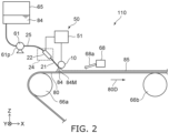
- FIG. 2 is a schematic side view illustrating the coating apparatus according to the first embodiment.
- a coating apparatus 110 includes a coating bar 10, a plurality of nozzles 21, a plurality of holding portions 22, and a detector 50.
- the coating bar 10 can face a coating target member 80.
- the plurality of nozzles 21 can supply liquid 84 toward coating bar 10.
- a coating film 85 is formed on the coating target member 80 by the liquid 84 discharged from the plurality of nozzles 21.
- One of the plurality of holding portions 22 holds one of the plurality of nozzles 21.
- One of the plurality of holding portions 22 can control the position of one of the plurality of nozzles 21 with respect to the coating bar 10.
- the respective positions of the plurality of nozzles 21 are fixed by the plurality of holding portions 22.
- the position is a position with the coating bar 10 as a reference.
- the detector 50 can detect a quantity corresponding to each position of the plurality of nozzles 21 with respect to the coating bar 10.
- the detected quantity may include, for example, electrical resistance, sound, stress, light, and/or images.
- the detected quantity includes a quantity relating to the contact state with the coating bar 10 in the plurality of nozzles 21.
- the contact state includes the contact area of each of the plurality of nozzles 21 with the coating bar 10.
- the contact state may include the angle of each of the plurality of nozzles 21 with respect to the coating bar.
- the states of the plurality of nozzles 21 can be controlled by the plurality of holding portions 22 based on the detected results of the quantity corresponding to the positions of the plurality of nozzles 21.
- the spatial positional relationship of each of the plurality of nozzles 21 can be made uniform with respect to the coating bar 10. Thereby, the coating film 85 being uniform is obtained.
- a coating apparatus capable of forming the coating film 85 being uniform can be provided.
- each of the plurality of nozzles 21 is in contact with the coating bar 10 in the coating.
- Each of the plurality of nozzles 21 contacts the coating bar 10 when the liquid 84 is supplied from the plurality of nozzles 21. Thereby, the positional relationship between the plurality of nozzles 21 and the coating bar 10 is stabilized. As a result, the coating state can be made uniform to some extent.
- the uniformity of the coating film 85 may be insufficient if the contact state of the plurality of nozzles 21 with the coating bar 10 is different.
- the detector 50 can detect the contact state of each of the plurality of nozzles with the coating bar 10.
- the detector 50 can detect not only contact or noncontact but also the quantity corresponding to the area of the contact.
- the coating film 85 being more uniform can be obtained by detecting the contact state of each of the plurality of nozzles with the coating bar 10.
- the contact angle may be detected by the detector 50.
- the contact area or contact angle between each of the plurality of nozzles 21 and the coating bar 10 changes, the electrical resistance between each of the plurality of nozzles 21 and the coating bar 10 changes.
- sounds generated from the plurality of nozzles 21 change.
- the contact area, contact angle, or the like changes, the stress received by each of the plurality of nozzles 21 changes.
- light for example, reflected light
- the contact area, contact angle, or the like changes, the shapes of the plurality of nozzles 21 change, and the images of the plurality of nozzles 21 change.
- the detector 50 can detect these changes.
- the plurality of holding portions 22 are controlled such that these quantities for the plurality of nozzles 21 are detected and the detected quantities are uniform among the plurality of nozzles 21. Thereby, the contact state of the plurality of nozzles 21 with the coating bar 10 can be made uniform.
- the coating apparatus 110 may include a controller 70.
- the controller 70 controls the plurality of holding portions 22 based on the quantity detected by the detector 50. Thereby, the position (contact state) of each of the plurality of nozzles 21 with respect to the coating bar 10 is appropriately controlled.
- the detector 50 may detect the contact of at least one of the plurality of nozzles 21 with the coating bar 10.
- a meniscus 84M is formed by the liquid supplied from the plurality of nozzles 21 between the coating target member 80 and the coating bar 10.
- the meniscus 84M contacts the surface of the coating target member 80.
- the coating film 85 is formed on the coating target member 80 with the liquid 84.
- the coating apparatus 110 includes a first transporter 66a and a second transporter 66b. These transporters are, for example, rollers.
- the coating target member 80 being sheet-shaped is moved along the transport direction 80D by these transporters.
- the meniscus 84M contacts a portion of the coating target member 80. In this example, roll-to-roll coating is performed.
- the coating bar 10 extends along one direction.
- the one direction is, for example, a Y-axis direction.
- One direction perpendicular to the Y-axis direction is defined as an X-axis direction.
- a direction perpendicular to the Y-axis direction and the X-axis direction is defined as a Z-axis direction.
- the transport direction 80D crosses the Y-axis direction.
- the transport direction 80D is the X-axis direction.
- the Z-axis direction corresponds to, for example, the height direction.
- the plurality of nozzles 21 may extend substantially along the transport direction 80D.
- the plurality of nozzles 21 may be inclined with respect to the transport direction 80D within the X-Z plane.
- the liquid 84 is stored in a container 65.
- the liquid 84 is supplied to the plurality of nozzles 21 through the supply pipe 25 by the supply portion 61.
- the supply portion 61 is, for example, a pump 61p.
- a plurality of pumps 61p are provided.
- one of the plurality of pumps 61p is connected to a plurality of supply pipes 25.
- One of the plurality of supply pipes 25 is connected to one of the plurality of nozzles 21.
- the liquid 84 is supplied to the plurality of nozzles 21 by one of the plurality of pumps 61p.
- the coating apparatus 110 may include a support portion 24.
- the support portion 24 supports the plurality of holding portions 22.
- the support portion 24 can change the extending direction of the plurality of nozzles 21 by controlling the plurality of holding portions 22, for example, the angle of the extending direction of the support portion 24 (the angle along the rotation direction about the Z-axis direction) may be changed.
- the angle of the extending direction of the support portion 24 (the angle along the rotation direction about the Z-axis direction) may be changed.
- the extending direction of the plurality of nozzles 21 may be collectively changed.
- the support portion 24 can change the relative positions of the plurality of holding portions 22 with respect to the coating bar 10.
- the relative positions include, for example, positions in the X-axis direction and the Z-axis direction.
- the relative position includes, for example, the angle of the direction in which the plurality of holding portions 22 are arranged.
- the coating apparatus 110 may include a drying portion 68.
- the drying portion 68 can supply gas, heat, or the like toward the coating film 85.
- the gas may be, for example, heated air. Drying of the coating film 85 is accelerated.
- the desired film may be obtained by drying the coating film 85 to become solid.
- the drying portion 68 may include, for example, air nozzles or far-infrared lamps.
- the detector 50 includes a resistance detector 51.
- the resistance detector 51 can detect electrical resistance between each of the plurality of nozzles 21 and the coating bar 10.
- the resistance detector 51 may include, for example, a resistance measurement circuit, a current measurement circuit, or a voltage measurement circuit.
- the coating apparatus 110 includes a plurality of terminals (terminals T1 to T4).
- One of the plurality of terminals is electrically connected to one of the plurality of nozzles 21.
- Another one of the plurality of terminals is electrically connected to another one of the plurality of nozzles 21.
- the resistance detector 51 is electrically connected to the plurality of nozzles 21 via the plurality of terminals.
- the resistance detector 51 is electrically connected to the coating bar 10. With such a configuration, the resistance detector 51 detects electrical resistance between each of the plurality of nozzles 21 and the coating bar 10.
- a suitable electrical resistance range is between not less than 10 ⁇ and not more than 50 ⁇ .
- a uniform coating film can be obtained by setting each of the plurality of nozzles 21 within this range.
- FIG. 3 is a schematic plan view illustrating the coating apparatus according to the first embodiment.
- the controller 70 can supply control signals (control signals Sc1 to Sc4, etc.) to each of the plurality of holding portions 22.
- the control signal is based on the quantity detected by the detector 50 (the quantity corresponding to the contact state). Thereby, the contact state of each of the plurality of nozzles 21 held by the plurality of holding portions 22 is controlled.
- the controller 70 can control the plurality of holding portions 22 based on the quantity detected by the detector 50.
- the controller 70 can cause the holding portions 22 to control the positions (contact states) of the nozzles 21 with respect to the coating bar 10.
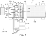
- FIG. 4 is a schematic plan view illustrating a coating apparatus according to the first embodiment.
- the detector 50 includes a sound detector 52.
- the sound detector 52 can detect sounds generated from each of the plurality of nozzles 2.
- the sound may include ultrasonic wave.
- Other configurations of the coating apparatus 111 may be the same as the configuration of the coating apparatus 110.
- the sound detector 52 may include, for example, a plurality of sound detecting elements (such as elements 52a to 52d). One of the plurality of sound detecting elements detects sound emitted from one of the plurality of nozzles 21. Another one of the plurality of sound detecting elements detects sound emitted from another one of the plurality of nozzles 21. With such a configuration, sounds generated from each of the plurality of nozzles 21 are detected. The sound detector 52 detects the volume of sound, frequency components included in the sound, and the like.
- the controller 70 can compare the detected sound with a threshold value. (control signals Sc1 to Sc4, etc.) corresponding to the comparison results are supplied from the controller 70 to the plurality of holding portions 22. The contact state of the plurality of nozzles 21 is controlled by the plurality of holding portions 22. The coating film 85 being uniform is obtained.
- FIG. 5 is a schematic plan view illustrating a coating apparatus according to the first embodiment.
- the detector 50 includes a stress detector 53.
- the stress detector 53 can detect stress applied to each of the plurality of nozzles 21.
- Other configurations of the coating apparatus 112 may be the same as the configurations of the coating apparatus 110.
- the stress detector 53 may include a plurality of stress detecting elements (such as elements 53a to 53d).
- One of the plurality of stress detecting elements is provided on one of the plurality of holding portions 22.
- Another one of the plurality of stress detecting elements is provided on another one of the plurality of holding portions 22.
- a stress applied to each of the plurality of nozzles 21 is detected by the plurality of stress detecting elements.
- the plurality of stress detecting elements are electrically connected to the circuit portion of the stress detector 53 via the plurality of terminals (terminals T1 to T4, etc.).
- lower and upper thresholds can be defined for stress.
- the controller 70 can compare the detected stress with the threshold values. (control signals Sc1 to Sc4, etc.) corresponding to the comparison results are supplied from the controller 70 to the plurality of holding portions 22.
- the contact state of the plurality of nozzles 21 is controlled by the plurality of holding portions 22.
- the coating film 85 being uniform is obtained.
- the plurality of stress detecting elements may include, for example, piezoelectric elements.
- the plurality of holding portions 22 may include an actuator or the like that changes the positions of the plurality of nozzles 21.
- the actuator may function as a plurality of stress detecting elements.
- a drive voltage applied to the actuator may operate the actuator to control the plurality of nozzles 21.
- the drive voltage may be servo controlled. By servo-controlling the driving voltage according to the stress in the plurality of nozzles 21, the contact state of the plurality of nozzles 21 can be made uniform.
- FIG. 6 is a schematic plan view illustrating a coating apparatus according to the first embodiment.
- the detector 50 includes a photodetector 54.
- the photodetector 54 can detect light obtained from each of the plurality of nozzles 21.
- Other configurations of the coating apparatus 113 may be the same as the configuration of the coating apparatus 110.
- the photodetector 54 may include a plurality of light receiving elements (elements 54a to 54d, etc.).
- the plurality of nozzles 21 are irradiated with light. The light is reflected by the plurality of nozzles 21. The reflected light corresponds to the contact state of each of the plurality of nozzles 21. By detecting the light from the plurality of nozzles 21 with the plurality of light receiving elements, the contact state of each of the plurality of nozzles 21 can be detected.
- the photodetector 54 may include a plurality of light emitting elements. The plurality of light emitting elements are provided corresponding to the plurality of light receiving elements.
- a lower threshold and an upper threshold may be defined for light.
- the controller 70 can compare the detected light with the threshold. (control signals Sc1 to Sc4, etc.) corresponding to the comparison results are supplied from the controller 70 to the plurality of holding portions 22. The contact state of the plurality of nozzles 21 is controlled by the plurality of holding portions 22. The coating film 85 being uniform is obtained.
- FIG. 7 is a schematic plan view illustrating a coating apparatus according to the first embodiment.
- the detector 50 includes an imager 55.
- the imager 55 can detect images of each of the plurality of nozzles 21.
- Other configurations of the coating apparatus 113 may be the same as the configuration of the coating apparatus 110.
- Each image of the plurality of nozzles 21 includes the contact state of each of the plurality of nozzles 21.
- the imager 55 includes an imaging element 55a.
- the imaging element 55a captures an image of each of the plurality of nozzles 21.
- the imager 55 analyzes the image obtained by the imaging element 55a. Information about the contact state of each of the plurality of nozzles 21 is obtained from the image analysis results.
- a lower threshold value and an upper threshold value can be defined for parameters obtained by image analysis.
- the controller 70 can compare the detected image with the thresholds. (control signals Sc1 to Sc4, etc.) corresponding to the comparison results are supplied from the controller 70 to the plurality of holding portions 22. The contact state of the plurality of nozzles 21 is controlled by the plurality of holding portions 22. The coating film 85 being uniform is obtained.
- the plurality of nozzles 21 are needle-shaped, for example.
- the ends of the plurality of nozzles 21 are likely to come into contact with the coating bar 10.
- Each length of the plurality of nozzles 21 is, for example, not less than 10 mm and not more than 100 mm.
- Each inner diameter of the plurality of nozzles 21 is, for example, not less than 0.1 mm and not more than 2 mm.
- the angle between the end surface of each end of the plurality of nozzles 21 and the extending direction of each of the plurality of nozzles 21 is, for example, about 90 degrees (for example, not less than 75 degrees and not more than 105 degrees). For example, damage to the coating bar 10 can be easily suppressed.
- the plurality of nozzles 21 are electrically conductive.
- Each of the plurality of nozzles 21 may include, for example, a locking base made of stainless steel.
- the supply pipe 25 may include, for example, polytetrafluoroethylene. The plurality of nozzles 21 and the supply pipe 25 may be connected by a detachable joint.
- the cross-sectional shape of the coating bar 10 is arbitrary.
- the cross-sectional shape of the coating bar 10 may be circular, flattened circular or polygonal, for example. A part of the cross-sectional shape may be curved and the other part may be linear.
- the cross-sectional shape of the surface of the coating bar 10 facing the coating target member 80 may be curved.
- the radius of the circle is, for example, not less than 5 mm and not more than 50 mm.
- the length of the coating bar 10 is, for example, not less than 100 mm and not more than 5000 mm.
- the coating bar 10 is electrically conductive.
- the coating bar 10 includes at least one selected from the group consisting of stainless steel, aluminum, titanium, nickel and copper, for example. Processing of the coating bar 10 becomes easy.
- the surface of the coating bar 10 is, for example, a mirror surface. In another example, the surface of coating bar 10 may include irregularities.
- the number of pumps 61p is four.
- a pipe connected to one pump 61p is connected to four nozzles 21.
- the number of plurality of nozzles 21 is sixteen.
- the plurality of nozzles 21 are held by the plurality of holding portions 22, respectively.
- the plurality of holding portions 22 are supported by one support portion 24.
- the support portion 24 is, for example, a cantilever bar. It may be supported by multiple portions of the support portion 24.
- One of the holding portions 22 may include an actuator to displace the plurality of nozzles 21.
- the second embodiment relates to a coating method.
- FIG. 8 is a flowchart illustrating a coating method according to the second embodiment.
- the coating method according to the embodiment includes detecting the quantity corresponding to each position of the plurality of nozzles with respect to the coating bar 10 (step S10).
- the coating bar 10 can face the coating target member 80.
- the above quantity relates to the state of contact of the plurality of nozzles 21 with the coating bar 10.
- the coating method controls the plurality of holding portions 22 that respectively hold the plurality of nozzles 21 based on the above quantity. For example, the detected quantity Vd is compared with the lower threshold value Vs1 and the upper threshold value Vs2 (step S20). If the quantity Vd is not equal to or greater than the lower limit threshold value Vs1 and equal to or less than the upper limit threshold value Vs2, the plurality of holding portions 22 are controlled (step S30). After the step S30, the process returns to step S10. The process including steps S10, S20 and S30 may be performed repeatedly.
- step S20 when the quantity Vd is equal to or greater than the lower threshold value Vs1 and equal to or less than the upper threshold value Vs2, the process proceeds to step S40.
- the liquid 84 is coated to the coating target member 80 by supplying the liquid 84 from the plurality of nozzles 21 to the coating bar 10.
- the quantity for example, contact state
- the plurality of holding portions 22 are controlled to control the state of the plurality of nozzles 21.
- the coating film 85 being uniform is obtained. According to the embodiments, it is possible to provide a coating method capable of forming a uniform coating film.
- the plurality of nozzles 21 may contact the coating bar 10 in the coating of the liquid 84.
- the detecting the above quantity may include detecting electrical resistance between each of the plurality of nozzles 21 and the coating bar 10.
- the detecting the quantity may include detecting sound generated from each of the plurality of nozzles 21.
- the detecting the above quantities may include detecting the stress applied to each of the plurality of nozzles 21.
- the detecting the quantity may include detecting light obtained from each of the plurality of nozzles 21.
- the detecting the quantity may include detecting an image of each of the plurality of nozzles. At least one position or angle of the plurality of nozzles 21 is controlled according to these detection results.
- a solar cell may be formed by the coating apparatus 110 according to the embodiment and the coating method according to the embodiment.
- the coating target member 80 is, for example, a PET film.
- An electrode is provided on the PET film.
- the electrode is, for example, optically transparent.
- the electrode has a stacked structure of ITO (Indium Tin Oxide) film/Ag alloy/ITO film.
- the electrode may be formed by, for example, a roll-to-roll sputtering apparatus.
- a plurality of electrodes may be provided.
- the width of one of the plurality of electrodes is, for example, approximately 20 mm.
- the distance between the electrodes is, for example, 50 ⁇ m.
- liquid 84 forms a hole-transport layer.
- liquid 84 includes PEDOT (poly(3,4-ethylenedioxythiophene)) and PSS (polystyrene sulfonic acid).
- the liquid 84 is an aqueous solution.
- the angle between the extending direction of the plurality of nozzles 21 and the horizontal direction is 20 degrees.
- the moving speed of the coating target member 80 is, for example, 5 m/min.
- the liquid 84 in another coating includes, for example, a semiconductor material.
- the other liquid includes, for example, PTB7 ([poly ⁇ 4,8-bis[(2-ethylhexyl)oxy]benzo[1,2-b:4,5-b']dithiophene-2,6-diyl-1t- alt-3-fluoro-2-[(2-ethylhexyl)carbonyl]thieno[3,4-b]thiophene-4,6-diyl ⁇ ]) and PC70BM ([6,6]phenyl C71 butyric acid methyl ester).
- the liquid 84 further includes, for example, monochlorobenzene.
- the liquid 84 in the other coating becomes, for example, the semiconductor film of a solar cell.
- An organic thin-film solar cell using an organic semiconductor or an organic/inorganic hybrid solar cell may be manufactured by the coating apparatus 110 according to the embodiment and the coating method according to the embodiment. High-performance, large-area solar cells can be manufactured.
- the embodiments may include the following configurations (for example, technical proposals).
- a coating apparatus comprising:
- the coating apparatus according to Configuration 1, wherein the detector is configured to detect a contact of at least one of the plurality of nozzles with the coating bar.
- the coating apparatus according to any one of Configurations 1-9, further comprising:
- the coating apparatus according to any one of Configurations 1-10, further comprising:
- the coating apparatus according to any one of Configurations 1-10, further comprising:
- a coating method comprising:
- the coating method according to Configuration 14, wherein the detecting the quantity includes detecting an electrical resistance between each of the plurality of nozzles and the coating bar.
- the coating method according to Configuration 14, wherein the detecting the quantity includes detecting a sound generated from each of the plurality of nozzles.
- the coating method according to Configuration 14, wherein the detecting the quantity includes detecting a stress applied to each of the plurality of nozzles.
- the coating method according to Configuration 14, wherein the detecting the quantity includes detecting a light obtained from each of the plurality of nozzles.
- the coating method according to Configuration 14, wherein the detecting the quantity includes detecting an image of each of the plurality of nozzles.
- a coating apparatus and coating method capable of forming a uniform coating film are provided.
- 10... coating bar 21... Nozzle, 22... holding section, 24... support portion, 25... supply pipe, 50... detector, 51... resistance detector, 52... sound detector, 52a to 55d... elements, 53... stress detector, 53a to 53d... elements, 54... photodetector, 54a to 54a elements, 55... imager, 55a imaging element, 61... supply portion, 61p... pump, 65... container, 66a, 66b... transporter, 68... drying portion, 70... controller, 80... coating target member, 80D... transport direction, 84... liquid, 84M... meniscus, 85... coating film, 110 to 114... coating apparatus, Sc1 to Sc4... control signal, T1 ⁇ T4... terminal, Vd... quantity, Vs1... lower limit threshold, Vs2... upper limit threshold
Landscapes
- Coating Apparatus (AREA)
- Application Of Or Painting With Fluid Materials (AREA)
Applications Claiming Priority (1)
| Application Number | Priority Date | Filing Date | Title |
|---|---|---|---|
| PCT/JP2022/006886 WO2023157285A1 (ja) | 2022-02-21 | 2022-02-21 | 塗布装置及び塗布方法 |
Publications (2)
| Publication Number | Publication Date |
|---|---|
| EP4484018A1 true EP4484018A1 (de) | 2025-01-01 |
| EP4484018A4 EP4484018A4 (de) | 2025-11-19 |
Family
ID=87578144
Family Applications (1)
| Application Number | Title | Priority Date | Filing Date |
|---|---|---|---|
| EP22926320.7A Pending EP4484018A4 (de) | 2022-02-21 | 2022-02-21 | Beschichtungsvorrichtung und beschichtungsverfahren |
Country Status (5)
| Country | Link |
|---|---|
| US (1) | US20230390799A1 (de) |
| EP (1) | EP4484018A4 (de) |
| JP (1) | JP7560681B2 (de) |
| CN (1) | CN117062675A (de) |
| WO (1) | WO2023157285A1 (de) |
Family Cites Families (21)
| Publication number | Priority date | Publication date | Assignee | Title |
|---|---|---|---|---|
| US3718117A (en) * | 1971-04-26 | 1973-02-27 | Armstrong Cork Co | Grooved rod coater |
| US5958137A (en) * | 1989-03-10 | 1999-09-28 | Nextec Applications, Inc. | Apparatus of feedback control for the placement of a polymer composition into a web |
| JP2002515333A (ja) * | 1998-05-19 | 2002-05-28 | パンケイク、ユージン、エイ | 圧送被覆剤塗布システム |
| KR100628275B1 (ko) * | 2004-11-04 | 2006-09-27 | 엘지.필립스 엘시디 주식회사 | 인쇄노즐 |
| JP2006256051A (ja) * | 2005-03-16 | 2006-09-28 | Fuji Xerox Co Ltd | 液滴吐出ヘッドバー、液滴吐出装置、及び、液滴吐出ヘッドバー製造方法 |
| US7927668B2 (en) * | 2005-04-12 | 2011-04-19 | Toray Industries, Inc. | Coater of electric insulating sheet and method for producing electric insulating sheet with coated film |
| US7611217B2 (en) * | 2005-09-29 | 2009-11-03 | Applied Materials, Inc. | Methods and systems for inkjet drop positioning |
| JP5309588B2 (ja) * | 2008-02-08 | 2013-10-09 | セントラル硝子株式会社 | 塗布液の塗布装置および塗布方法 |
| JP5062002B2 (ja) * | 2008-03-31 | 2012-10-31 | 住友化学株式会社 | 塗工方法および塗工装置 |
| WO2014076441A1 (en) * | 2012-11-15 | 2014-05-22 | Rainbow Technology Systems Limited | Apparatus for directly applying liquid to a substrate |
| US8960123B2 (en) * | 2013-02-08 | 2015-02-24 | Enki Technology, Inc. | Coating and curing apparatus and methods |
| JP6232861B2 (ja) * | 2013-09-04 | 2017-11-22 | 株式会社リコー | 画像形成装置及び吐出検知装置 |
| CA3029111C (en) * | 2016-07-08 | 2025-05-06 | Macdonald, Dettwiler And Associates Inc. | SYSTEM AND METHOD FOR AUTOMATED, VISION-GUIDED DISTRIBUTION OF VISCOUS FLUIDS, INTENDED FOR CALFATILLING AND SEALING OPERATIONS |
| US10413933B2 (en) * | 2017-12-01 | 2019-09-17 | Metal Industries Research & Development Centre | Coating method and coating device |
| JP7145342B2 (ja) * | 2020-03-04 | 2022-09-30 | 株式会社東芝 | デバイス形成に用いることができる塗布方法および塗布装置 |
| EP4119237B1 (de) * | 2020-03-09 | 2025-12-24 | Kabushiki Kaisha Toshiba | Beschichtungskopf, beschichtungsvorrichtung und beschichtungsverfahren |
| JP2021182618A (ja) * | 2020-05-19 | 2021-11-25 | パナソニックIpマネジメント株式会社 | 塗布装置、部品搭載装置、及び、塗布方法 |
| EP4194104A4 (de) * | 2020-08-04 | 2024-05-29 | Kabushiki Kaisha Toshiba | Anwendungsvorrichtung und anwendungsverfahren |
| JP7614817B2 (ja) * | 2020-12-14 | 2025-01-16 | キヤノン株式会社 | 素子基板、液体吐出ヘッド、液体吐出装置および製造方法 |
| US12226790B2 (en) * | 2021-05-28 | 2025-02-18 | Nissan North America, Inc. | Acoustic force assisted painting system |
| CN113578602A (zh) * | 2021-08-12 | 2021-11-02 | 成都中建材光电材料有限公司 | 一种喷涂装置 |
-
2022
- 2022-02-21 EP EP22926320.7A patent/EP4484018A4/de active Pending
- 2022-02-21 JP JP2023552264A patent/JP7560681B2/ja active Active
- 2022-02-21 WO PCT/JP2022/006886 patent/WO2023157285A1/ja not_active Ceased
- 2022-02-21 CN CN202280016250.7A patent/CN117062675A/zh active Pending
-
2023
- 2023-08-16 US US18/450,673 patent/US20230390799A1/en not_active Abandoned
Also Published As
| Publication number | Publication date |
|---|---|
| JP7560681B2 (ja) | 2024-10-02 |
| JPWO2023157285A1 (de) | 2023-08-24 |
| CN117062675A (zh) | 2023-11-14 |
| EP4484018A4 (de) | 2025-11-19 |
| WO2023157285A1 (ja) | 2023-08-24 |
| US20230390799A1 (en) | 2023-12-07 |
Similar Documents
| Publication | Publication Date | Title |
|---|---|---|
| KR102862295B1 (ko) | 얼라인먼트 시스템, 성막 장치, 얼라인먼트 방법, 성막 방법 및 전자 디바이스의 제조 방법 | |
| JP6990643B2 (ja) | 静電チャック、成膜装置、成膜方法、及び電子デバイスの製造方法 | |
| JP4956328B2 (ja) | 搬送アームの移動位置の調整方法及び位置検出用治具 | |
| CN102473588B (zh) | 基材处理系统 | |
| US20250146167A1 (en) | Plating apparatus | |
| KR102041310B1 (ko) | 기판 처리 장치 및 기판의 안착 상태 판단 방법 | |
| US20240399406A1 (en) | Coating device, meniscus head, and coating method | |
| EP4484018A1 (de) | Beschichtungsvorrichtung und beschichtungsverfahren | |
| CN110578118A (zh) | 静电吸盘系统、成膜装置、吸附方法、成膜方法及电子设备的制造方法 | |
| JP2019125634A (ja) | 基板処理装置、基板処理方法および記憶媒体 | |
| US12233432B2 (en) | Coating apparatus and coating method | |
| KR20220112236A (ko) | 흡착장치, 위치 조정 방법, 및 성막 방법 | |
| JP2022155114A (ja) | 制御装置、成膜装置、基板吸着方法、スケジュール設定方法、及び電子デバイスの製造方法 | |
| US20250178015A1 (en) | Coating device and coating method | |
| CN115148628B (zh) | 控制装置、成膜装置、控制方法及电子器件的制造方法 | |
| CN113713975A (zh) | 一种四电极静电喷雾打印装置及薄膜制备方法 | |
| KR102416775B1 (ko) | 전해 처리 지그 및 전해 처리 방법 | |
| KR102075680B1 (ko) | 기판처리장치 및 방법 | |
| KR20070090438A (ko) | 정전 분무 장치 | |
| KR102180010B1 (ko) | 기판 처리 장치 및 기판 처리 방법 | |
| KR101884851B1 (ko) | 기판 처리 장치 및 노즐의 온도 제어 방법 | |
| CN119069399A (zh) | 晶圆传输装置及半导体设备 | |
| US20250178021A1 (en) | Coating device and coating method | |
| JPH11253869A (ja) | 塗布装置 | |
| KR101949409B1 (ko) | 기판 처리 장치 및 기판 처리 방법 |
Legal Events
| Date | Code | Title | Description |
|---|---|---|---|
| STAA | Information on the status of an ep patent application or granted ep patent |
Free format text: STATUS: UNKNOWN |
|
| STAA | Information on the status of an ep patent application or granted ep patent |
Free format text: STATUS: THE INTERNATIONAL PUBLICATION HAS BEEN MADE |
|
| PUAI | Public reference made under article 153(3) epc to a published international application that has entered the european phase |
Free format text: ORIGINAL CODE: 0009012 |
|
| STAA | Information on the status of an ep patent application or granted ep patent |
Free format text: STATUS: REQUEST FOR EXAMINATION WAS MADE |
|
| 17P | Request for examination filed |
Effective date: 20230822 |
|
| AK | Designated contracting states |
Kind code of ref document: A1 Designated state(s): AL AT BE BG CH CY CZ DE DK EE ES FI FR GB GR HR HU IE IS IT LI LT LU LV MC MK MT NL NO PL PT RO RS SE SI SK SM TR |
|
| DAV | Request for validation of the european patent (deleted) | ||
| DAX | Request for extension of the european patent (deleted) | ||
| A4 | Supplementary search report drawn up and despatched |
Effective date: 20251017 |
|
| RIC1 | Information provided on ipc code assigned before grant |
Ipc: B05C 1/02 20060101AFI20251013BHEP Ipc: B05C 1/06 20060101ALI20251013BHEP Ipc: B05C 11/10 20060101ALI20251013BHEP Ipc: B05D 1/28 20060101ALI20251013BHEP Ipc: B05D 7/00 20060101ALI20251013BHEP Ipc: B05D 7/24 20060101ALI20251013BHEP |