EP4484020A1 - Procédé de fonctionnement d'un appareil d'extrusion et appareil d'extrusion - Google Patents
Procédé de fonctionnement d'un appareil d'extrusion et appareil d'extrusion Download PDFInfo
- Publication number
- EP4484020A1 EP4484020A1 EP23181993.9A EP23181993A EP4484020A1 EP 4484020 A1 EP4484020 A1 EP 4484020A1 EP 23181993 A EP23181993 A EP 23181993A EP 4484020 A1 EP4484020 A1 EP 4484020A1
- Authority
- EP
- European Patent Office
- Prior art keywords
- bore
- determined
- volume
- distance measuring
- squeezing
- Prior art date
- Legal status (The legal status is an assumption and is not a legal conclusion. Google has not performed a legal analysis and makes no representation as to the accuracy of the status listed.)
- Withdrawn
Links
Images


Classifications
-
- B—PERFORMING OPERATIONS; TRANSPORTING
- B05—SPRAYING OR ATOMISING IN GENERAL; APPLYING FLUENT MATERIALS TO SURFACES, IN GENERAL
- B05C—APPARATUS FOR APPLYING FLUENT MATERIALS TO SURFACES, IN GENERAL
- B05C17/00—Hand tools or apparatus using hand held tools, for applying liquids or other fluent materials to, for spreading applied liquids or other fluent materials on, or for partially removing applied liquids or other fluent materials from, surfaces
- B05C17/005—Hand tools or apparatus using hand held tools, for applying liquids or other fluent materials to, for spreading applied liquids or other fluent materials on, or for partially removing applied liquids or other fluent materials from, surfaces for discharging material from a reservoir or container located in or on the hand tool through an outlet orifice by pressure without using surface contacting members like pads or brushes
- B05C17/01—Hand tools or apparatus using hand held tools, for applying liquids or other fluent materials to, for spreading applied liquids or other fluent materials on, or for partially removing applied liquids or other fluent materials from, surfaces for discharging material from a reservoir or container located in or on the hand tool through an outlet orifice by pressure without using surface contacting members like pads or brushes with manually mechanically or electrically actuated piston or the like
- B05C17/0103—Hand tools or apparatus using hand held tools, for applying liquids or other fluent materials to, for spreading applied liquids or other fluent materials on, or for partially removing applied liquids or other fluent materials from, surfaces for discharging material from a reservoir or container located in or on the hand tool through an outlet orifice by pressure without using surface contacting members like pads or brushes with manually mechanically or electrically actuated piston or the like with electrically actuated piston or the like
-
- B—PERFORMING OPERATIONS; TRANSPORTING
- B29—WORKING OF PLASTICS; WORKING OF SUBSTANCES IN A PLASTIC STATE IN GENERAL
- B29C—SHAPING OR JOINING OF PLASTICS; SHAPING OF MATERIAL IN A PLASTIC STATE, NOT OTHERWISE PROVIDED FOR; AFTER-TREATMENT OF THE SHAPED PRODUCTS, e.g. REPAIRING
- B29C48/00—Extrusion moulding, i.e. expressing the moulding material through a die or nozzle which imparts the desired form; Apparatus therefor
- B29C48/25—Component parts, details or accessories; Auxiliary operations
- B29C48/92—Measuring, controlling or regulating
-
- B—PERFORMING OPERATIONS; TRANSPORTING
- B05—SPRAYING OR ATOMISING IN GENERAL; APPLYING FLUENT MATERIALS TO SURFACES, IN GENERAL
- B05C—APPARATUS FOR APPLYING FLUENT MATERIALS TO SURFACES, IN GENERAL
- B05C11/00—Component parts, details or accessories not specifically provided for in groups B05C1/00 - B05C9/00
- B05C11/10—Storage, supply or control of liquid or other fluent material; Recovery of excess liquid or other fluent material
- B05C11/1002—Means for controlling supply, i.e. flow or pressure, of liquid or other fluent material to the applying apparatus, e.g. valves
-
- B—PERFORMING OPERATIONS; TRANSPORTING
- B29—WORKING OF PLASTICS; WORKING OF SUBSTANCES IN A PLASTIC STATE IN GENERAL
- B29B—PREPARATION OR PRETREATMENT OF THE MATERIAL TO BE SHAPED; MAKING GRANULES OR PREFORMS; RECOVERY OF PLASTICS OR OTHER CONSTITUENTS OF WASTE MATERIAL CONTAINING PLASTICS
- B29B7/00—Mixing; Kneading
- B29B7/30—Mixing; Kneading continuous, with mechanical mixing or kneading devices
- B29B7/58—Component parts, details or accessories; Auxiliary operations
- B29B7/72—Measuring, controlling or regulating
-
- B—PERFORMING OPERATIONS; TRANSPORTING
- B29—WORKING OF PLASTICS; WORKING OF SUBSTANCES IN A PLASTIC STATE IN GENERAL
- B29B—PREPARATION OR PRETREATMENT OF THE MATERIAL TO BE SHAPED; MAKING GRANULES OR PREFORMS; RECOVERY OF PLASTICS OR OTHER CONSTITUENTS OF WASTE MATERIAL CONTAINING PLASTICS
- B29B7/00—Mixing; Kneading
- B29B7/74—Mixing; Kneading using other mixers or combinations of mixers, e.g. of dissimilar mixers ; Plant
- B29B7/7438—Mixing guns, i.e. hand-held mixing units having dispensing means
Definitions
- the invention relates to a method for operating a squeezing device. Furthermore, the invention relates to a squeezing device for carrying out such a method.
- Cartridges can be inserted into the dispensing devices, whereby the masses in the cartridges can be dispensed via a mixer that can be brought into operative connection with the cartridge.
- the masses can be a two-component system, for example a mortar.
- Mechanically operated dispensing devices have a lever, which, when operated, moves a push rod of the dispensing device a defined distance in the direction of the cartridge and a certain amount of the mass or masses in the cartridge is pressed out by the mixer.
- electrically operated squeezing devices or dispensers are known in which, for example, it is possible to set via a user interface how far a push rod of the squeezing device should be moved when a switch is actuated or how much mass should be dispensed by the squeezing device when the switch is actuated.
- the mass in the cartridge is to be used to fasten, for example, an anchor rod in a hole in a wall
- a user or operator must estimate for themselves how much mass is to be introduced into the hole for this purpose, both in the case of mechanically operated dispensing devices and in the case of electrically operated dispensing devices.
- This object is achieved by the method for operating a squeezing device according to claim 1. Furthermore, the object is achieved by a squeezing device according to claim 11.
- the method according to the invention makes it possible to determine the filling volume required for the respective application very precisely and reliably prevents less or more mass than desired from being filled into the hole. This ensures that the element is held securely in the hole. On the other hand, the required use of material is optimized and reliably prevents mass or material from escaping from the hole after the element has been arranged in the hole.
- the dispensing device can basically be any type of dispensing device or dispenser, whereby the dispensing device can be operated mechanically, electrically, hydraulically, pneumatically or the like.
- a speed at which the squeezing device is moved relative to the surface of the wall during a filling process is determined, wherein a filling process of the bore is carried out depending on the determined speed.
- a mass flow output by the squeezing device is controlled or regulated. This has the advantage that, for example, it is easy to prevent a mixer tip from coming into contact with the mass during a filling process and thereby becoming dirty.
- the speed at which the squeezing device is moved relative to the surface of the wall during a filling process is determined in particular by continuously measuring the distance between the squeezing device and the surface of the wall.
- a mass flow output by the dispensing device i.e. an output mass volume per time
- a determined speed is less than or equal to a preset reference value.
- the mass flow can also be adjusted continuously or in stages depending on the determined speed. This makes it easy to prevent a tip of a mixer from coming into contact with the output mass during a filling process.
- the squeezing device gives the user feedback when a movement speed determined during a filling process is less than a defined limit value and/or greater than a predefined limit value.
- a movement speed determined during a filling process is less than a defined limit value and/or greater than a predefined limit value.
- the respective limit values vary depending on the filling volume determined in each case or the parameters present in each case, such as borehole depth, borehole diameter and type or size of the element to be introduced into the borehole.
- a display with a bar can be provided for this purpose, which has an ideal range with an optimal speed and shows in which range the current movement speed lies.
- a reference distance value is compared with a determined distance value when the mixer is in contact with a borehole bottom.
- the reference distance value is stored in the dispensing device, in particular in the control device of the dispensing device, or is determined when the mixer is in contact with the wall in the area of the bore.
- the stored reference distance value preferably refers to a standard length of a mixer used.
- the measurement is preferably carried out when the mixer tip is in contact with the surface of the wall in the area of the bore, the value determined in this way being stored as a reference distance value and, based on this, in conjunction with the By measuring the current distance value, a depth of the borehole is determined. It can be provided that the determined reference distance value is stored in the storage device for future processes.
- an average value is calculated from several individual measurements to measure a value.
- the filling volume present in the individual case can be determined particularly precisely if an input of a diameter of the element to be introduced into the bore is used to determine the volume of the element to be introduced into the bore. It can also be provided that the diameter of the element to be introduced is determined based on the measured or entered diameter, for example based on a look-up table stored in the control device.
- a particularly precise determination of the currently required filling volume can be achieved if, in addition to entering and/or determining the diameter of the element to be inserted into the bore, an input of a type of element to be inserted into the bore is used.
- the volume of the element can thus be determined particularly precisely.
- anchor rods to be inserted into the bore can have different volumes depending on the design even if they have the same diameter. This can be taken into account by entering the corresponding type of element.
- the determined filling volume of the hole can be or is reduced automatically or manually by a defined or selectable value. This can be either a percentage or an absolute reduction of the determined value for the filling volume.
- a dispensing device for carrying out such a method is described, wherein the dispensing device can be brought into operative connection with a cartridge provided with a mixer, and has a control device and a distance measuring device.
- the filling volume required for the respective application can be determined very precisely and introduced into a bore.
- the distance measuring device can in principle be arranged at any position on the dispensing device, whereby, for example, the depth of the bore is determined by a difference between the determined values, in particular the distance value and the reference distance value.
- the distance measuring device is designed as a laser distance measuring device, as an ultrasonic distance measuring device, as a radar distance measuring device or as a mechanical distance measuring device, by means of which in particular a scanning can be carried out.
- a particularly precise determination of the values can be achieved if a gravity sensor is provided, by means of which the inclination of the squeezing device can be determined. The determined values can then be corrected accordingly if necessary, depending on the existing inclination.
- a touch display is provided for entering data, such as the reference distance value, the diameter of the bore, the diameter of the element, the type of element or the like.
- a mechanical setting device for example in the form of a setting wheel, can be provided, by means of which various functions can be selected.
- a position of the setting device for measuring the distance value a position for entering a reference distance value, a position for entering a diameter of the element and/or a position for entering the type of element can be provided.
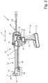
- FIG. 2 A squeezing device 10 is shown in isolation, which is used to carry out a Fig. 1 schematically shown process.
- the squeezing device 10 can basically be designed for squeezing single-component and in this case in particular multi-component masses, wherein the masses for example, for filling, gluing or sealing or similar applications in the construction sector.
- the masses are arranged in cartridges that can be brought into operative connection with the dispensing device 10.
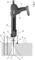
- the squeezing device 10 is designed to interact with a Fig. 5 partially visible cartridge 40, wherein the cartridge device 40 is designed in particular with two chambers, for example film containers, which are connected to one another via a head part.
- a mixer 41 is arranged on the head part, via which the masses in the film containers can be dispensed during a pressing process after they have been mixed with one another.
- the chambers of the cartridge 40 contain masses of a two-component mortar mass, with a hardenable resin component being arranged in a first chamber of the cartridge 40 and a hardener component being arranged in the further chamber of the cartridge 40, which is arranged separately from the first chamber to inhibit the reaction.
- the components are mixed with one another, for example in the area of the mixer 41, with the mass resulting after the mixing of the hardenable resin component and the hardener component being able to be used, for example, as injection mortar for the chemical anchoring of metal elements such as anchor rods in mineral substrates, such as in particular buildings made of brickwork, concrete or natural stone.
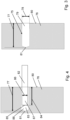
- a hole 75 is made, for example, in a masonry 76, as for example in Fig. 3
- the bore 75 has a borehole depth 77 and a diameter 78, which define an internal volume 79 of the bore 75.
- a surface of the masonry 76 in the area of the bore 75 is designated 80.
- Fig. 4 is shown in simplified form how an element 82, in particular an anchoring means, such as an anchor rod, is arranged in the borehole 75 filled with mortar 83.
- the anchor rod 82 is inserted into the borehole 75 and adjusted in it after the borehole 75 or the borehole 75 has been filled with mortar 83.
- the anchor rod 82 is arranged here in the desired final position with a length 84 in the borehole 75, the length 84 being determined by the distance between the surface 80 of the masonry 76 and a tip 85 of the anchor rod 82.
- a diameter of the anchor rod 82 is designated with 86.
- the dispensing device 10 is designed to dispense the mortar 83 into the bore 75.
- the dispensing device 10 has a receiving space 11 in a housing 12, into which the cartridge 40 can be inserted.
- the housing 12 of the dispensing device 10 extends in the present case essentially along an axial direction A and has a functional section 14 and a handling section 16.
- the functional section 14 essentially has the receiving space 11 and, at a processing-side distal end 18 of the functional section 14, a processing head 19, in the area of which a head part of the cartridge 40 can be arranged.
- the mixer 41 extends forward in the axial direction A beyond the processing head 19 or the distal end 18.
- the handling section 16 of the housing 12 has a handle 21 and an actuation switch 22 arranged in the area of the handle 21.
- a squeezing device 24 is provided, which in the present case is designed with two squeezing pistons, which are firmly connected to one another in particular via a push rod 29.
- Each squeezing piston has a stamp at its end facing the respective chamber of the cartridge 40.
- a drive device shown here only schematically, designed in particular as an electric motor 30, is provided, by means of which the squeezing pistons can be displaced in the axial direction A.
- the dispensing pistons can be moved together in the direction of the distal end 18 via the push rod 29 which can be driven in a feed direction V by the electric motor 30.
- the electric motor 30 is here driven by a Fig. 2
- the squeezing device 10 is supplied with energy by a power supply shown schematically and designed as a battery 31.
- the squeezing device 10 can also be mains-operated, whereby a plug that can be connected to a power network can be provided.
- the squeezing device 10 also has a Control device 33, which is designed to actuate the electric motor 30 according to a user request by means of the actuation switch 22.
- the electric motor 30 can be set into different operating modes by the control device 33, which can be selected by the user, for example, via a Fig. 6 shown rotary switch 42 can be selected.
- a touch screen device 70 can also be provided, by means of which different operating modes can be selected by the user and via which information about the current operating state, the current charge state of the accumulator 31 or the like can be displayed to the user.
- a distance measuring device 60 is shown schematically, which is arranged in the distal end region 18 of the dispensing device 10.
- the distance measuring device 60 can also be arranged in other regions of the dispensing device 10, for example in the region of the handling section 16.
- the distance measuring device 60 is a laser distance measuring device, whereby the distance measuring device 60 can basically work according to any measuring principle.
- the distance measuring device 60 is coupled to the control device 33.
- a distance 90 between the distance measuring device 60 and a surface, in particular the surface 80 of a masonry 76 in the region of the bore 75 can be measured.
- a sensor 61 is also provided which is coupled to the control device 33, wherein the sensor 61 is designed in particular as a gyro sensor 61. By means of the sensor 61, an orientation, in particular inclination, of the squeezing device 10 can be determined.
- the control device 33 is designed to correct the distance value determined by the distance measuring device 60 based on the inclination value during the respective distance measurement.
- the method according to the invention serves in particular to introduce the best possible amount of mortar into the bore 75, so that after the arrangement of the Element, here the anchor rod 82, there is a sufficiently large amount of mortar in the bore 75 to ensure the desired hold of the anchor rod 82. On the other hand, it should be prevented that too much mortar mass is filled into the bore 75, so that after the anchor rod 82 is arranged, mortar mass runs out of the bore 75.
- FIG. 1 An embodiment of a method according to the invention for operating the squeezing device 10 is shown in Fig. 1 shown and is described below.
- step S1 the borehole depth 77 is determined using the distance measuring device 60.
- a distance measurement is carried out when a tip 43 of the mixer 41 is in contact with a bottom 81 of the borehole 75. This measurement is carried out upon request from the user and results in a current distance value 93.
- a reference distance value 92 is stored in a memory device 72 of the control device 33, which corresponds to a distance value when in contact with the surface 80 of the masonry 76 in the area of the bore 75. It can be provided that the reference distance value is assigned to a standard mixer, which is usually used with cartridges 40 used for the dispensing device 10.
- the reference distance value can be measured by means of the distance measuring device 60 upon request from the user.
- a distance measurement is carried out upon request from the user, in particular when the tip 43 of the mixer 41 or of an attachment for a mixer is in contact with the surface 80 of the masonry 76.
- the reference distance value stored in the storage device 72 is overwritten by the reference distance value measured here and used for future methods.
- the borehole depth 77 is calculated by the control device 33 by a difference of the reference distance value 92 from the distance value 93.
- the respective measurement is carried out twice, three times or more times and the respective value is determined as the average of the measurements.
- a diameter 78 of the bore 75 is determined or set. It can be provided that the distance measuring device 60 is designed to determine the diameter 78 of the bore 75. Alternatively, it can also be provided that the diameter 78 of the bore 75 can be set by the user or a value stored in the storage device 72 is used for the diameter 78.
- control device 33 calculates the internal volume 79 of the bore 75 from the borehole depth 77 and the diameter 78 of the bore 75.
- the volume 87 of the anchor rod 82 located within the bore 75 is determined or set.
- a diameter used and an insertion depth or the length 84 are deduced based on the determined or set diameter 78 of the bore 75 and a look-up table stored in the storage device 72.
- these values can be entered by the user.
- a type of element in particular the anchor rod 82
- the volume of the element 82 to be arranged within the bore 75 is deduced based on a look-up table stored in the storage device 72 based on the entered type of element 82 in combination with its diameter and length.
- control device 33 subtracts the volume 87 of the element 82 determined or set in method step S4 from the internal volume 79 of the bore 75 to form a filling volume 88.
- the filling volume 88 determined in method step S5 is set by the control device 33 in method step S6 for the output of a subsequent pressing process, so that in the subsequent pressing process, when the user actuates the actuation switch 22, an amount of mortar corresponding to the determined filling volume 88 is dispensed into the bore 75.
- a predefined absolute or percentage value is deducted from the determined filling volume 88 in order to reliably prevent mass or mortar 83 from running out when the bore 75 in which the element 82 is arranged is filled.
- a speed is determined based on a continuous distance measurement by the distance measuring device 60, by means of which the pressing device 10 is moved relative to the surface 80 of the masonry 76 and thus the tip 43 of the mixer 41 is moved out of the bore 75. It can be provided that an output mass flow is controlled or regulated according to the determined speed using an algorithm stored in the storage device 72 or a stored look-up table. This can, for example, prevent the mixer tip from becoming dirty if the speed is too low and insufficient filling of the bore 75, particularly in the area of the base 81, if the speed is too high.
- an output mass flow is reduced or stopped if a stored limit speed is undershot.
- the user is shown a current speed in relation to an optimal speed by means of the display device 70, for example by means of a bar. For example, a green, a yellow and a red area can be provided.
- an output device can be provided which gives the user optical, acoustic, haptic or similar feedback when a determined speed is greater and/or less than stored limit values.
Landscapes
- Engineering & Computer Science (AREA)
- Mechanical Engineering (AREA)
- Coating Apparatus (AREA)
Priority Applications (3)
| Application Number | Priority Date | Filing Date | Title |
|---|---|---|---|
| EP23181993.9A EP4484020A1 (fr) | 2023-06-28 | 2023-06-28 | Procédé de fonctionnement d'un appareil d'extrusion et appareil d'extrusion |
| PCT/EP2024/066235 WO2025002814A1 (fr) | 2023-06-28 | 2024-06-12 | Procédé de fonctionnement d'un appareil de distribution, et appareil de distribution |
| EP24732676.2A EP4735184A1 (fr) | 2023-06-28 | 2024-06-12 | Procédé de fonctionnement d'un appareil de distribution, et appareil de distribution |
Applications Claiming Priority (1)
| Application Number | Priority Date | Filing Date | Title |
|---|---|---|---|
| EP23181993.9A EP4484020A1 (fr) | 2023-06-28 | 2023-06-28 | Procédé de fonctionnement d'un appareil d'extrusion et appareil d'extrusion |
Publications (1)
| Publication Number | Publication Date |
|---|---|
| EP4484020A1 true EP4484020A1 (fr) | 2025-01-01 |
Family
ID=87036557
Family Applications (2)
| Application Number | Title | Priority Date | Filing Date |
|---|---|---|---|
| EP23181993.9A Withdrawn EP4484020A1 (fr) | 2023-06-28 | 2023-06-28 | Procédé de fonctionnement d'un appareil d'extrusion et appareil d'extrusion |
| EP24732676.2A Pending EP4735184A1 (fr) | 2023-06-28 | 2024-06-12 | Procédé de fonctionnement d'un appareil de distribution, et appareil de distribution |
Family Applications After (1)
| Application Number | Title | Priority Date | Filing Date |
|---|---|---|---|
| EP24732676.2A Pending EP4735184A1 (fr) | 2023-06-28 | 2024-06-12 | Procédé de fonctionnement d'un appareil de distribution, et appareil de distribution |
Country Status (2)
| Country | Link |
|---|---|
| EP (2) | EP4484020A1 (fr) |
| WO (1) | WO2025002814A1 (fr) |
Citations (2)
| Publication number | Priority date | Publication date | Assignee | Title |
|---|---|---|---|---|
| EP0054156A1 (fr) * | 1980-12-16 | 1982-06-23 | HILTI Aktiengesellschaft | Dispositif pour remplir des trous obtenus par perçage |
| US20180111297A1 (en) * | 2015-04-20 | 2018-04-26 | Illinois Tool Works Inc. | Portable tool |
-
2023
- 2023-06-28 EP EP23181993.9A patent/EP4484020A1/fr not_active Withdrawn
-
2024
- 2024-06-12 WO PCT/EP2024/066235 patent/WO2025002814A1/fr not_active Ceased
- 2024-06-12 EP EP24732676.2A patent/EP4735184A1/fr active Pending
Patent Citations (2)
| Publication number | Priority date | Publication date | Assignee | Title |
|---|---|---|---|---|
| EP0054156A1 (fr) * | 1980-12-16 | 1982-06-23 | HILTI Aktiengesellschaft | Dispositif pour remplir des trous obtenus par perçage |
| US20180111297A1 (en) * | 2015-04-20 | 2018-04-26 | Illinois Tool Works Inc. | Portable tool |
Also Published As
| Publication number | Publication date |
|---|---|
| EP4735184A1 (fr) | 2026-05-06 |
| WO2025002814A1 (fr) | 2025-01-02 |
Similar Documents
| Publication | Publication Date | Title |
|---|---|---|
| EP1878500B1 (fr) | Utilisation d'un dispositif de dosage électronique destiné au dosage de liquides | |
| DE102011081137B4 (de) | Ausgabesystem | |
| EP2314384B1 (fr) | Dispositif de compression | |
| EP1004353A1 (fr) | Dispositif pour mélanger et pour l'application dosée des masses à écoulement libre à plusieurs composants | |
| DE19951504A1 (de) | Mischvorrichtung und -verfahren | |
| WO2013092927A1 (fr) | Dispositif d'entraînement d'un doseur-mélangeur | |
| EP2465642A2 (fr) | Appareil de fixation de boulons et procédé de fonctionnement d'un appareil de fixation de boulons | |
| DE202007002792U1 (de) | Vorrichtung zum Vermischen einer Binder- und einer Härter-Komponente zur Herstellung einer gebrauchsfertigen Spachtelmasse | |
| EP2826722A1 (fr) | Appareil de dosage manuel pour des poudres et des pâtes | |
| EP3894095A1 (fr) | Procédé pour faire fonctionner un système de distribution par pression et système de distribution par pression | |
| DE19708548A1 (de) | Mehrkammerschlauchfolienkartusche | |
| EP4735184A1 (fr) | Procédé de fonctionnement d'un appareil de distribution, et appareil de distribution | |
| EP0312776B1 (fr) | Procédé de fixation de tiges d'ancrage | |
| DE102008055179A1 (de) | Farbmischvorrichtung | |
| WO2011006996A1 (fr) | Système de distribution permettant la distribution de matériaux liquides ou pâteux | |
| DE102005026049A1 (de) | Verfahren zum Auftragen einer pastösen Masse | |
| DE102011003127A1 (de) | Befestigungsset und Verfahren zur Befestigung eines Bauteils an einem Untergrund | |
| EP3108147A1 (fr) | Dispositif servant à l'introduction d'une matière de fixation dans une ouverture | |
| DE2432609B2 (de) | Verfahren zum Zuführen der erforderlichen Zusatzwassermenge bei der Herstellung von Beton | |
| EP0324921A2 (fr) | Réservoir pour l'injection d'un mortier composite | |
| DE10257414B4 (de) | Handdispenser mit elektromotorischem Antrieb | |
| DE102010012466B4 (de) | Dosiervorrichtung für einen scherempfindlichen Klebstoff sowie Vorrichtung zur Aufbringung von Klebstoff mit einer derartigen Dosiervorrichtung | |
| DE102021121588A1 (de) | Vorrichtung zum exakten Dosieren eines Fluides, Dosiersystem sowie Verfahren zum exakten Dosieren eines Fluides | |
| EP0244583B1 (fr) | Cartouche à injection remplie d'au moins deux composantes séparées formant ensemble un liant durcissable | |
| DE102008001904A1 (de) | Setzverfahren zum Verankern eines Befestigungselementes |
Legal Events
| Date | Code | Title | Description |
|---|---|---|---|
| PUAI | Public reference made under article 153(3) epc to a published international application that has entered the european phase |
Free format text: ORIGINAL CODE: 0009012 |
|
| STAA | Information on the status of an ep patent application or granted ep patent |
Free format text: STATUS: THE APPLICATION HAS BEEN PUBLISHED |
|
| AK | Designated contracting states |
Kind code of ref document: A1 Designated state(s): AL AT BE BG CH CY CZ DE DK EE ES FI FR GB GR HR HU IE IS IT LI LT LU LV MC ME MK MT NL NO PL PT RO RS SE SI SK SM TR |
|
| STAA | Information on the status of an ep patent application or granted ep patent |
Free format text: STATUS: THE APPLICATION IS DEEMED TO BE WITHDRAWN |
|
| 18D | Application deemed to be withdrawn |
Effective date: 20250702 |