EP4484029A1 - Procédé de production d'un corps moulé par estampage à chaud stratifié - Google Patents
Procédé de production d'un corps moulé par estampage à chaud stratifié Download PDFInfo
- Publication number
- EP4484029A1 EP4484029A1 EP23807724.2A EP23807724A EP4484029A1 EP 4484029 A1 EP4484029 A1 EP 4484029A1 EP 23807724 A EP23807724 A EP 23807724A EP 4484029 A1 EP4484029 A1 EP 4484029A1
- Authority
- EP
- European Patent Office
- Prior art keywords
- steel sheet
- plated steel
- overlapped
- based plated
- heating
- Prior art date
- Legal status (The legal status is an assumption and is not a legal conclusion. Google has not performed a legal analysis and makes no representation as to the accuracy of the status listed.)
- Pending
Links
Images


Classifications
-
- B—PERFORMING OPERATIONS; TRANSPORTING
- B32—LAYERED PRODUCTS
- B32B—LAYERED PRODUCTS, i.e. PRODUCTS BUILT-UP OF STRATA OF FLAT OR NON-FLAT, e.g. CELLULAR OR HONEYCOMB, FORM
- B32B15/00—Layered products comprising a layer of metal
- B32B15/01—Layered products comprising a layer of metal all layers being exclusively metallic
- B32B15/012—Layered products comprising a layer of metal all layers being exclusively metallic one layer being formed of an iron alloy or steel, another layer being formed of aluminium or an aluminium alloy
-
- B—PERFORMING OPERATIONS; TRANSPORTING
- B21—MECHANICAL METAL-WORKING WITHOUT ESSENTIALLY REMOVING MATERIAL; PUNCHING METAL
- B21D—WORKING OR PROCESSING OF SHEET METAL OR METAL TUBES, RODS OR PROFILES WITHOUT ESSENTIALLY REMOVING MATERIAL; PUNCHING METAL
- B21D22/00—Shaping without cutting, by stamping, spinning, or deep-drawing
- B21D22/02—Stamping using rigid devices or tools
- B21D22/022—Stamping using rigid devices or tools by heating the blank or stamping associated with heat treatment
-
- B—PERFORMING OPERATIONS; TRANSPORTING
- B21—MECHANICAL METAL-WORKING WITHOUT ESSENTIALLY REMOVING MATERIAL; PUNCHING METAL
- B21D—WORKING OR PROCESSING OF SHEET METAL OR METAL TUBES, RODS OR PROFILES WITHOUT ESSENTIALLY REMOVING MATERIAL; PUNCHING METAL
- B21D24/00—Special deep-drawing arrangements in, or in connection with, presses
-
- C—CHEMISTRY; METALLURGY
- C09—DYES; PAINTS; POLISHES; NATURAL RESINS; ADHESIVES; COMPOSITIONS NOT OTHERWISE PROVIDED FOR; APPLICATIONS OF MATERIALS NOT OTHERWISE PROVIDED FOR
- C09D—COATING COMPOSITIONS, e.g. PAINTS, VARNISHES OR LACQUERS; FILLING PASTES; CHEMICAL PAINT OR INK REMOVERS; INKS; CORRECTING FLUIDS; WOODSTAINS; PASTES OR SOLIDS FOR COLOURING OR PRINTING; USE OF MATERIALS THEREFOR
- C09D7/00—Features of coating compositions, not provided for in group C09D5/00; Processes for incorporating ingredients in coating compositions
- C09D7/40—Additives
- C09D7/60—Additives non-macromolecular
- C09D7/61—Additives non-macromolecular inorganic
-
- C—CHEMISTRY; METALLURGY
- C21—METALLURGY OF IRON
- C21D—MODIFYING THE PHYSICAL STRUCTURE OF FERROUS METALS; GENERAL DEVICES FOR HEAT TREATMENT OF FERROUS OR NON-FERROUS METALS OR ALLOYS; MAKING METAL MALLEABLE, e.g. BY DECARBURISATION OR TEMPERING
- C21D1/00—General methods or devices for heat treatment, e.g. annealing, hardening, quenching or tempering
- C21D1/18—Hardening; Quenching with or without subsequent tempering
-
- C—CHEMISTRY; METALLURGY
- C21—METALLURGY OF IRON
- C21D—MODIFYING THE PHYSICAL STRUCTURE OF FERROUS METALS; GENERAL DEVICES FOR HEAT TREATMENT OF FERROUS OR NON-FERROUS METALS OR ALLOYS; MAKING METAL MALLEABLE, e.g. BY DECARBURISATION OR TEMPERING
- C21D1/00—General methods or devices for heat treatment, e.g. annealing, hardening, quenching or tempering
- C21D1/68—Temporary coatings or embedding materials applied before or during heat treatment
- C21D1/70—Temporary coatings or embedding materials applied before or during heat treatment while heating or quenching
-
- C—CHEMISTRY; METALLURGY
- C21—METALLURGY OF IRON
- C21D—MODIFYING THE PHYSICAL STRUCTURE OF FERROUS METALS; GENERAL DEVICES FOR HEAT TREATMENT OF FERROUS OR NON-FERROUS METALS OR ALLOYS; MAKING METAL MALLEABLE, e.g. BY DECARBURISATION OR TEMPERING
- C21D8/00—Modifying the physical properties of ferrous metals or ferrous alloys by deformation combined with, or followed by, heat treatment
-
- C—CHEMISTRY; METALLURGY
- C21—METALLURGY OF IRON
- C21D—MODIFYING THE PHYSICAL STRUCTURE OF FERROUS METALS; GENERAL DEVICES FOR HEAT TREATMENT OF FERROUS OR NON-FERROUS METALS OR ALLOYS; MAKING METAL MALLEABLE, e.g. BY DECARBURISATION OR TEMPERING
- C21D9/00—Heat treatment, e.g. annealing, hardening, quenching or tempering, adapted for particular articles; Furnaces therefor
- C21D9/0068—Heat treatment, e.g. annealing, hardening, quenching or tempering, adapted for particular articles; Furnaces therefor for particular articles not mentioned below
-
- C—CHEMISTRY; METALLURGY
- C21—METALLURGY OF IRON
- C21D—MODIFYING THE PHYSICAL STRUCTURE OF FERROUS METALS; GENERAL DEVICES FOR HEAT TREATMENT OF FERROUS OR NON-FERROUS METALS OR ALLOYS; MAKING METAL MALLEABLE, e.g. BY DECARBURISATION OR TEMPERING
- C21D9/00—Heat treatment, e.g. annealing, hardening, quenching or tempering, adapted for particular articles; Furnaces therefor
- C21D9/46—Heat treatment, e.g. annealing, hardening, quenching or tempering, adapted for particular articles; Furnaces therefor for sheet metals
-
- C—CHEMISTRY; METALLURGY
- C21—METALLURGY OF IRON
- C21D—MODIFYING THE PHYSICAL STRUCTURE OF FERROUS METALS; GENERAL DEVICES FOR HEAT TREATMENT OF FERROUS OR NON-FERROUS METALS OR ALLOYS; MAKING METAL MALLEABLE, e.g. BY DECARBURISATION OR TEMPERING
- C21D9/00—Heat treatment, e.g. annealing, hardening, quenching or tempering, adapted for particular articles; Furnaces therefor
- C21D9/46—Heat treatment, e.g. annealing, hardening, quenching or tempering, adapted for particular articles; Furnaces therefor for sheet metals
- C21D9/48—Heat treatment, e.g. annealing, hardening, quenching or tempering, adapted for particular articles; Furnaces therefor for sheet metals deep-drawing sheets
-
- C—CHEMISTRY; METALLURGY
- C22—METALLURGY; FERROUS OR NON-FERROUS ALLOYS; TREATMENT OF ALLOYS OR NON-FERROUS METALS
- C22C—ALLOYS
- C22C21/00—Alloys based on aluminium
- C22C21/02—Alloys based on aluminium with silicon as the next major constituent
-
- C—CHEMISTRY; METALLURGY
- C22—METALLURGY; FERROUS OR NON-FERROUS ALLOYS; TREATMENT OF ALLOYS OR NON-FERROUS METALS
- C22C—ALLOYS
- C22C38/00—Ferrous alloys, e.g. steel alloys
- C22C38/60—Ferrous alloys, e.g. steel alloys containing lead, selenium, tellurium, or antimony, or more than 0.04% by weight of sulfur
-
- C—CHEMISTRY; METALLURGY
- C23—COATING METALLIC MATERIAL; COATING MATERIAL WITH METALLIC MATERIAL; CHEMICAL SURFACE TREATMENT; DIFFUSION TREATMENT OF METALLIC MATERIAL; COATING BY VACUUM EVAPORATION, BY SPUTTERING, BY ION IMPLANTATION OR BY CHEMICAL VAPOUR DEPOSITION, IN GENERAL; INHIBITING CORROSION OF METALLIC MATERIAL OR INCRUSTATION IN GENERAL
- C23C—COATING METALLIC MATERIAL; COATING MATERIAL WITH METALLIC MATERIAL; SURFACE TREATMENT OF METALLIC MATERIAL BY DIFFUSION INTO THE SURFACE, BY CHEMICAL CONVERSION OR SUBSTITUTION; COATING BY VACUUM EVAPORATION, BY SPUTTERING, BY ION IMPLANTATION OR BY CHEMICAL VAPOUR DEPOSITION, IN GENERAL
- C23C2/00—Hot-dipping or immersion processes for applying the coating material in the molten state without affecting the shape; Apparatus therefor
- C23C2/04—Hot-dipping or immersion processes for applying the coating material in the molten state without affecting the shape; Apparatus therefor characterised by the coating material
- C23C2/12—Aluminium or alloys based thereon
-
- C—CHEMISTRY; METALLURGY
- C23—COATING METALLIC MATERIAL; COATING MATERIAL WITH METALLIC MATERIAL; CHEMICAL SURFACE TREATMENT; DIFFUSION TREATMENT OF METALLIC MATERIAL; COATING BY VACUUM EVAPORATION, BY SPUTTERING, BY ION IMPLANTATION OR BY CHEMICAL VAPOUR DEPOSITION, IN GENERAL; INHIBITING CORROSION OF METALLIC MATERIAL OR INCRUSTATION IN GENERAL
- C23C—COATING METALLIC MATERIAL; COATING MATERIAL WITH METALLIC MATERIAL; SURFACE TREATMENT OF METALLIC MATERIAL BY DIFFUSION INTO THE SURFACE, BY CHEMICAL CONVERSION OR SUBSTITUTION; COATING BY VACUUM EVAPORATION, BY SPUTTERING, BY ION IMPLANTATION OR BY CHEMICAL VAPOUR DEPOSITION, IN GENERAL
- C23C2/00—Hot-dipping or immersion processes for applying the coating material in the molten state without affecting the shape; Apparatus therefor
- C23C2/26—After-treatment
-
- C—CHEMISTRY; METALLURGY
- C23—COATING METALLIC MATERIAL; COATING MATERIAL WITH METALLIC MATERIAL; CHEMICAL SURFACE TREATMENT; DIFFUSION TREATMENT OF METALLIC MATERIAL; COATING BY VACUUM EVAPORATION, BY SPUTTERING, BY ION IMPLANTATION OR BY CHEMICAL VAPOUR DEPOSITION, IN GENERAL; INHIBITING CORROSION OF METALLIC MATERIAL OR INCRUSTATION IN GENERAL
- C23C—COATING METALLIC MATERIAL; COATING MATERIAL WITH METALLIC MATERIAL; SURFACE TREATMENT OF METALLIC MATERIAL BY DIFFUSION INTO THE SURFACE, BY CHEMICAL CONVERSION OR SUBSTITUTION; COATING BY VACUUM EVAPORATION, BY SPUTTERING, BY ION IMPLANTATION OR BY CHEMICAL VAPOUR DEPOSITION, IN GENERAL
- C23C2/00—Hot-dipping or immersion processes for applying the coating material in the molten state without affecting the shape; Apparatus therefor
- C23C2/34—Hot-dipping or immersion processes for applying the coating material in the molten state without affecting the shape; Apparatus therefor characterised by the shape of the material to be treated
- C23C2/36—Elongated material
- C23C2/40—Plates; Strips
-
- B—PERFORMING OPERATIONS; TRANSPORTING
- B21—MECHANICAL METAL-WORKING WITHOUT ESSENTIALLY REMOVING MATERIAL; PUNCHING METAL
- B21D—WORKING OR PROCESSING OF SHEET METAL OR METAL TUBES, RODS OR PROFILES WITHOUT ESSENTIALLY REMOVING MATERIAL; PUNCHING METAL
- B21D35/00—Combined processes according to or processes combined with methods covered by groups B21D1/00 - B21D31/00
- B21D35/002—Processes combined with methods covered by groups B21D1/00 - B21D31/00
- B21D35/005—Processes combined with methods covered by groups B21D1/00 - B21D31/00 characterized by the material of the blank or the workpiece
- B21D35/007—Layered blanks
-
- C—CHEMISTRY; METALLURGY
- C08—ORGANIC MACROMOLECULAR COMPOUNDS; THEIR PREPARATION OR CHEMICAL WORKING-UP; COMPOSITIONS BASED THEREON
- C08K—Use of inorganic or non-macromolecular organic substances as compounding ingredients
- C08K3/00—Use of inorganic substances as compounding ingredients
- C08K3/02—Elements
- C08K3/04—Carbon
-
- C—CHEMISTRY; METALLURGY
- C21—METALLURGY OF IRON
- C21D—MODIFYING THE PHYSICAL STRUCTURE OF FERROUS METALS; GENERAL DEVICES FOR HEAT TREATMENT OF FERROUS OR NON-FERROUS METALS OR ALLOYS; MAKING METAL MALLEABLE, e.g. BY DECARBURISATION OR TEMPERING
- C21D1/00—General methods or devices for heat treatment, e.g. annealing, hardening, quenching or tempering
- C21D1/62—Quenching devices
- C21D1/673—Quenching devices for die quenching
-
- C—CHEMISTRY; METALLURGY
- C21—METALLURGY OF IRON
- C21D—MODIFYING THE PHYSICAL STRUCTURE OF FERROUS METALS; GENERAL DEVICES FOR HEAT TREATMENT OF FERROUS OR NON-FERROUS METALS OR ALLOYS; MAKING METAL MALLEABLE, e.g. BY DECARBURISATION OR TEMPERING
- C21D2221/00—Treating localised areas of an article
-
- C—CHEMISTRY; METALLURGY
- C21—METALLURGY OF IRON
- C21D—MODIFYING THE PHYSICAL STRUCTURE OF FERROUS METALS; GENERAL DEVICES FOR HEAT TREATMENT OF FERROUS OR NON-FERROUS METALS OR ALLOYS; MAKING METAL MALLEABLE, e.g. BY DECARBURISATION OR TEMPERING
- C21D2251/00—Treating composite or clad material
- C21D2251/04—Welded or brazed overlays
Definitions
- the present invention relates to a method of manufacturing an overlapped hot stamped component.
- a steel sheet that achieves both high strength and high formability has been demanded in the application of steel sheets for an automobile.
- One example corresponding to the steel sheet that achieves both high strength and high formability is a TRIP (Transformation Induced Plasticity) steel using martensite transformation of retained austenite.
- a high-strength steel sheet excellent in formability and having a strength of about 1000 MPa class can be manufactured with the TRIP steel.
- hot stamping also called hot press, hot pressing, die-quenching, press quenching, or the like.
- This hot stamping is a method of manufacturing a part to obtain a material quality of a desired high strength after pressing by heating a steel sheet up to an Ac3 point or higher (for example, 800°C or higher) to make it into austenite and immediately thereafter pressing it in hot working to thereby ensure formability, and rapidly cooling it down to an Ms point or lower (for example, 400°C or lower) by a metal mold during keeping it at a bottom dead center to make the material into martensite to thereby quench it.
- an automobile part excellent also in shape fixability after forming can be obtained.
- an automobile part such as A-pillar reinforce, B-pillar reinforce, bumper reinforce, tunnel reinforce, side sill reinforce, roof reinforce, or floor cross member is required to have a collision resistant property only at a specific site of each automobile part more than a general site except the specific site.
- oxide scales are generated on the surface of an overlapped hot-pressed member to be manufactured due to high-temperature heating accompanying the hot pressing. Therefore, a problem is that there is a need to remove the generated oxide scales, for example, by shot blast processing after the hot pressing or that the corrosion resistance of the manufactured overlapped hot-pressed member is likely to decrease.
- a problem peculiar to the case of using the non-plated steel sheets as a raw material of the overlapped blank is that a non-overlapped portion (also called “one-sheet part” below) can be subjected to the shot blast processing but removal of the oxide scales formed between the steel sheets at an overlapped portion (also called “overlapped part” below) by the shot blast processing is difficult, and particularly the corrosion resistance is likely to decrease.
- the need to perform the shot blast processing on the overlapped hot-pressed member after the hot pressing is eliminated.
- the plated steel sheet used for hot pressing include a Zn-based plated steel sheet and an Al-based plated steel sheet. Regarding both of Zn-based plating and Al-based plating, the Zn-based plating becomes Zn-Fe-based plating and the Al-based plating becomes Al-Fe-based plating after hot stamping heating by the alloying reaction of Fe diffusing into the plating.
- a Zn-based plated steel sheet namely, a plated steel sheet containing 50 mass% or more of Zn (Zn plating or Zn-based alloy plating of a Zn-Fe alloy, a Zn-Ni alloy, or a Zn-Fe-Al alloy)
- Zn plating or Zn-based alloy plating of a Zn-Fe alloy, a Zn-Ni alloy, or a Zn-Fe-Al alloy suppresses the generation of the oxide scales to eliminate the problem of the need for the shot blast processing.
- the Zn-based plated steel sheet as a raw material of the overlapped blank and performing bending on the overlapped part during the hot stamping, cracks occur in a base iron to cause a problem in the collision resistant property in some cases.
- the bending is a means for ensuring the collision resistant property in terms of a shape, and performing the bending on the overlapped part is a very important using method of the overlapped component.
- general examples of the measure for the liquid-metal embrittlement employed in the case of using the Zn-based plated steel sheet as the hot stamp include a measure of increasing the melting point of the plating by promoting the Zn-Fe alloying reaction during the hot stamping heating and a measure of waiting for solidification of zinc by reducing the forming temperature during the bending of the hot stamping.
- a problem peculiar to the case of using the zinc-based plated steel sheet as a raw material of the overlapped blank is a problem that the overlapped part is larger in sheet thickness than the one-sheet part and therefore has a slow temperature increasing rate and it is difficult to promote the Zn-Fe alloying reaction during the hot stamping heating.
- the cooling rate is also slow, and there is also a problem of the one-sheet part early cooling when waiting for the overlapped part to cool, failing to ensure the martensite structure.
- Zn becomes a film of zinc oxide to suppress the evaporation of Zn at the one-sheet part, but deficiency of oxygen occurs in an atmosphere between the steel sheets at the overlapped part and therefore Zn evaporates, resulting in that the problems in a decrease in corrosion resistance and in liquid-metal embrittlement at the overlapped part become more serious.
- Such an Al-based plated steel sheet as disclosed in Patent Document 4 namely, a plated steel sheet containing 50 mass% or more of Al (Al plating or Al-based alloy plating of an Al-Si alloy or an Al-Fe-Si alloy)) suppresses the generation of the oxide scales as with Zn to eliminate the problem of the need for the shot blast processing and further causes no problem in the liquid-metal embrittlement with Al, which has a higher melting point than Zn.
- the Al-based plated steel sheet is suitable for use as a raw material of the overlapped blank.
- the Al-Fe alloying reaction in the plating of the Al-based plated steel sheet that progresses by the hot stamping heating is important for the spot weldability of the plating.
- the heating time for hot stamping is prolonged, the one-sheet part of the steel sheet is heated for an excessive amount of time, and thus the Al-Fe alloying reaction progresses and an Al-Fe-based alloy plated layer with a high Fe concentration is formed.
- the spot weldability decreases at the one-sheet part of the steel sheet.
- Patent Document 8 There has been still room for improvement also in the techniques described in Patent Document 5 to Patent Document 8 described above regarding the problems of the productivity of parts of hot stamping and the spot weldability at the one-sheet part.
- heating during hot stamping has been performed by controlling the heating time. More specifically, for example, in a preliminary test or the like, the temperature increasing rate or the temperature increasing time of the overlapped part has been confirmed. Then, after taking into account variations in the obtained findings regarding the temperature increasing rate or the temperature increasing time, or another factor, heating during hot stamping has been performed with a relatively long holding time such as 10 minutes, for example. Even in such a case, there has been still room for improvement regarding the problem of spot weldability of the one-sheet part as described above.
- an object of the present invention is to provide a method of manufacturing an overlapped hot stamped component that is capable of improving both the slow temperature increasing rate of an overlapped part and the one-sheet part being heated for an excessive amount of time when an Al-based plated steel sheet is used as a raw material.
- the present inventors conducted a diligent study repeatedly to solve the above problems and focused on lightness L* defined in JIS Z 8781-4: 2013 for the surface of an Al-based plated steel sheet, and consequently found that lower lightness increases the temperature increasing rate of hot stamping heating of the Al-based plated steel sheet. This is thought to be because a lower value of the lightness suggests that the surface of the Al-based plated steel sheet is blackened, and thus characteristics that easily absorb heat are obtained.
- the sheet thickness namely, the total of the thicknesses of the two steel sheets
- the Al-based plated steel sheet makes it possible to obtain high lightness due to the surface having a silver-gray metallic luster. In particular, they found that there is a maximum heating time depending on the lightness L* of the one-sheet part, the sheet thickness, and the heating temperature for preventing the one-sheet part from being heated excessively
- the gist of the present invention completed based on the above-described findings is as follows.
- the Al-based plated steel sheet is used as a raw material of the overlapped blank for hot stamping, it is possible to improve both the slow temperature increasing rate of the overlapped part and the one-sheet part being heated for an excessive amount of time, and to solve the problems of the part productivity of the hot stamped component and the spot weldability of the one-sheet part.
- FIG. 1 is an explanatory view schematically illustrating one example of a method of manufacturing an overlapped hot stamped component according to an embodiment of the present invention.
- an overlapped blank for hot stamping is used as a raw material of the overlapped hot stamped component.
- the overlapped blank for hot stamping according to this embodiment is a type of tailored blank, and is also called a patch work blank.
- an overlapped blank for hot stamping 4 is composed of a first Al-based plated steel sheet 1 and a second Al-based plated steel sheet 2 smaller in area than the first Al-based plated steel sheet 1 by welding 3 them.
- a portion of the overlapped blank for hot stamping 4 where the second Al-based plated steel sheet 2 is overlapped is called an overlapped part 4a, and a non-overlapped portion is called a one-sheet part 4b.
- the second Al-based plated steel sheet 2 is preferably arranged inside relative to an outer edge portion of the first Al-based plated steel sheet 1 so as to prevent a portion of the second Al-based plated steel sheet 2 protruding from the first Al-based plated steel sheet 1 from existing as schematically illustrated in FIG. 1 .
- an Al-based plated layer is applied to both faces of a face 1a on the side in contact with the second Al-based plated steel sheet 2 and a face 1b on the side not in contact with the second Al-based plated steel sheet 2, and also on the second Al-based plated steel sheet 2, an Al-based plated layer is applied to both faces of a face 2a on the side in contact with the first Al-based plated steel sheet 1 and a face 2b on the side not in contact with the first Al-based plated steel sheet 1.
- a carbon-based black coating (not illustrated) is provided at an upper layer of the Al-based plated layer.
- the Al-based plated layer is applied to both faces of the face 1a on the side in contact with the second Al-based plated steel sheet 2 and the face 1b on the side not in contact with the second Al-based plated steel sheet 2, and also on the second Al-based plated steel sheet 2, the Al-based plated layer is applied to both faces of the face 2a on the side in contact with the first Al-based plated steel sheet 1 and the face 2b on the side not in contact with the first Al-based plated steel sheet 1.
- a carbon-based black coating (not illustrated) is provided at an upper layer of the Al-based plated layer
- a carbon-based black coating (not illustrated) is provided at an upper layer of the Al-based plated layer
- the steel sheets are heated up to an Ac3 point or higher in a heating furnace 5, to thereby be made into austenite, and are press-molded and quenched by a metal mold 6 immediately after taken out of the furnace, and thereby the steel sheets are transformed into martensite.
- the overlapped blank for hot stamping 4 becomes an overlapped hot stamped component 12 according to this embodiment excellent in collision resistant property.
- at at least a portion of the overlapped part 4a there exists a portion that becomes a bent part 8 when the overlapped blank for hot stamping 4 becomes the overlapped hot stamped component 12, which is preferable from the viewpoint of improving the collision property of the part of the hot stamped component.
- FIG. 1 a formed product using a hat-shaped metal mold is illustrated as an example of the overlapped hot stamped component 12, and names of sites of the hot stamped component 12 are a head top part 7, the bent part 8 of the head top part, a vertical wall part 10, a flange part 11, and a bent part 9 of the flange part.
- the second Al-based plated steel sheet 2 according to this embodiment is arranged on the outer side of the head top part 7 side in FIG. 1 , the object of the present invention can be achieved even by arranging the second Al-based plated steel sheet 2 on the inner side of the head top part 7.
- the overlapped blank for hot stamping 4 includes the first Al-based plated steel sheet 1 and the second Al-based plated steel sheet 2 welded to the first Al-based plated steel sheet 1 and smaller in area than the first Al-based plated steel sheet 1, in which Al-based plating is applied to both faces of each of the first Al-based plated steel sheet 1 and the second Al-based plated steel sheet 2.
- the first Al-based plated steel sheet 1 and the second Al-based plated steel sheet 2 according to this embodiment are Al-based plated steel sheets each including Al-based plated layers on both surfaces of a base material steel sheet.
- the chemical composition of the base material steel sheet in each of the first Al-based plated steel sheet 1 and the second Al-based plated steel sheet 2 is not particularly limited.
- a tensile strength of 1500 MPa or more about 400 or more in Vickers hardness (namely, HV1 in JIS Z2244-1: 2020) when a test force is set to 9.8107 N
- a base material steel sheet having a chemical composition composed of, by mass%, C: 0.19 to 0.50%, Si: 0.01 to 1.50%, Mn: 0.4 to 2.0%, Cr: 0.01 to 1.00%, Ti: 0.001 to 0.100%, B: 0.0005 to 0.0100%, P: 0.100% or less, S: 0.100% or less, Al: 0 to 1.000%, N: 0 to 0.0100%, Nb: 0 to 0.100%, Mo, Ni, Cu, Co, W, Sn, V,
- the method of manufacturing the Al-based plated steel sheet using the above-described chemical composition for the base material steel sheet is not limited in particular.
- the one manufactured through a conventional pig iron-making process and steel-making process and by processes of hot rolling, pickling, cold rolling, and Sendzimir hot-dip aluminum plating can be used.
- a sheet thickness d1 (mm) of the first Al-based plated steel sheet 1 and a sheet thickness d2 (mm) of the second Al-based plated steel sheet 2 are each preferably 0.5 mm or more and 3.2 mm or less selectively. Setting the sheet thickness to 0.5 mm or more makes it possible to maintain the productivity in the processes of hot rolling and cold rolling at a desired state. Further, setting the sheet thickness to 3.2 mm or less makes it possible to prevent a phenomenon in which the cooling rate decreases during metal mold quenching of hot stamping and hardenability becomes insufficient, to thus fail to obtain a desired tensile strength.
- the sheet thickness d1 of the first Al-based plated steel sheet 1 and the sheet thickness d2 of the second Al-based plated steel sheet 2 can be measured using, for example, a micrometer based on JIS B7502: 2016. Further, the above-described sheet thicknesses d1 and d2 are each set to a sheet thickness including the thicknesses of the Al-based plated layers provided on both faces of the base material steel sheet, in addition to the sheet thickness of the base material steel sheet.
- An increase in the total sheet thickness slows down the temperature increasing rate of the overlapped part to reduce productivity during hot stamping heating. Therefore, the total sheet thickness d is set to 4.8 mm or less.
- d satisfies Expression (c) below. 2.5 ⁇ d ⁇ 4.8
- the total sheet thickness d is preferably 4.6 mm or less, more preferably 4.4 mm or less, 4.2 mm or less, or 4.0 mm or less.
- a decrease in the total sheet thickness not only leads to saturation of the effect of improving the temperature increasing rate, but also leads to a decrease in the collision property of the hot stamped component. Therefore, the total sheet thickness d is set to 2.5 mm or more.
- the total sheet thickness d is preferably 2.8 mm or more and more preferably 3.2 mm or more.
- the coating weight of the Al-based plated layer applied to both faces of the first Al-based plated steel sheet 1 is W1a (g/m 2 ) on the surface 1a of the side in contact with the second Al-based plated steel sheet 2, and is W1b (g/m 2 ) on the surface 1b of the side not in contact with the second Al-based plated steel sheet 2.
- the coating weight of the Al-based plated layer applied to both faces of the second Al-based plated steel sheet 2 is W2a (g/m 2 ) on the surface 2b of the side not in contact with the first Al-based plated steel sheet 1.
- the values of W1a, W1b, and W2b described above are each independently within a range of 20 g/m 2 or more and 120 g/m 2 or less per face.
- the average coating weight of the Al-based plated layer at the non-overlapped part (one-sheet part 4b) in the overlapped blank for hot stamping 4 is set to W1 (g/m 2 ) per face.
- W1a the coating weight of the Al-based plated layer on one face of the surface on the side in contact with the second Al-based plated steel sheet 2
- W1b the coating weight of the Al-based plated layer on one face of the surface on the side not in contact with the second Al-based plated steel sheet 2
- W1 0.5 ⁇ (W1a + W1b) is established.
- the average coating weight of the Al-based plated layer at the overlapped part 4a in the overlapped blank for hot stamping 4 is set to W2 (g/m 2 ) per face.
- W1b g/m 2
- W2b 0.5 ⁇ (W1b + W2b)
- the surface 1a on the side in contact with the second Al-based plated steel sheet 2 and the surface 1b on the side not in contact with the second Al-based plated steel sheet 2, and in the second Al-based plated steel sheet 2, the surface 2b on the side not in contact with the first Al-based plated steel sheet 1 are faces exposed to a heat source when the manufactured overlapped blank is subjected to hot stamping heating, and become surfaces important for controlling the temperature increasing rate during the heating in the hot stamping.
- the plating coating weight of the Al-based plated layer according to this embodiment is not limited in particular.
- the characteristics required for the hot stamped component the following are cited as preferable characteristics: (a) suppression of generation of Fe scales during hot stamping heating; and (b) suppression of chip or pressing flaw of plating caused by slipping (also called powdering) of plating during hot stamping.
- the powdering occurs due to a compressive stress applied on the plating on the inner face of the bent part made during forming, a shear stress applied on the plating by the sliding from the metal mold during forming, or another cause.
- the coating weight W1 or W2 of the Al-based plated layer on each of the steel sheets is less than 20 g/m 2 , the thickness of the plating is thin, thus causing a problem of insufficient suppression of the Fe scales. Therefore, the coating weight W1 or W2 of the Al-based plated layer on each of the steel sheets is preferably set to 20 g/m 2 or more independently.
- the coating weight W1 or W2 of the Al-based plated layer on each of the steel sheets is more preferably 30 g/m 2 or more independently, and further preferably, in order of increasing preference, 35 g/m 2 or more, 40 g/m 2 or more, 45 g/m 2 or more, or 50 g/m 2 or more.
- the coating weight W1 or W2 of the plating per face on each of the steel sheets is preferably set to 120 g/m 2 or less independently.
- the coating weight W1 or W2 of the plating per face on each of the steel sheets is more preferably 110 g/m 2 or less independently, and further preferably, in order of increasing preference, 100 g/m 2 or less, 95 g/m 2 or less, or 90 g/m 2 or less.
- the coating weight of the Al-based plated layer on the surface of the side in contact with the first Al-based plated steel sheet is not particularly defined.
- W1 - W21 between the coating weights W1 and W2 of the plating per face on each of the steel sheets is preferably 40 g/m 2 or less.
- W1 - W21 is 40 g/m 2 or less, spot weldability can be further improved in the hot stamped component to be manufactured.
- W1 - W21 is more preferably 35 g/m 2 or less, 30 g/m 2 or less, 25 g/m 2 or less, or 20 g/m 2 or less.
- the thickness ( ⁇ m) of the Al-based plated layer on each of the steel sheets can be approximated from the plating coating weight (g/m 2 ), and can be roughly found by Equation (1) below though depending on the chemical composition of the Al-based plated layer.
- Plating thickness Plating coating weight / 3
- FIG. 2 schematically illustrates a layer structure of a plated steel sheet 13 on one face side in which the Al-based plated layer according to this embodiment is provided on the surface of the base material steel sheet.
- Al-based plated layer according to this embodiment is manufactured by the hot-dip plating method, an aluminum-iron-based (Al-Fe-based) alloy layer (not illustrated) is formed near the boundary of an Al-based plated layer 14 with a base material steel sheet 15.
- the base material steel sheet is dipped in a hot-dip aluminum plating bath and subjected to gas wiping in nitrogen or atmosphere, and thereby the Al-based plated steel sheet whose coating weight is adjusted can be manufactured.
- the aluminum-iron-based alloy layer is necessarily formed by elution of Fe during hot-dip plating at the interface between the Al-based plated layer 14 and the base material steel sheet 15 in FIG. 2 .
- the Al-based plated layer 14 in FIG. 2 also includes the aluminum-iron-based alloy layer.
- the chemical composition of the hot-dip aluminum plating bath for forming the above-described Al-based plated layer is not particularly limited (that is, the chemical composition is substantially the same as that of the Al-based plated layer 14 except for Fe).
- the content of Al in the hot-dip aluminum plating bath is preferably 80 mass% or more in terms of being excellent in heat resistance required during hot stamping heating.
- the content of Si in the hot-dip aluminum plating bath is preferably 2 mass% or more in terms of easy control of the thickness of the aluminum-iron-based alloy layer. Setting the content of Si to 2 mass% or more makes it possible to prevent the aluminum-iron-based alloy layer from becoming too thick and reducing formability.
- setting the content of Si in the hot-dip aluminum plating bath to 15 mass% or less makes it possible to prevent the alloying reaction during hot stamping heating from slowing down and reducing the productivity of hot stamping.
- the hot-dip aluminum plating bath contains 2 mass% or more and 15 mass% or less of Si, a eutectic structure of Al and Si is formed in the Al-based plated layer 14 formed by using such a plating bath based on a constitution diagram.
- 1 mass% or more and 5 mass% or less of Fe is inevitably contained in some cases as an eluted component from the base material steel sheet.
- Examples of other inevitable impurities include eluted components in a hot-dip plating facility and elements such as Cr, Mn, Zn, V, Ti, Sn, Ni, Cu, W, Bi, Mg, and Ca due to impurities in an ingot of the hot-dip aluminum plating bath, and these elements are contained by less than 1 mass% in some cases.
- the Al-based plated layer 14 may be a plated layer having a chemical composition (average chemical composition) composed of by mass%, Al: 80 to 97%, Si: 2 to 15%, Fe: 1 to 15%, Cr: 0% or more and less than 1%, Mo: 0% or more and less than 1%, Zn: 0% or more and less than 1%, V: 0% or more and less than 1%, Ti: 0% or more and less than 1%, Sn: 0% or more and less than 1%, Ni: 0% or more and less than 1%, Cu: 0% or more and less than 1%, W: 0% or more and less than 1%, Bi: 0% or more and less than 1%, Mg: 0% or more and less than 1%, Ca: 0% or more and less than 1%, and the balance of impurities.
- a chemical composition average chemical composition
- the hot-dip aluminum plating bath inevitably contains 1 mass% or more and 5 mass% or less of Fe, whereas the aluminum-iron-based alloy layer is formed in the Al-based plated layer, and thus the proportion of Fe increases. Therefore, the chemical composition of the Al-based plated layer 14 may be Fe: 1 to 15%.
- Examples of the metal structure of the above-described aluminum-iron-based alloy layer include a ⁇ phase (FeAl 3 ), a ⁇ phase (Fe 2 Al 5 ), a ⁇ phase (FeAl 2 ), FesAl, and FeAl, which are binary alloys of Al and Fe, an Al solid-solution-based BCC phase ( ⁇ 2, ⁇ ), and so on, and the aluminum-iron-based alloy layer is composed of a combination of those plating phases.
- Examples of the metal structure of the aluminum-iron-based alloy layer in the case of containing Si include a ⁇ 1 phase (Al 2 Fe 3 Si 3 ), a ⁇ 2 phase (Al 3 FeSi), a ⁇ 3 phase (Al 2 FeSi), a ⁇ 4 phase (Al 3 FeSi 2 ), a ⁇ 5 phase (Al 8 Fe 2 Si), a ⁇ 6 phase (Al 9 Fe 2 Si 2 ), a ⁇ 7 phase (Al 3 Fe 2 Si 3 ), a ⁇ 8 phase (Al 2 Fe 3 Si 4 ), a ⁇ 10 phase (Al 4 Fe 1.7 Si), a ⁇ 11 phase (Al 5 Fe 2 Si), and so on, (where each phase does not have a stoichiometric composition in some cases), and the metal structure of the aluminum-iron-based alloy layer is often composed of the ⁇ 5 phase or ⁇ phase mainly.
- the coating weight of the above-described Al-based plated layer per face is measured using the method of JIS G 3314: 2019 JB. 3 (a sodium hydroxide-hexamethylenetetramine-hydrochloric acid peeling gravimetric method) after the Al-based plated layer on one face is protected with a seal beforehand.
- This lightness is the CIE 1976 lightness index L* (CIE 1976 lightness) defined in 3.3 of JIS Z 8781-4: 2013, and is simply referred to as "lightness” or “lightness L*” below.
- L*1 means the average lightness of the surface of the Al-based plated layer at the non-overlapped part (one-sheet part 4b) in the overlapped blank for hot stamping 4.
- a lower value of the lightness increases the temperature increasing rate in heating during hot stamping in the aluminum plated steel sheet. This is thought to be because a lower value of the lightness suggests that the surface of the aluminum plated steel sheet is blackened, and thus characteristics that easily absorb heat are obtained. Conversely, at the one-sheet part, the sheet thickness is thinner than at the overlapped part, and thus the temperature increases quickly, leading to an excessive amount of heating time. For this reason, it is important to increase the lightness at the one-sheet part to suppress heat absorption. That is, it is important to lower the lightness of the surface at the overlapped part having a thick sheet thickness, and conversely, to increase the lightness of the surface at the one-sheet part.
- the Al-based plated steel sheet makes it possible to obtain high lightness due to the surface having a silver-gray metallic luster, and increasing the thickness of the Al-based plated layer, (which can be thought as the coating weight of the Al-based plated layer), makes it possible to suppress the blackening of the plated surface caused by alloying of the plating reaching the surface, resulting in that high lightness can be maintained even during the hot stamping heating.
- using the carbon-based black coating for the upper layer of the Al-based plated steel sheet makes it possible to reduce the lightness.
- the lightness can be adjusted to a desired value.
- L*b is 40 or more and 60 or less
- L*1 is (L*b + 20) or more and 80 or less.
- L*b satisfies Expression (a)
- L*1 satisfies Expression (b).
- L*b is set to 60 or less.
- L*b is preferably 58 or less, more preferably 56 or less, and further preferably 54 or less.
- L*b is set to 40 or more.
- L*b is preferably 42 or more, more preferably 44 or more, and further preferably 46 or more.
- L*1 is set to (L*b + 20) or more.
- L*1 is preferably (L*b + 22) or more, and more preferably (L*b + 24) or more.
- L*1 is set to 80 or less.
- L*1 is preferably 78 or less and more preferably 76 or less.
- L*b is 20 or more and 40 or less
- L*1 is (L*b + 20) or more and 60 or less. That is, L*b satisfies Expression (A), and L*1 satisfies Expression (B). 20 ⁇ L * b ⁇ 40 L * b + 20 ⁇ L * 1 ⁇ 60
- L*b is set to 40 or less.
- L*b is set to 40 or less, and thereby the temperature increasing rate during the hot stamping heating at the overlapped part is further improved.
- the carbon-based black coating is provided at an upper layer of the Al-based plated layer on the side not in contact with the first Al-based plated steel sheet, and in the first Al-based plated steel sheet, the carbon-based black coating is provided at an upper layer of the Al-based plated layer on the side not in contact with the second Al-based plated steel sheet, and thus excessive formation of the thickness of the coating can be suppressed. As a result, it is possible to suppress the generation of spatters in the spot welding 3 when manufacturing the overlapped blank 4 in FIG. 1 .
- L*b is preferably 38 or less, more preferably 36 or less, and further preferably 34 or less.
- L*b is set to 20 or more.
- L*b is preferably 22 or more and more preferably 24 or more.
- L*1 is set to (L*b + 20) or more.
- L*1 is preferably (L*b + 22) or more, and more preferably (L*b + 24) or more.
- L*1 is set to 80 or less.
- L*1 is preferably 78 or less and more preferably 76 or less.
- the lightness can be measured using a spectrophotometric colorimeter (SC-T-GV5 manufactured by Suga Test Instruments Co., Ltd., including specular reflection light) with a measurement beam diameter ⁇ of 15 mm.
- SC-T-GV5 manufactured by Suga Test Instruments Co., Ltd., including specular reflection light
- FIG. 3 schematically illustrates a layer structure of an Al-based plated steel sheet 16 on one face side in which the Al-based plated layer 14 is provided on the surface of the base material steel sheet 15 according to this embodiment, and a carbon-based black coating 17 is further provided at an upper layer of the Al-based plated layer 14.
- the carbon-based black coating 17 is provided at the upper layer of the Al-based plated layer located on the surface 2b of the side not in contact with the first Al-based plated steel sheet 1.
- the Al-based plated steel sheet has a silver-gray metallic luster surface, and thus the lightness is high.
- providing the carbon-based black coating at the upper layer of the Al-based plated steel sheet makes it possible to reduce the lightness.
- the carbon-based black coating 17 is burned off by combustion by the oxidation reaction during heating in hot stamping and then is discharged as CO 2 or the like. As a result, it is possible to suppress the decrease in spot weldability of the overlapped hot stamp molded part caused by the remaining carbon-based black coating 17.
- examples of the means to reduce the lightness without using the carbon-based black coating include a method of performing heating at about 700 to 800°C, thereby alloying the plating to the surface.
- carbides precipitate in the base material steel sheet, and thus the collision property after hot stamping decreases, resulting in that using the one produced by the above-described method as a material of the overlapped blank for hot stamping is not preferable.
- examples of another means to reduce the lightness without using the carbon-based black coating include a method of applying electroplating of Zn, Zn-Ni, Zn-Fe to the upper layer of the Al-based plated layer, and a method of subjecting the Al-based plated steel sheet to an acid pickling treatment.
- both of these methods increase the amount of oxide on the surface of the Al-based plated layer after the hot stamping heating, which leads to the generation of spatters in the spot welding and therefore requires attention.
- the carbon-based black coating at the upper layer of the Al-based plated layer located on the surface 1b of the side not in contact with the second Al-based plated steel sheet 2.
- the lightness is reduced also in the first Al-based plated steel sheet, and thereby the temperature increasing rate of the overlapped part can be further improved.
- no carbon-based black coating should be provided on either the surface located at the surface 2a of the side in contact with the first Al-based plated steel sheet 1 in the second Al-based plated steel sheet 2 or the surface located at the surface 1a of the side in contact with the second Al-based plated steel sheet 2 in the first Al-based plated steel sheet 1.
- the intrusion of oxygen necessary for combustion of the coating is inhibited on the side in contact with the steel sheet, and thus unburned carbon-based black coating remains, which results in a factor that reduces the spot weldability of the hot stamped component.
- examples of the means to further increase the lightness of the Al-based plated steel sheet having a silver-gray metallic luster include heating the Al-based plated steel sheet to about 500 to 600°C and oxidizing its surface, thereby whitening the surface. This makes it possible to further increase the lightness of the surface of the Al-based plated steel sheet.
- the film thickness of such a carbon-based black coating is preferably 0.3 ⁇ m or more and 10 ⁇ m or less.
- the film thickness of the carbon-based black coating is set to 0.3 ⁇ m or more, thereby making it possible to suppress the increase in lightness and increase the temperature increasing rate of the overlapped part.
- the film thickness of the carbon-based black coating is more preferably 0.4 ⁇ m or more, and further preferably, in order of increasing preference, 0.5 ⁇ m or more, 0.6 ⁇ m or more, or 0.7 ⁇ m or more.
- the film thickness of the carbon-based black coating is set to 10 ⁇ m or less, thereby making it possible to reduce the lightness while ensuring economic efficiency, and to ensure spot weldability without leaving the coating after the hot stamping heating. Further, when the film thickness of the carbon-based black coating exceeds 10 ⁇ m, the coating may peel off, which is industrially undesirable due to contamination of a facility and at the same time, may fail to obtain a desired temperature increasing rate after hot stamping heating.
- the film thickness of the carbon-based black coating is more preferably 8 ⁇ m or less, and further preferably, in order of increasing preference, 6 ⁇ m or less, 5 ⁇ m or less, or 4 ⁇ m or less.
- the film thickness of the carbon-based black coating can be found as an average value of the thicknesses of the coatings measured in three fields of view by performing observation of the cross section of the plating under an optical microscope (for example, area: 100 ⁇ m ⁇ 100 ⁇ m) (without etching) and performing measurement of the thickness of the coating at the upper layer of the aluminum plated layer in the three fields of view, as illustrated in FIG. 3 .
- the coating is analyzed from the cross section with an electron probe micro analyzer (EPMA) and the coating with a carbon content of 30 mass% or more is determined to be the carbon-based black coating.
- the coating being a black coating is determined from the fact that the value of the lightness L* from the surface is 60 or less.
- the carbon-based black coating 17 can selectively contain resin as a binder to improve the adhesiveness to the Al-based plated layer.
- the type of resin is not particularly limited, and examples thereof include a polyethylene resin, a polyolefin resin, a polyacrylic resin, a polymethacrylic acid resin, a polyepoxy resin, a polyurethane resin, a polycarbonate resin, and so on.
- the coating weight described here indicates the coating weight of Zn, Ti, Cu, or V per unit area.
- Zn, Ti, Cu, and V are elements that form oxides having good infrared absorption in addition to improving emissivity.
- the carbon-based black coating containing such an element is provided, thereby making it possible to suppress the difference in temperature increasing rate between the overlapped part having a slow temperature increasing rate and the one-sheet part having a fast temperature increasing rate, which is a problem caused when used as an overlapped blank.
- the carbon-based black coating 17 described above is burned off during the hot stamping heating, whereas Zn, Ti, Cu, or V remains even during the hot stamping heating. Therefore, the carbon-based black coating containing such an element can further contribute to improving the temperature increasing rate at high temperatures.
- Zn, Ti, Cu, and V may be contained in either a metal state or an oxide state. This is because they become oxides during the temperature increasing process and contribute to improving emissivity.
- the total coating weight of such elements in the carbon-based black coating is preferably 0.1 g/m 2 or more.
- the total coating weight of such elements in the carbon-based black coating is more preferably 0.2 g/m 2 or more, further preferably 0.3 g/m 2 or more, and still more preferably 0.5 g/m 2 or more.
- the total coating weight of such elements in the carbon-based black coating is set to 3.0 g/m 2 or less, thereby making it possible to exhibit such an effect of suppressing the difference in temperature increasing rate as described above without saturation. Further, Zn, Ti, Cu, and V remain even after the hot stamping heating and the total coating weight of such elements in the carbon-based black coating is set to 3.0 g/m 2 or less, thereby making it possible to maintain the spot weldability of the hot stamped component.
- the total coating weight of such elements in the carbon-based black coating is more preferably 2.5 g/m 2 or less and further preferably 2.0 g/m 2 or less.
- the coating weights (contents) of Zn, Ti, Cu, and V can be found by performing elemental analyses from the surface using, for example, a fluorescent X-ray analysis apparatus (ZSX Primus manufactured by Rigaku Corporation) and quantifying the coating weights of Zn, Ti, Cu, and V
- the method of treating the above-described carbon-based black coating 17 is not particularly limited, but the carbon-based black coating 17 can be manufactured, for example, by preparing an aqueous coating solution in which aqueous dispersion type carbon black (for example, RCF#52 manufactured by Mitsubishi Chemical Corporation), zinc oxide (for example, Nano Tek manufactured by C.I. Kasei Co., Ltd.) or titanium oxide (for example, Nano Tek manufactured by C.I. Kasei Co., Ltd.), copper oxide (for example, Nano Tek manufactured by C.I.
- aqueous dispersion type carbon black for example, RCF#52 manufactured by Mitsubishi Chemical Corporation
- zinc oxide for example, Nano Tek manufactured by C.I. Kasei Co., Ltd.
- titanium oxide for example, Nano Tek manufactured by C.I. Kasei Co., Ltd.
- copper oxide for example, Nano Tek manufactured by C.I.
- the carbon-based black coating 17 can be manufactured by using a method of vacuum deposition of metal of Zn, Ti, Cu, or V on the aluminum plated steel sheet.
- both of the above-described carbon-based black coating 17 and a coating layer 17' containing at least one of Zn, Ti, Cu, and V may be provided on the Al-based plated layer.
- the arrangement order of the carbon-based black coating 17 and the coating layer 17' containing at least one of Zn, Ti, Cu, and V is not particularly limited, but the carbon-based black coating 17 may be located at the upper layer of the coating layer 17' containing at least one of Zn, Ti, Cu, and V, or the coating layer 17' containing at least one of Zn, Ti, Cu, and V may be located at the upper layer of the carbon-based black coating 17.
- Such a carbon-based black coating 17 or coating layer 17' containing at least one of Zn, Ti, Cu, and V may be provided on both faces of the base material steel sheet, and is more preferably provided only on a face of the side exposed to the heat source during the hot stamping heating in the base material steel sheet.
- the type of the welding spot welding, seam welding, braze welding, laser welding, plasma welding, arc welding or the like can be selected.
- the spot welding that can establish contact even at the inside of the overlapped part at a plurality of points and establish a direct bond by applying pressure between the steel sheets is preferable.
- the above-described overlapped blank for hot stamping 4 is heated, and when forming it immediately after such heating, the bent part obtained by bending at least a portion of the overlapped part is provided, thereby manufacturing the overlapped hot stamped component 12 in this embodiment.
- the carbon-based black coating is provided at the surface of the face 2b of the non-overlapped side of the second Al-based plated steel sheet 2 having a smaller area of the overlapped blank in FIG. 1 , thereby making it possible to reduce the lightness and improve the temperature increasing rate.
- the excessive amount of heating time of the one-sheet part whose temperature increases quickly is also shortened, and the alloying reaction of the aluminum plating is suppressed, and the spot weldability of the overlapped hot stamped component improves.
- the times t1 and t2 are determined as the solutions to quadratic equations for the times t1 and t2, as in Equation (d) and Equation (e) below, where t1 is the smaller of the solutions to the quadratic equation in Equation (d) below, and t2 is the smaller of the solutions to the quadratic equation in Equation (e) below.
- Equation (d) ⁇ B 1 ⁇ B 1 2 ⁇ 4 ⁇ A 1 ⁇ C 1 ⁇ T1 0.5 / 2 ⁇ A1
- Equation (e) ⁇ B 2 ⁇ B 2 2 ⁇ 4 ⁇ A 2 ⁇ C 2 ⁇ T1 0.5 / 2 ⁇ A2
- the present inventors performed numerical calculation simulations based on a heat transfer equation in which the temperature is increased by radiation heat and a diffusion model for the plating alloying reaction, while varying the sheet thickness of the steel sheet forming the overlapped blank and taking into account actual operating conditions for the heating process in the hot stamping. From the simulation results, they were able to obtain findings about the temperature increasing time and the formation time of a diffusion layer, and based on the obtained findings, they formulated the conditions that must be satisfied by the heating temperature and the heating time. The results of the formulation are the above-described relational equations.
- the heating time t is less than the aforementioned t1 (minute)
- the heating is not sufficient, and thus the martensitic transformation of the overlapped part after hot pressing is to be insufficient, resulting in that the material hardness decreases and the collision resistant property of the part decreases.
- the heating time t is greater than the aforementioned (t2 + ⁇ t2) (minute)
- the heating of the one-sheet part is to be excessively long, resulting in that the alloying reaction of the aluminum plating progresses excessively and the spot weldability decreases.
- Equation (f) ⁇ t2' ⁇ ⁇ t2 is established, and thus as illustrated in FIG. 7 , as long as the heating time is (t2 + ⁇ t2') or less, the heating time is always (t2 + ⁇ t2) or less. For this reason, as long as the heating time is set to (t2 + ⁇ t2') or less, the calculations related to Equation (f) and the like may be omitted.
- ⁇ t 2 ′ 1.498 ⁇ 10 13 ⁇ e ⁇ 0.03198 ⁇ T1
- controlling the heating time to t1 (minute) (lower limit) or more and t2 + ⁇ t2 (upper limit) or less makes it possible to obtain an overlapped hot stamped component that is excellent in hot stamping productivity and spot weldability.
- the upper limit of the heating time t is set to (t2 + ⁇ t2), and thereby it becomes possible to avoid unnecessary prolongation of the heating time, which has been conventionally determined while ensuring a safety margin based on the results of preliminary tests, or the like, logically determine the upper limit of the heating time t, and further achieve a further improvement in productivity.
- the upper limit of the heating time t is set to (t2 + ⁇ t2), and thereby it becomes possible to suppress the increase in thickness of the diffusion layer also in the hot stamped component to be manufactured, which contributes to improving the spot weldability.
- the carbon-based black coating is provided at the surface of the face 2b of the non-overlapped side of the second Al-based plated steel sheet 2 having a smaller area of the overlapped blank in FIG. 1 , to thereby reduce the lightness, and further, the carbon-based black coating is provided also at the surface of the face 1b of the non-overlapped side of the first Al-based plated steel sheet 1, to thereby reduce the lightness.
- This makes it possible to further improve the temperature increasing rate during the heating in the hot stamping.
- the film thickness of the carbon-based black coating at the above-described face 2b and the film thickness of the carbon-based black coating at the face 1b may be the same or different. At this time, the excessive amount of heating time of the one-sheet part, where the temperature increases quickly, is also shortened, and the alloying reaction of the aluminum plating is also suppressed, and the spot weldability of the overlapped hot stamped component improves.
- the overlapped blank when heating the overlapped blank in a heating furnace at a temperature (atmospheric temperature) T3 (°C) for the time t3 (minute), the overlapped blank is heated for a time of t3 (minute) or more and (t4 + ⁇ t4) (minute) or less, which is calculated by Equation (D) to Equation (F) below, and then, the heated blank is molded by the metal mold, and at the same time, the molded blank is cooled (quenched) by heat removal from the metal mold (if necessary, the metal mold is cooled by cooling water passing through the inside of the metal mold to increase the cooling rate of the molded blank), or other means.
- T3 atmospheric temperature
- the times t3 and t4 are determined as the solutions to quadratic equations for the times t3 and t4, as in Equation (D) and Equation (E) below, where t3 is the smaller of the solutions to the quadratic equation in Equation (D) below, and t4 is the smaller of the solutions to the quadratic equation in Equation (E) below.
- the present inventors performed numerical calculation simulations based on a heat transfer equation in which the temperature is increased by radiation heat and a diffusion model for the plating alloying reaction, while varying the sheet thickness of the steel sheet forming the overlapped blank and taking into account actual operating conditions for the heating process in the hot stamping. From the simulation results, they were able to obtain findings about the temperature increasing time and the formation time of a diffusion layer, and based on the obtained findings, they formulated the conditions that must be satisfied by the heating temperature and the heating time. The results of the formulation are the above-described relational equations.
- the heating time t is less than the aforementioned t3 (minute)
- the heating is not sufficient, and thus the martensitic transformation of the overlapped part after hot pressing is to be insufficient, resulting in that the material hardness decreases and the collision resistant property of the part decreases.
- the heating time t is greater than the aforementioned (t4 + ⁇ t4) (minute)
- the heating of the one-sheet part is to be excessively long, resulting in that the alloying reaction of the aluminum plating progresses excessively and the spot weldability decreases.
- controlling the heating time to t3 (minute) (lower limit) or more and t4 + ⁇ t4 (upper limit) or less makes it possible to obtain a more preferable overlapped hot stamped component that is excellent in hot stamping productivity and spot weldability.
- the upper limit of the heating time t is set to (t4 + ⁇ t4), and thereby it becomes possible to avoid unnecessary prolongation of the heating time, which has been conventionally determined while ensuring a safety margin based on the results of preliminary tests, or the like, logically determine the upper limit of the heating time t, and further achieve a further improvement in productivity.
- the upper limit of the heating time t is set to (t4 + ⁇ t4), and thereby it becomes possible to suppress the increase in thickness of the diffusion layer also in the hot stamped component to be manufactured, which contributes to improving the spot weldability.
- the above-described heating temperature means the maximum ultimate temperature of the steel sheets of the overlapped part.
- the heating method include heating by an electric furnace, a gas furnace, a far-infrared furnace, a near-infrared furnace, and so on, energization heating, high-frequency heating, induction heating, and so on.
- the electric furnace, the gas furnace, and the far-infrared furnace are preferred because the overlapped blank tends to be large in area and a large blank can be heated at a uniform temperature.
- the above-described heating temperature is generally preferably in the temperature range of the Ac3 point (for example, 800°C or 840°C) or higher at which the base material steel sheet is austenitized to 1000°C or lower.
- the heating temperature is more preferably 860°C or higher, and further preferably 880°C or higher, 890°C or higher, or 900°C or higher, in order to improve hardenability by dissolving carbides in the steel sheet and to shorten the heating time (improve productivity).
- the heating temperature is more preferably 950°C or lower, and further preferably 930°C or lower, in terms of the ability to equalize the temperature increasing rate between the overlapped part and the one-sheet part.
- the above-described heating time means the time from the time when the overlapped blank is inserted into the heating furnace to the time when it is extracted from the heating furnace.
- the time from when the overlapped blank is heated until the metal mold of a press machine comes down for forming to then come into contact with the overlapped blank is preferably 3 seconds or more and 20 seconds or less.
- the blank heated to the austenitizing temperature is cooled using a metal mold or a coolant such as water, to then be transformed into martensite, and as a result, an overlapped hot stamped component that is high in strength and excellent in collision resistant property is obtained. Therefore, it is preferable to cool the overlapped blank immediately after heating, and thus such time may be 0 seconds. However, in reality, 3 seconds or more are often required for conveying the blank. Further, when such time is greater than 20 seconds, the transformation from austenite to ferrite begins as the blank is cooled down, which may fail to obtain a martensitic structure after pressing in the blank.
- cooling is performed using a metal mold or a coolant such as water, and the cooling rate is preferably 30°C/second or more, and more preferably 50°C/second or more.
- the method of calculating the cooling rate (°C/second) is as follows. That is, a time k (second) from when the overlapped blank and the metal mold come into contact with each other until the metal mold starts to increase in temperature after the metal mold is held at the bottom dead center is found, a blank temperature C1 before the overlapped blank and the metal mold come into contact with each other is measured with a radiation thermometer, and a blank temperature C2 after the metal mold is held at the bottom dead center and increases in temperature is measured with a radiation thermometer. The obtained results may be used to calculate the average cooling rate (C1 - C2)/k (°C/second).
- the overlapped hot stamped component 12 includes a first Al-Fe-based alloy plated steel sheet having a sheet thickness of T1 (mm) and at least one second Al-Fe-based alloy plated steel sheet that is overlapped and welded on the first Al-Fe-based alloy plated steel sheet, has a smaller area than the first Al-Fe-based alloy plated steel sheet, and has a sheet thickness of T2 (mm).
- the hot stamped component 12 is manufactured by heating the overlapped blank for hot stamping 4 in which the first Al-based plated steel sheet 1 and the second Al-based plated steel sheet 2 are overlapped and welded, and then further subjecting the overlapped blank for hot stamping 4 to bending or the like. Therefore, the first Al-Fe-based alloy plated steel sheet and the second Al-Fe-based alloy plated steel sheet forming the hot stamped component 12 do not necessarily have a flat shape. For example, as illustrated in FIG.
- the first Al-Fe-based alloy plated steel sheet includes the bent part 8 of the head top part, and the like
- the second Al-Fe-based alloy plated steel sheet includes the bent part 8 of the head top part, the bent part 9 of the flange part, and the like.
- the name "steel sheet” is used, the shape is not necessarily flat.
- the former is referred to as an alloy plated steel sheet (for example, an Al-Fe-based alloy plated steel sheet), and the latter is referred to as a plated steel sheet (for example, an Al-based plated steel sheet) ("alloy" is not added).
- the first Al-Fe-based alloy plated steel sheet in the overlapped hot stamped component 12 is an Al-Fe-based alloy plated steel sheet including Al-Fe-based alloy plated layers having an average plating thickness of K1 ( ⁇ m) on both faces of the first steel sheet.
- the second Al-Fe-based alloy plated steel sheet in the overlapped hot stamped component 12 is a plated steel sheet including an Al-Fe-based alloy plated layer having a plating thickness of K2 ( ⁇ m) on a surface of the side not in contact with the first Al-Fe-based alloy plated steel sheet.
- the plating thickness of the Al-Fe-based alloy plated layer on the surface of the side in contact with the first Al-Fe-based alloy plated steel sheet is not particularly defined.
- the average plating thickness K1 or K2 of the Al-Fe-based alloy plated layer on the first Al-Fe-based alloy plated steel sheet of the overlapped hot stamped component 12 is preferably 25 ⁇ m or more independently, more preferably 30 ⁇ m or more, and further preferably 35 ⁇ m or more.
- the average plating thickness K1 or K2 of the Al-Fe-based alloy plated layer on the first Al-Fe-based alloy plated steel sheet is preferably 60 ⁇ m or less, and more preferably 55 ⁇ m or less, and further preferably 50 ⁇ m or less independently.
- the plating thicknesses of the Al-Fe-based alloy plated layers of the first Al-Fe-based alloy plated steel sheet and the second Al-Fe-based alloy plated steel sheet each fall within the above-described range, thereby making it possible to maintain the spot weldability of the overlapped hot stamped component 12 in a good state.
- the above-described plating thickness can be found as an average value of the plating thicknesses measured in three fields of view by performing observation of the cross section of the plating under an optical microscope (area: 100 ⁇ m ⁇ 100 ⁇ m) after nital etching and performing measurement of the plating thickness in the three fields of view.
- the plating thickness of the first steel sheet there are the position of the one-sheet part 4b and the position of the overlapped part 4a in contact with the second Al-Fe-based alloy plated steel sheet, and the plating thickness of the first Al-Fe-based alloy plated steel sheet is measured at the one-sheet part from the point that the temperature increasing rate is fast, the heating time in the hot stamping is the longest, and the spot weldability is likely to deteriorate.
- the Al-Fe-based alloy plated layer is a layer formed when Fe diffuses to the surface of the Al-based plated layer due to the heating during hot stamping (in other words, an alloy plated layer containing at least Al and Fe).
- the Al-Fe-based alloy plated layer is composed of a combination of phases such as a ⁇ phase (FeAl 3 ), a ⁇ phase (Fe 2 Al 5 ), a ⁇ phase (FeAl 2 ), FesAl, FeAl, and Al solid-solution Fe each being a compound layer of Al and Fe.
- the Al-Fe-based alloy plated layer in the case of containing Si in the plating also contains a ⁇ 1 phase (Al 2 Fe 3 Si 3 ), a ⁇ 2 phase (Al 3 FeSi), a ⁇ 3 phase (Al 2 FeSi), a ⁇ 4 phase (Al 3 FeSi 2 ), a ⁇ 5 phase (Al 8 Fe 2 Si), a ⁇ 6 phase (Al 9 Fe 2 Si 2 ), a ⁇ 7 phase (Al 3 Fe 2 Si 3 ), a ⁇ 8 phase (Al 2 Fe 3 Si 4 ), a ⁇ 10 phase (Al 4 Fe 1.7 Si), and a ⁇ 11 phase (Al 5 Fe 2 Si), (where each phase does not have a stoichiometric composition in some cases), and the Al-Fe-based alloy plated layer is often composed of any of the ⁇ 1 phase (Al 2 Fe 3 Si 3 ), the ⁇ phase (Fe 2 Al 5 ), FeAl, and Al solid-solution Fe,
- a layer containing a BCC phase of Al solid-solution Fe and a FeAl phase in order from the base material steel sheet side is formed.
- the layer containing these phases is also called a diffusion layer (Diffusion Layer).
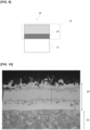
- Diffusion Layer such a diffusion layer can be identified by observing the cross section after nital etching with an optical microscope, as explained below. Further, when it is impossible to identify the diffusion layer by the observation with an optical microscope, the diffusion layer can be identified by analyzing the cross section with an electron probe micro analyzer (EPMA). In this event, in EPMA analysis results, a layer containing Al: 30 mass% or less and Fe: 70 mass% or more may be set as a diffusion layer 20.
- a layer 19 is a layer that mainly contains the ⁇ phase, the ⁇ 1 phase, and the FeAl phase, and includes the diffusion layer 20.
- the thickness of the Al-Fe-based alloy plated layer is measured as the thickness of the layer 19, and the thickness of the diffusion layer is measured as the thickness of the layer 20.
- FIG. 10 an example where a cross section was observed with an optical microscope after nital etching is illustrated in FIG. 10 .
- the thickness of the diffusion layer included in the Al-Fe-based alloy plated layer at the portion of the first Al-Fe-based alloy plated steel sheet that is not overlapped with the second Al-Fe-based alloy plated steel sheet is described as D1 ( ⁇ m)
- the thickness of the diffusion layer included in the Al-Fe-based alloy plated layer of the second Al-Fe-based alloy plated steel sheet is described as D2 ( ⁇ m).
- the upper limit of the heating time during the hot stamping heating is set to a short time of (t2 + ⁇ t2) (or t4 + ⁇ t4), and thus, it is possible to reduce the thicknesses D1 ( ⁇ m) and D2 ( ⁇ m) of the diffusion layers to 3 ⁇ m or more and 10 ⁇ m or less independently.
- the case where the thickness of the diffusion layer is 3 ⁇ m or more means that the plating is sufficiently alloyed, which makes it possible to prevent unalloyed Al from remaining on the surface and to prevent the decrease in spot weldability.
- the thickness of the diffusion layer is more preferably 4 ⁇ m or more, and further preferably 5 ⁇ m or more.
- the thickness of the diffusion layer is more preferably 9 ⁇ m or less, and further preferably 8 ⁇ m or less. As a result, the spot weldability of the one-sheet part improves in the hot stamped component 12 according to this embodiment.
- the cross section of the plating is subjected to nital etching in a field of view of 100 ⁇ m ⁇ 100 ⁇ m, and is observed with an optical microscope. As illustrated in FIG. 10 , the plating thickness and the thickness of the diffusion layer are measured with an optical microscope. More specifically, the cross section of the plating is observed through the above-described method at at least three locations, and the thickness of the Al-Fe-based alloy plated layer 19 and the thickness of the diffusion layer 20 at each observation location are specified.
- the obtained average values are calculated, and the obtained average values may be set to the thicknesses of the Al-Fe-based alloy plated layer 19 and the diffusion layer 20.
- an analysis is performed using an electron probe micro analyzer (EPMA), and the thickness of the layer containing Al: 30 mass% or less and Fe: 70 mass% or more is measured at at least three locations, and the average value of the measured thicknesses is set to the thickness of the diffusion layer 20.
- EPMA electron probe micro analyzer
- such a diffusion layer as described above is a layer formed by inward diffusion within the Al-based plated layer, and thus, the thicknesses D1 and D2 of the diffusion layers are strongly affected almost only by the heating conditions of hot stamping and are not affected by the initial plating thickness. Further, even if the plating coating weight on the second Al-based plated steel sheet is increased, it is impossible to make the thickness D2 of the diffusion layer of the second Al-Fe-based alloy plated steel sheet, which has a slower heating rate, substantially the same value as the thickness D1 of the diffusion layer of the first Al-Fe-based alloy plated steel sheet.
- the plating thicknesses K1 and K2 of the Al-Fe-based alloy plated layers are affected not only by the plating adhesion before hot stamping but also by the heating conditions (heating temperature, holding time) of hot stamping. Further, the plating thicknesses K1 and K2 of the Al-Fe-based alloy plated layers are affected not only by these factors, but also by the sheet thickness, which affects the heating time at high temperatures, and the lightness, and thus are not affected only by the initial plating thickness.
- the overlapped hot stamped component 12 in this embodiment when used as an automotive part, is generally used after being subjected to welding, phosphoric acid-based conversion treatment, electrodeposition coating, and so on. Accordingly, for example, a zinc phosphate coating and a phosphoric acid coating by the phosphoric acid-based conversion treatment, an organic coating of 5 ⁇ m or more and 50 ⁇ m or less by the electrodeposition coating on the surface of such coatings, and so on are formed on the surface of the hot stamped component 12 in some cases. For improving the external quality and corrosion resistance, coatings such as intermediate coating and finish coating are further performed after the electrodeposition coating in some cases.
- a first Al-based plated steel sheet 1 and a second Al-based plated steel sheet 2 listed in Table 1 were fabricated by the method to be described below, and were subjected to spot welding 3 as illustrated in FIG. 1 , and thereby an overlapped blank for hot stamping 4 was fabricated.
- the first Al-based plated steel sheet 1 a cold-rolled steel sheet through ordinary hot-rolling process and cold-rolling process and having (a chemical composition: by mass%, C: 0.23%, Si: 0.30%, Mn: 1.2%, P: 0.010%, S: 0.002%, Cr: 0.25%, Ti: 0.020%, Al: 0.042%, N: 0.0030%, B: 0.0020%, and the balance: Fe and impurities) was used as a sample material and an aluminum plating treatment was performed on its both faces on a Sendzimir hot-dip aluminum plating treatment line.
- the plating coating weight was adjusted to 80 g/m 2 per side by the gas wiping method, and then cooling was performed, and the first Al-based plated steel sheet 1 was fabricated.
- the plating bath composition in this event was 89 mass% Al-9 mass% Si-2 mass% Fe.
- a treatment was performed in which the face 1a in contact with the second Al-based plated steel sheet of the Al-based plated steel sheet of the first Al-based plated steel sheet was pickled (with 5% hydrochloric acid), to thereby reduce the lightness.
- a treatment was performed in which the face 1a in contact with the second Al-based plated steel sheet and the face 1b not in contact with the second Al-based plated steel sheet of the Al-based plated steel sheet of the first Al-based plated steel sheet were both pickled (with 5% hydrochloric acid), to thereby reduce the lightness.
- Levels A17 and A18 a treatment was performed in which by performing heating at 550°C, the Al-based plated layer on the surface was melted, to increase the lightness.
- the second Al-based plated steel sheet 2 was also fabricated in the same manner as the first Al-based plated steel sheet 1, and a carbon-based black coating was applied to the Al-based plated surface to have a film thickness of 0.5 to 8.0 ⁇ m.
- This blank was subjected to hot stamping heating at a heating temperature in Table 1 to investigate the temperature increasing rate of an overlapped part, and after being heated for a time in Table 1, the overlapped part was subjected to mold cooling at a cooling rate of 30°C/second or more after 8 seconds, and thereby an overlapped hot stamped component 12 was obtained.
- Two flange parts 11 of a non-overlapped part (one-sheet part) were cut out, and spot weldability was investigated with a pair of steel sheets of the same type.
- SC-T-GV5 spectrophotometric colorimeter
- the thicknesses D1 and D2 of the diffusion layers of the obtained overlapped hot stamped component were measured through cross-sectional observation using an optical microscope as described above (each was measured at three locations and the average value was found).
- the hardness of the second Al-based plated steel sheet at the overlapped part which is likely to have a low hardness because the thickness is thick and thus the heating rate is the slowest and the cooling rate by the metal mold is also slow, was measured from the cross section using a micro Vickers hardness tester under a load of 9.8107 N.
- the evaluation criteria are as follows, and Evaluation G was determined to be good, and Evaluation NG (No Good) was determined to be poor.
- Evaluation G3 Good 3 was determined to be good, VG (Very Good) was determined to be even better, and Evaluation NG (No Good) was determined to be poor.
- A2, A3, and A7 each being the invention example obtained more preferable evaluation results in which the spot weldability was determined to be VG because the heating time satisfied Equations (d), (e), and preferable Equation (f).
- A21 being the comparative example the value of the lightness L*b exceeded 60, and thus the hardness at the overlapped part was poor.
- the total sheet thickness of the first Al-based plated steel sheet and the second Al-based plated steel sheet was less than 2.5 mm, and thus the heating time was excessive and the spot weldability at the one-sheet part was poor.
- the total sheet thickness of the first Al-based plated steel sheet and the second Al-based plated steel sheet was greater than 4.8 mm, and thus the temperature increasing rate at the overlapped part was slow and the hardness at the overlapped part was poor.
- Level A3 in Example 1 Under the same manufacturing conditions as Level A3 in Example 1, a first Al-based plated steel sheet and a second Al-based plated steel sheet were fabricated, and a carbon-based black coating was formed on an Al-based plated layer of the second Al-based plated steel sheet. At this time, Levels A31, A32, and A33 were fabricated in which the plating coating weight on the second Al-based plated steel sheet was 55 g/m 2 , 45 g/m 2 , and 30 g/m 2 per side.
- Levels A3, A31, A32, and A33 obtained were heated under the conditions of Level A3 in Example 1, and quenched overlapped hot stamp molded bodies were obtained.
- a second Al-Fe-based alloy plated steel sheet was cut out from the obtained overlapped hot stamped component and spot welded under the same conditions as those described in Example 1, and the spot weldability of the second Al-Fe-based alloy plated steel sheet was evaluated.
- the score of Level A3 and Level A31 was VG, and the score of Level A32 and Level A33 was G.
- W1 - W21 obtained by subtracting the plating coating weight W2 of the second Al-based plated steel sheet from the plating coating weight W1 of the first Al-based plated steel sheet was 25 g/m 2 or less, which was within a preferable range
- W1 - W21 obtained by subtracting the plating coating weight W2 of the second Al-based plated steel sheet from the plating coating weight W1 of the first Al-based plated steel sheet was 35 g/m 2 or more, which was outside the above-described preferable range.
- the hardness at the overlapped part in Levels A31, A32 and A33 and the spot weldability of the one-sheet part in the first Al-Fe-based alloy plated steel sheet were determined to be score G and score VG, respectively, as in Level A3.
- Example 2 Under the same manufacturing conditions as in Example 1 listed in Table 2, a carbon-based black coating was applied to an Al-based plated surface at a non-overlapped part of each of a first Al-based plated steel sheet and a second Al-based plated steel sheet to have a film thickness of 0.5 to 8.0 ⁇ m.
- This blank was subjected to hot stamping heating at a heating temperature in Table 1 to investigate the temperature increasing rate of an overlapped part, and after being heated for a time in Table 1, the overlapped part was subjected to mold cooling at a cooling rate of 30°C/second or more after 8 seconds, and thereby an overlapped hot stamped component 12 was obtained.
- Level A1 being the comparative example in Table 1, the hardness at the overlapped part was poor with the same sheet thickness, heating temperature, and heating time, but Invention example B1 exhibited a good result in terms of the hardness at the overlapped part. Invention example B4 also had a good hardness at the overlapped part and good spot weldability at the one-sheet part. Regarding B2 and B3, in Level A10 being the comparative example in Table 1, the hardness at the overlapped part was poor with the same sheet thickness, heating temperature, and heating time, but Invention examples B2 to B4 exhibited a good result in terms of the hardness at the overlapped part.
Landscapes
- Chemical & Material Sciences (AREA)
- Engineering & Computer Science (AREA)
- Mechanical Engineering (AREA)
- Organic Chemistry (AREA)
- Materials Engineering (AREA)
- Metallurgy (AREA)
- Thermal Sciences (AREA)
- Physics & Mathematics (AREA)
- Crystallography & Structural Chemistry (AREA)
- Chemical Kinetics & Catalysis (AREA)
- Inorganic Chemistry (AREA)
- Life Sciences & Earth Sciences (AREA)
- Wood Science & Technology (AREA)
- Shaping Metal By Deep-Drawing, Or The Like (AREA)
- Heat Treatment Of Articles (AREA)
- Heat Treatment Of Sheet Steel (AREA)
- Coating With Molten Metal (AREA)
Applications Claiming Priority (2)
| Application Number | Priority Date | Filing Date | Title |
|---|---|---|---|
| JP2022082169 | 2022-05-19 | ||
| PCT/JP2023/018803 WO2023224123A1 (fr) | 2022-05-19 | 2023-05-19 | Procédé de production d'un corps moulé par estampage à chaud stratifié |
Publications (2)
| Publication Number | Publication Date |
|---|---|
| EP4484029A1 true EP4484029A1 (fr) | 2025-01-01 |
| EP4484029A4 EP4484029A4 (fr) | 2025-07-02 |
Family
ID=88835267
Family Applications (1)
| Application Number | Title | Priority Date | Filing Date |
|---|---|---|---|
| EP23807724.2A Pending EP4484029A4 (fr) | 2022-05-19 | 2023-05-19 | Procédé de production d'un corps moulé par estampage à chaud stratifié |
Country Status (7)
| Country | Link |
|---|---|
| EP (1) | EP4484029A4 (fr) |
| JP (1) | JP7425392B1 (fr) |
| KR (1) | KR20250006113A (fr) |
| CN (1) | CN119173345A (fr) |
| CA (1) | CA3246821A1 (fr) |
| MX (1) | MX2024012451A (fr) |
| WO (1) | WO2023224123A1 (fr) |
Cited By (1)
| Publication number | Priority date | Publication date | Assignee | Title |
|---|---|---|---|---|
| EP4527517A4 (fr) * | 2022-05-19 | 2025-11-12 | Nippon Steel Corp | Ébauche en couches pour estampage à chaud et corps moulé par estampage à chaud en couches |
Families Citing this family (1)
| Publication number | Priority date | Publication date | Assignee | Title |
|---|---|---|---|---|
| JP7827230B1 (ja) * | 2024-08-02 | 2026-03-10 | Jfeスチール株式会社 | 抵抗スポット溶接継手の製造方法及びめっき層の融点予測方法 |
Family Cites Families (18)
| Publication number | Priority date | Publication date | Assignee | Title |
|---|---|---|---|---|
| JPS6178301U (fr) | 1984-10-25 | 1986-05-26 | ||
| WO2002103073A2 (fr) | 2001-06-15 | 2002-12-27 | Nippon Steel Corporation | Tole d'acier plaque aluminium allie de haute resistance et piece automobile de haute resistance presentant une excellente resistance a la chaleur et a la corrosion apres peinture |
| MX2011000056A (es) | 2008-07-11 | 2011-04-27 | Nippon Steel Corp | Lamina de acero chapada con aluminio para prensado en caliente con calentamiento rapido, proceso para producir la misma, y metodo para prensar en caliente la misma con calentamento rapido. |
| CN102482741B (zh) | 2009-08-06 | 2013-10-16 | 新日铁住金株式会社 | 辐射传热加热用金属板及其制造方法、以及具有不同强度部分的金属加工件及其制造方法 |
| JP2011088484A (ja) | 2009-10-20 | 2011-05-06 | Toyota Motor Corp | 車両用骨格部材及びその製造方法 |
| JP5573195B2 (ja) * | 2010-01-25 | 2014-08-20 | 新日鐵住金株式会社 | 昇温特性に優れた熱間プレス用Alめっき鋼板及びその製造方法 |
| WO2015150848A1 (fr) * | 2014-03-31 | 2015-10-08 | Arcelormittal Investigación Y Desarrollo Sl | Procede de fabrication a haute productivite de pieces d'acier revêtues et durcies a la presse |
| JP6178301B2 (ja) | 2014-12-12 | 2017-08-09 | Jfeスチール株式会社 | 熱間プレス成形品の製造方法 |
| JP6451327B2 (ja) | 2015-01-08 | 2019-01-16 | 新日鐵住金株式会社 | ホットスタンプ用重ね合わせブランクと、重ね合わせホットスタンプ成形体の製造方法、および重ね合わせホットスタンプ成形体 |
| CA2978873C (fr) | 2015-03-06 | 2023-01-24 | Magna International Inc. | Proprietes de materiau adapte a l'aide d'un rayonnement infrarouge et revetements absorbants infrarouges |
| JP6682973B2 (ja) * | 2016-04-14 | 2020-04-15 | 日本製鉄株式会社 | 黒色塗装亜鉛系めっき鋼板及びその製造方法 |
| DE102017110864B3 (de) | 2017-05-18 | 2018-10-18 | Voestalpine Metal Forming Gmbh | Verfahren und Vorrichtung zum Erzeugen gehärteter Stahlblechbauteile mit unterschiedlichen Blechdicken |
| KR102010048B1 (ko) * | 2017-06-01 | 2019-10-21 | 주식회사 포스코 | 도장 밀착성과 도장 후 내식성이 우수한 열간 프레스 성형 부재용 강판 및 그 제조방법 |
| MX2020010274A (es) * | 2018-04-06 | 2020-11-06 | Nippon Steel Corp | Pieza en bruto superpuesta para estampado en caliente, metodo de fabricacion de cuerpo moldeado estampado en caliente superpuesto y cuerpo moldeado estampado en caliente superpuesto. |
| DE102019126378A1 (de) * | 2019-09-30 | 2021-04-01 | Salzgitter Flachstahl Gmbh | Verfahren zur Herstellung eines pressgehärteten Stahlblechbauteils mit einem aluminiumbasierten Überzug sowie eine Ausgangsplatine und ein pressgehärtetes Stahlblechbauteil hieraus |
| CN113924373B (zh) * | 2019-12-20 | 2023-09-01 | 现代制铁株式会社 | 热冲压部件及其制造方法 |
| US12311427B2 (en) | 2020-02-26 | 2025-05-27 | Nippon Steel Corporation | Method of manufacturing overlapped hot stamp molded body, and overlapped hot stamp molded body |
| JP7477753B2 (ja) * | 2020-03-30 | 2024-05-02 | 日本製鉄株式会社 | 重ね合わせブランク、および、それを用いたホットスタンプ成形体の製造方法 |
-
2023
- 2023-05-19 KR KR1020247037677A patent/KR20250006113A/ko active Pending
- 2023-05-19 CA CA3246821A patent/CA3246821A1/fr active Pending
- 2023-05-19 JP JP2023546358A patent/JP7425392B1/ja active Active
- 2023-05-19 CN CN202380039445.8A patent/CN119173345A/zh active Pending
- 2023-05-19 EP EP23807724.2A patent/EP4484029A4/fr active Pending
- 2023-05-19 WO PCT/JP2023/018803 patent/WO2023224123A1/fr not_active Ceased
-
2024
- 2024-10-07 MX MX2024012451A patent/MX2024012451A/es unknown
Cited By (1)
| Publication number | Priority date | Publication date | Assignee | Title |
|---|---|---|---|---|
| EP4527517A4 (fr) * | 2022-05-19 | 2025-11-12 | Nippon Steel Corp | Ébauche en couches pour estampage à chaud et corps moulé par estampage à chaud en couches |
Also Published As
| Publication number | Publication date |
|---|---|
| EP4484029A4 (fr) | 2025-07-02 |
| MX2024012451A (es) | 2024-11-08 |
| KR20250006113A (ko) | 2025-01-10 |
| CN119173345A (zh) | 2024-12-20 |
| WO2023224123A1 (fr) | 2023-11-23 |
| JP7425392B1 (ja) | 2024-01-31 |
| CA3246821A1 (fr) | 2025-02-03 |
| JPWO2023224123A1 (fr) | 2023-11-23 |
Similar Documents
| Publication | Publication Date | Title |
|---|---|---|
| US11364707B2 (en) | Overlapped blank for hot stamping, method of manufacturing overlapped hot stamp molded body, and overlapped hot stamp molded body | |
| CN111511942B (zh) | 镀铝系钢板、镀铝系钢板的制造方法及汽车用部件的制造方法 | |
| EP3623493B1 (fr) | Élément estampé à chaud revetu avec une alliage en fe-al et procédé de production d'élément fe-al plaqué estampé à chaud | |
| EP2312005B1 (fr) | Tôle d' acier plaquée d' aluminium pour estampage à chaud à chauffage rapide, procédé de celle-ci et procédé d'estampage à chaud à chauffage rapide en utilisant ladite tôle | |
| EP3088558B1 (fr) | Feuille d'acier pour formation par pressage à chaud ayant une excellente résistance à la corrosion et une excellente soudabilité, élément de formation et son procédé de fabrication | |
| EP3395979B1 (fr) | Tôle d'acier à base d'austénite plaquée d'aluminium fondu ayant d'excellentes propriétés de plaquage et de soudabilité et son procédé de fabrication | |
| US11807940B2 (en) | Plated steel material | |
| JP7425392B1 (ja) | 重ね合わせホットスタンプ成形体の製造方法 | |
| US20250262841A1 (en) | Overlapped blank for hot stamping and overlapped hot stamped component | |
| EP3396005B1 (fr) | Tôle d'acier contenant du manganèse, recuite après galvanisation par immersion à chaud et son procédé de fabrication | |
| JP7495009B2 (ja) | 熱間プレス用鋼板、熱間プレス用鋼板の製造方法、および熱間プレス部材の製造方法 | |
| KR20220016491A (ko) | 부식방지 코팅이 구비된 강판 제품으로부터 판금 부품을 제조하는 방법 | |
| EP4386093A1 (fr) | Pièce assemblée et tôle d'acier assemblée | |
| WO2023135981A1 (fr) | Article moulé estampé à chaud | |
| EP4206363A1 (fr) | Élément pressé à chaud et tôle d'acier pour pressage à chaud, et procédé de fabrication pour élément pressé à chaud | |
| US12629741B2 (en) | Steel sheet for hot press forming, method of producing steel sheet for hot press forming, and method of producing hot pressed member | |
| WO2023074115A1 (fr) | Élément pressé à chaud |
Legal Events
| Date | Code | Title | Description |
|---|---|---|---|
| STAA | Information on the status of an ep patent application or granted ep patent |
Free format text: STATUS: THE INTERNATIONAL PUBLICATION HAS BEEN MADE |
|
| PUAI | Public reference made under article 153(3) epc to a published international application that has entered the european phase |
Free format text: ORIGINAL CODE: 0009012 |
|
| STAA | Information on the status of an ep patent application or granted ep patent |
Free format text: STATUS: REQUEST FOR EXAMINATION WAS MADE |
|
| 17P | Request for examination filed |
Effective date: 20240926 |
|
| AK | Designated contracting states |
Kind code of ref document: A1 Designated state(s): AL AT BE BG CH CY CZ DE DK EE ES FI FR GB GR HR HU IE IS IT LI LT LU LV MC ME MK MT NL NO PL PT RO RS SE SI SK SM TR |
|
| TPAC | Observations filed by third parties |
Free format text: ORIGINAL CODE: EPIDOSNTIPA |
|
| REG | Reference to a national code |
Ref country code: DE Ref legal event code: R079 Free format text: PREVIOUS MAIN CLASS: B21D0022200000 Ipc: C21D0009000000 |
|
| A4 | Supplementary search report drawn up and despatched |
Effective date: 20250602 |
|
| RIC1 | Information provided on ipc code assigned before grant |
Ipc: C21D 1/673 20060101ALN20250526BHEP Ipc: B21D 22/02 20060101ALN20250526BHEP Ipc: B21D 35/00 20060101ALN20250526BHEP Ipc: C09D 7/61 20180101ALI20250526BHEP Ipc: C08K 3/04 20060101ALI20250526BHEP Ipc: C23C 2/40 20060101ALI20250526BHEP Ipc: C23C 2/26 20060101ALI20250526BHEP Ipc: C23C 2/12 20060101ALI20250526BHEP Ipc: C21D 9/48 20060101ALI20250526BHEP Ipc: C21D 8/00 20060101ALI20250526BHEP Ipc: C21D 1/70 20060101ALI20250526BHEP Ipc: B32B 15/01 20060101ALI20250526BHEP Ipc: C21D 9/00 20060101AFI20250526BHEP |
|
| DAV | Request for validation of the european patent (deleted) | ||
| DAX | Request for extension of the european patent (deleted) |