EP4484092A1 - Körperpflegevorrichtung wie elektrischer haarschneider mit beleuchtungseinheit - Google Patents
Körperpflegevorrichtung wie elektrischer haarschneider mit beleuchtungseinheit Download PDFInfo
- Publication number
- EP4484092A1 EP4484092A1 EP24185010.6A EP24185010A EP4484092A1 EP 4484092 A1 EP4484092 A1 EP 4484092A1 EP 24185010 A EP24185010 A EP 24185010A EP 4484092 A1 EP4484092 A1 EP 4484092A1
- Authority
- EP
- European Patent Office
- Prior art keywords
- light
- light guide
- housing
- inner housing
- personal care
- Prior art date
- Legal status (The legal status is an assumption and is not a legal conclusion. Google has not performed a legal analysis and makes no representation as to the accuracy of the status listed.)
- Granted
Links
Images





Classifications
-
- B—PERFORMING OPERATIONS; TRANSPORTING
- B26—HAND CUTTING TOOLS; CUTTING; SEVERING
- B26B—HAND-HELD CUTTING TOOLS NOT OTHERWISE PROVIDED FOR
- B26B19/00—Clippers or shavers operating with a plurality of cutting edges, e.g. hair clippers, dry shavers
- B26B19/38—Details of, or accessories for, hair clippers, or dry shavers, e.g. housings, casings, grips, guards
- B26B19/46—Details of, or accessories for, hair clippers, or dry shavers, e.g. housings, casings, grips, guards providing for illuminating the area to be shaved or clipped
Definitions
- the present invention relates to a personal care device, in particular an electric hair trimmer, comprising an elongated housing receiving an electric motor and/or an electric power source, a working head attached to said housing, and an illumination unit for illuminating the working head and/or a surrounding area, wherein said illumination unit includes a light guide for guiding light from a light source to a light emitting member.
- Electric hair trimmer and other hair removal devices such as shavers or epilators usually have one or more cutter elements driven by an electric drive unit in an oscillating or continuous manner to rotate or reciprocate wherein the cutter elements may cooperate with a comb-like cutter bar or other co-operative counter elements such as a shear foil.
- the electric drive unit may include an electric motor or a magnetic-type linear motor, wherein the drive unit may include a drive train having elements such as an elongated drive transmitter for transmitting the driving motion of the motor to the cutter element, wherein said motor, a power source such as a battery and electronics may be received within the handle portion of the hand held personal care device.
- the hand held personal care devices may be provided with an illumination unit including a light source such as an LED and some sort of optics to get the light directed onto the areas to be illuminated.
- a light source such as an LED
- optics may include a light guide for guiding the light from the light source to a light emitting member to allow the light source being spaced apart from the light emitting surface and in particular being positioned inside the housing even when the light emitting surface is on the outside of the housing. Accommodation of the light source inside the housing does not only protect the light source against moisture, dirt and other environmental damages, but helps in making power supply and linkage to the controller easy.
- the housing accommodating the electric motor, the electric power source, electronics and also the light source of the illumination unit often includes an elongated base element closed by a cover element to allow for mounting and accommodating the electronic components inside the housing.
- a seal is provided between the base element and the cover element, wherein such seal may include a sealing ring extending between surfaces of the base element and the cover element facing each other.
- the outer housing may have a two-piece or three-piece or multiple-piece shell structure comprising a plurality of shell elements that can be connected with each other and cover different portions of the inner housing.
- the outer housing may comprise two shell elements extending on opposite sides of the inner housing and connectable to each other.
- Such shell elements may have a substantially - roughly speaking - flute-like or chute-like contour so that the two shell elements together may surround the inner housing substantially completely.
- An elongated drive transmitter 9 may extend from the handle 2 into the working head 5 so as to connect the cutter elements 4 to a motor 93 which may be accomodated in the interior of the handle 2.
- the housing 3 forming the handle 2 may have a two-shell structure comprising an inner housing 3i and an outer housing 3o surrounding said inner housing 3i.
- the inner housing 3i accomodates the aforementioned motor 93 and furthermore, an electrical storage such as batteries or an accumulator, and an electronic control unit, cf. Fig. 13 , wherein the inner housing 3i may form a water-tight container protecting such components from liquids and moisture.
- the inner housing 3i may have an elongated barrel-like structure including a cup-shaped or pot-like base element 306 having a closed bottom and an open top face, wherein such base element may extend substantially over the entire length of the handle 2.
- the base element 306 is closed, at its open top side, by a cover element 307 which may have a plate-like or slightly dome-like shape and, when closing the base element 306, forms a front face side of the inner housing 3i facing the working head 5.
- the aforementioned cover element 307 includes an opening through which the motor shaft or transmitter 9 penetrates the housing, wherein the cover element 307 is sealed, by means of appropriate seals 400, against said shaft or transmitter and against the base element 306 so that the inner housing 3i forms a waterproof container.
- the outer housing 3o may have a shell structure including a pair of elongated shell elements and which together may surround the inner housing 3i substantially entirely.
- the shell elements may extend substantially over the entire length of the inner housing 3i and/or the handle 2.
- Said shell elements 304 and 305 may be positioned on opposite sides of the inner housing 3i and may be connected to each other so that they together form the gripping surface of the substantially cone-shaped or cylindrical handle 2.
- the outer housing 3o may include a ring element 303 forming, at least in part, a top side surface of the outer housing 3o facing the working head 3. Said ring element 303 is connected to at least one of the shell elements 304 and 305.
- Fig. 7 shows a perspective bottom view of the interior housing cover element showing the inlet side of the light guide to be connected to the light source at the bottom portion of said cover element. As shown therefrom the lightguide and the cover part of the inner housing are made as integral part.
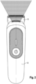
- the inner housing 3i also accommodates the light source 12 of an illumination unit 10 for illuminating the working head 5 and a surrounding working area, in particular the elongated cutter unit 100 and the neighboring ambient area where hairs to be cut or skin to be shaved may be expected.
- the illumination unit 10 includes a light guide 11 extending from said light source 12 to an outer surface of the outer housing 3o.
- Such light guide 11 may be a form material body made from plastic and may have a configuration to achieve total internal reflection so substantially no light exits the light guide 11 at its circumferential side or at its medium portion between the inlet end portion 14 and the outlet end portion 16.
- said light guide 11 extends through the outer housing 3o and through the inner housing 3i, wherein the light guide 11 is sealed against said inner housing 3i.
- the inlet end portion 14 of the light guide 11 may form an integral part of or a portion of the inner housing 3i. More particularly, the inlet end portion 14 may form a part of the cover element 307 of inner housing 3i and, thus, may form a part of the bottom portion of said cover element 307, cf. Fig. 6 .
- the light guide 11 may be sealed to the inner housing 3i by means of welding such as laser welding, gluing or by means of sealing elements or sealing layers.
- the light guide 11 and the inner housing 3i may form an integral one-piece structure. More particularly, the light guide 11 and the inner housing 3i may be a two-component molding part that may be formed by a two-step or multiple step injection molding process from plastic.
- the light guide 11 may be formed from transparent plastic, whereas the inner housing 3i may be formed from non-transparent plastic.
- the cover element 307 of inner housing 3i may be injection-molded in a first step to have a throughhole for the light guide 11. In a second injection molding step, the light guide 11 may be molded to fill out such throughhole in the cover element 307.
- the light guide is reliably sealed against the inner housing 3i.
- the light source 12 which may be an LED or an LED cluster, may be positioned directly adjacent to the inlet side of the light guide 11.
- the inlet end portion 14 of the light guide 11 may be provided with a concavity or a recess in its front end side to face the light source 12 which may be accommodated at least partly in the interior of such recess. More particularly, the light receiving surface 15 at which light from the light source 12 is coupled into the light guide 11, may be provided with such recess, cf. Fig. 6 .
- Such cavity or recess allows the light guide 11 to surround the light source 12 on a peripheral side so the light guide 11 may catch substantially the entire light emitted from the light source 12.
- LEDs are usually half space emitters, i.e. emit light into a hemisphere, substantially the entire light is getting into the light guide, thereby achieving high efficiency.
- the light-emitting surface 17 of the light guide 11 may be positioned close to the working head 5 and, more particularly, very close to the elongated cutter unit 100.
- the light guide 11 may extend, in the longitudinal direction 20 of the handle 2, beyond the transmitter 9 which is transmitting the driving action of the motor 93 into the working head 5.
- the light-emitting surface 17 may be further spaced from the light source 12 than from the elongated cutter unit 100.
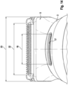
- the light emitting surface 17 may be spaced apart from the working tool units by a distance that is smaller than a length of the elongated light emitting surface 18, cf. Fig. 1 and Fig. 4 and Fig. 14 .
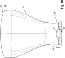
- the cross-section of the light guide 11 continuously increases from the inlet end portion 14 to the outlet end portion 16.
- the entire light guide 11 may have a substantially tongue-like shape, wherein it gets wider or longer towards the light-emitting surface 17.
- the cross-sectional area at the outlet end portion 16 may be more than 200% or more than 300% of the cross-sectional area at the inlet end portion.
- the light guide 11 extends along a main axis or a longitudinal axis 21 which is not straight, but has a curved configuration. More particularly, the longitudinal axis 21 of the light guide 11 may have an S-shape or a sinus-like shape. Due to such curvature to opposite sides, the light transmitted by the light guide 11 gets mixed and, thus, more homogeneous. At the same time, the light guide 11 may better follow the outer shape of the rounded outer housing 3o although it comes from the inner housing 3i.
- the inlet end portion 14 and the outlet end portion 16 of the light guide are laterally offset relative to each other and furthermore, may be inclined relative to each other. Similarily, the light receiving surface 15 and the light emitting surface 17 may be laterally offset and/or inclined relative to each other.
- the light guide 11 may end on an outer side of the outer housing 3o having a three-dimensional curvature.
- the outer housing 3o at least at its portion close to the working head 3, may be rounded due to its substantially - roughly speaking - cylindrical shape and, at the same time, it may have curvature in a longitudinal cross-section, thus defining a three-dimensional curvature.
- the light-emitting surface 17 basically follows such three-dimensional shape of the outer side of the outer housing 3o and, more particularly, it may be substantially flush with such outer surface.
- the light-emitting surface 17 may have a cascaded or stepped contour, cf. Fig. 8 and Fig. 6 and also Fig. 3 , wherein such cascaded contour may include elongated ribs or elongated facets extending along the elongated shape of the light-emitting surface 17.
- the stepped surfaces, in particular the front surfaces of the stepped contour are directly facing the target area that should be illuminated and, thus, light emitted from such front faces of the stepped contour directly illuminate the target area surrounding the working unit 100.
- the light-emitting surface 17 may be substantially flush with the multi-axially curved outer surface of the housing 3.
- the outermost edges of the light-emitting surface 17 may be flush with the neighboring housing walls and the stepped surfaces therebetween may direct the light towards the target area.
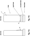
- Figs. 11a and 11b illustrate schematically the overall arrangement of the light emitting surface of the light guide relative to the blades.
- the blades of the cutter unit 100 are well illuminated over its full teethed extension from the lower side thereof.
- Fig. 12 illustrates the the light guide being arrange such that the light cone emitting onto the cutting unit and some portion of the users treating zone before that. See also Fig. 2 showing the light beam spreading at an angle that is sufficient to illuminate the cutting unit blades over its full width, so over all cutting teeth.
- the length 18 of the light-emitting surface 17 may be more than 50% of the length 22 of the elongated cutter unit 100, i.e. the length of the extension of the cutting teeth on the cutting unit's blades.
Landscapes
- Life Sciences & Earth Sciences (AREA)
- Forests & Forestry (AREA)
- Engineering & Computer Science (AREA)
- Mechanical Engineering (AREA)
- Non-Portable Lighting Devices Or Systems Thereof (AREA)
Applications Claiming Priority (1)
| Application Number | Priority Date | Filing Date | Title |
|---|---|---|---|
| EP23182816 | 2023-06-30 |
Publications (2)
| Publication Number | Publication Date |
|---|---|
| EP4484092A1 true EP4484092A1 (de) | 2025-01-01 |
| EP4484092B1 EP4484092B1 (de) | 2026-04-08 |
Family
ID=87059977
Family Applications (1)
| Application Number | Title | Priority Date | Filing Date |
|---|---|---|---|
| EP24185010.6A Active EP4484092B1 (de) | 2023-06-30 | 2024-06-27 | Körperpflegevorrichtung wie elektrischer haarschneider mit beleuchtungseinheit |
Country Status (3)
| Country | Link |
|---|---|
| US (1) | US20250001634A1 (de) |
| EP (1) | EP4484092B1 (de) |
| WO (1) | WO2025003943A1 (de) |
Families Citing this family (2)
| Publication number | Priority date | Publication date | Assignee | Title |
|---|---|---|---|---|
| USD1114386S1 (en) * | 2023-03-24 | 2026-02-17 | Shenzhen Shouzheng Chuqi Technology Co., Ltd. | Pet clipper |
| US12611788B1 (en) * | 2025-08-28 | 2026-04-28 | Nature Lab Corporation | Electric hair trimmer with illumination system |
Citations (5)
| Publication number | Priority date | Publication date | Assignee | Title |
|---|---|---|---|---|
| EP2851167A1 (de) * | 2013-09-24 | 2015-03-25 | Exonda Salon Tools GmbH | Haarschneidevorrichtung mit integrierter Lichtquelle und integriertem Lichtleiter |
| EP3546155A1 (de) * | 2018-03-29 | 2019-10-02 | Braun GmbH | Körperpflegevorrichtung wie etwa elektrischer rasierer |
| WO2021032578A1 (en) | 2019-08-20 | 2021-02-25 | Koninklijke Philips N.V. | Hand held personal care device with a light system |
| US20220273408A1 (en) * | 2019-08-19 | 2022-09-01 | Oralucent, Inc. | Light emitting oscillating toothbrush |
| EP4147834A1 (de) * | 2021-09-09 | 2023-03-15 | Koninklijke Philips N.V. | Rasiereinheit und elektrischer rasierapparat damit |
-
2024
- 2024-06-27 WO PCT/IB2024/056259 patent/WO2025003943A1/en not_active Ceased
- 2024-06-27 US US18/757,016 patent/US20250001634A1/en active Pending
- 2024-06-27 EP EP24185010.6A patent/EP4484092B1/de active Active
Patent Citations (5)
| Publication number | Priority date | Publication date | Assignee | Title |
|---|---|---|---|---|
| EP2851167A1 (de) * | 2013-09-24 | 2015-03-25 | Exonda Salon Tools GmbH | Haarschneidevorrichtung mit integrierter Lichtquelle und integriertem Lichtleiter |
| EP3546155A1 (de) * | 2018-03-29 | 2019-10-02 | Braun GmbH | Körperpflegevorrichtung wie etwa elektrischer rasierer |
| US20220273408A1 (en) * | 2019-08-19 | 2022-09-01 | Oralucent, Inc. | Light emitting oscillating toothbrush |
| WO2021032578A1 (en) | 2019-08-20 | 2021-02-25 | Koninklijke Philips N.V. | Hand held personal care device with a light system |
| EP4147834A1 (de) * | 2021-09-09 | 2023-03-15 | Koninklijke Philips N.V. | Rasiereinheit und elektrischer rasierapparat damit |
Also Published As
| Publication number | Publication date |
|---|---|
| WO2025003943A1 (en) | 2025-01-02 |
| US20250001634A1 (en) | 2025-01-02 |
| EP4484092B1 (de) | 2026-04-08 |
Similar Documents
| Publication | Publication Date | Title |
|---|---|---|
| EP4484092B1 (de) | Körperpflegevorrichtung wie elektrischer haarschneider mit beleuchtungseinheit | |
| KR101658763B1 (ko) | 구강 위생 기구 | |
| US6067714A (en) | Turbo cleaning illuminated personal groomer | |
| US11458644B2 (en) | Electric shaver | |
| CN101489741B (zh) | 剃刀 | |
| JP6278493B2 (ja) | 医療用鈎 | |
| JP7270838B2 (ja) | 照明システムを備えたハンドヘルド型パーソナルケア装置 | |
| JP6876506B2 (ja) | 電気かみそり | |
| CN104136177B (zh) | 链锯 | |
| EP3546155B1 (de) | Körperpflegevorrichtung wie etwa elektrischer rasierer | |
| US20170144319A1 (en) | Blade set, hair cutting appliance, and related manufacturing method | |
| US20120124758A1 (en) | Powered brush | |
| EP1663056A2 (de) | Elektrische zahnbürste mit einem elektrisch angetriebenen element | |
| JP6849809B2 (ja) | 光源を有するかみそり | |
| JP6882489B2 (ja) | 光源を有するかみそり | |
| WO2016200582A1 (en) | Mirror with integral light pipe illumination | |
| KR20220043148A (ko) | 제모 장치, 제모 조립체, 및 그의 조립 방법 | |
| CN205466348U (zh) | 带照明功能的剃毛器 | |
| JP6468645B2 (ja) | 電気かみそり | |
| DK2851167T3 (en) | Hair clipping device with integrated light source and integrated light guide | |
| JP5827824B2 (ja) | 電動歯ブラシ | |
| EP4703102A1 (de) | Gehäuseanordnung für eine pflegevorrichtung | |
| CN215943015U (zh) | 一种具有照明功能的动物理发剪用动刀片 | |
| JP2004254629A (ja) | 手持ち式刈り取り機 | |
| MXPA04002093A (es) | Rasuradora electrica de tiempo reciprocante. |
Legal Events
| Date | Code | Title | Description |
|---|---|---|---|
| PUAI | Public reference made under article 153(3) epc to a published international application that has entered the european phase |
Free format text: ORIGINAL CODE: 0009012 |
|
| STAA | Information on the status of an ep patent application or granted ep patent |
Free format text: STATUS: THE APPLICATION HAS BEEN PUBLISHED |
|
| AK | Designated contracting states |
Kind code of ref document: A1 Designated state(s): AL AT BE BG CH CY CZ DE DK EE ES FI FR GB GR HR HU IE IS IT LI LT LU LV MC ME MK MT NL NO PL PT RO RS SE SI SK SM TR |
|
| STAA | Information on the status of an ep patent application or granted ep patent |
Free format text: STATUS: REQUEST FOR EXAMINATION WAS MADE |
|
| 17P | Request for examination filed |
Effective date: 20250625 |
|
| GRAP | Despatch of communication of intention to grant a patent |
Free format text: ORIGINAL CODE: EPIDOSNIGR1 |
|
| STAA | Information on the status of an ep patent application or granted ep patent |
Free format text: STATUS: GRANT OF PATENT IS INTENDED |
|
| INTG | Intention to grant announced |
Effective date: 20251107 |
|
| GRAS | Grant fee paid |
Free format text: ORIGINAL CODE: EPIDOSNIGR3 |
|
| GRAA | (expected) grant |
Free format text: ORIGINAL CODE: 0009210 |
|
| STAA | Information on the status of an ep patent application or granted ep patent |
Free format text: STATUS: THE PATENT HAS BEEN GRANTED |
|
| AK | Designated contracting states |
Kind code of ref document: B1 Designated state(s): AL AT BE BG CH CY CZ DE DK EE ES FI FR GB GR HR HU IE IS IT LI LT LU LV MC ME MK MT NL NO PL PT RO RS SE SI SK SM TR |
|
| REG | Reference to a national code |
Ref country code: CH Ref legal event code: F10 Free format text: ST27 STATUS EVENT CODE: U-0-0-F10-F00 (AS PROVIDED BY THE NATIONAL OFFICE) Effective date: 20260408 Ref country code: GB Ref legal event code: FG4D |
|
| REG | Reference to a national code |
Ref country code: DE Ref legal event code: R096 Ref document number: 602024003775 Country of ref document: DE |