EP4484096A2 - Système de préparation prêt à la consommation de fruits pendant le commerce stationnaire - Google Patents
Système de préparation prêt à la consommation de fruits pendant le commerce stationnaire Download PDFInfo
- Publication number
- EP4484096A2 EP4484096A2 EP24212844.5A EP24212844A EP4484096A2 EP 4484096 A2 EP4484096 A2 EP 4484096A2 EP 24212844 A EP24212844 A EP 24212844A EP 4484096 A2 EP4484096 A2 EP 4484096A2
- Authority
- EP
- European Patent Office
- Prior art keywords
- fruit
- fan
- pineapple fruit
- air flow
- air
- Prior art date
- Legal status (The legal status is an assumption and is not a legal conclusion. Google has not performed a legal analysis and makes no representation as to the accuracy of the status listed.)
- Pending
Links
Images
Classifications
-
- B—PERFORMING OPERATIONS; TRANSPORTING
- B26—HAND CUTTING TOOLS; CUTTING; SEVERING
- B26D—CUTTING; DETAILS COMMON TO MACHINES FOR PERFORATING, PUNCHING, CUTTING-OUT, STAMPING-OUT OR SEVERING
- B26D1/00—Cutting through work characterised by the nature or movement of the cutting member or particular materials not otherwise provided for; Apparatus or machines therefor; Cutting members therefor
- B26D1/01—Cutting through work characterised by the nature or movement of the cutting member or particular materials not otherwise provided for; Apparatus or machines therefor; Cutting members therefor involving a cutting member which does not travel with the work
- B26D1/02—Cutting through work characterised by the nature or movement of the cutting member or particular materials not otherwise provided for; Apparatus or machines therefor; Cutting members therefor involving a cutting member which does not travel with the work having a stationary cutting member
- B26D1/03—Cutting through work characterised by the nature or movement of the cutting member or particular materials not otherwise provided for; Apparatus or machines therefor; Cutting members therefor involving a cutting member which does not travel with the work having a stationary cutting member with a plurality of cutting members
-
- A—HUMAN NECESSITIES
- A23—FOODS OR FOODSTUFFS; TREATMENT THEREOF, NOT COVERED BY OTHER CLASSES
- A23N—MACHINES OR APPARATUS FOR TREATING HARVESTED FRUIT, VEGETABLES OR FLOWER BULBS IN BULK, NOT OTHERWISE PROVIDED FOR; PEELING VEGETABLES OR FRUIT IN BULK; APPARATUS FOR PREPARING ANIMAL FEEDING- STUFFS
- A23N15/00—Machines or apparatus for other treatment of fruits or vegetables for human purposes; Machines or apparatus for topping or skinning flower bulbs
- A23N15/04—Devices for topping fruit or vegetables
-
- A—HUMAN NECESSITIES
- A23—FOODS OR FOODSTUFFS; TREATMENT THEREOF, NOT COVERED BY OTHER CLASSES
- A23N—MACHINES OR APPARATUS FOR TREATING HARVESTED FRUIT, VEGETABLES OR FLOWER BULBS IN BULK, NOT OTHERWISE PROVIDED FOR; PEELING VEGETABLES OR FRUIT IN BULK; APPARATUS FOR PREPARING ANIMAL FEEDING- STUFFS
- A23N4/00—Machines for stoning fruit or removing seed-containing sections from fruit, characterised by their stoning or removing device
- A23N4/12—Machines for stoning fruit or removing seed-containing sections from fruit, characterised by their stoning or removing device for coring fruit
- A23N4/20—Machines for stoning fruit or removing seed-containing sections from fruit, characterised by their stoning or removing device for coring fruit for pineapples
-
- A—HUMAN NECESSITIES
- A23—FOODS OR FOODSTUFFS; TREATMENT THEREOF, NOT COVERED BY OTHER CLASSES
- A23N—MACHINES OR APPARATUS FOR TREATING HARVESTED FRUIT, VEGETABLES OR FLOWER BULBS IN BULK, NOT OTHERWISE PROVIDED FOR; PEELING VEGETABLES OR FRUIT IN BULK; APPARATUS FOR PREPARING ANIMAL FEEDING- STUFFS
- A23N7/00—Peeling vegetables or fruit
- A23N7/002—Peeling pinaeapples
-
- B—PERFORMING OPERATIONS; TRANSPORTING
- B26—HAND CUTTING TOOLS; CUTTING; SEVERING
- B26D—CUTTING; DETAILS COMMON TO MACHINES FOR PERFORATING, PUNCHING, CUTTING-OUT, STAMPING-OUT OR SEVERING
- B26D1/00—Cutting through work characterised by the nature or movement of the cutting member or particular materials not otherwise provided for; Apparatus or machines therefor; Cutting members therefor
- B26D1/01—Cutting through work characterised by the nature or movement of the cutting member or particular materials not otherwise provided for; Apparatus or machines therefor; Cutting members therefor involving a cutting member which does not travel with the work
- B26D1/04—Cutting through work characterised by the nature or movement of the cutting member or particular materials not otherwise provided for; Apparatus or machines therefor; Cutting members therefor involving a cutting member which does not travel with the work having a linearly-movable cutting member
- B26D1/06—Cutting through work characterised by the nature or movement of the cutting member or particular materials not otherwise provided for; Apparatus or machines therefor; Cutting members therefor involving a cutting member which does not travel with the work having a linearly-movable cutting member wherein the cutting member reciprocates
- B26D1/10—Cutting through work characterised by the nature or movement of the cutting member or particular materials not otherwise provided for; Apparatus or machines therefor; Cutting members therefor involving a cutting member which does not travel with the work having a linearly-movable cutting member wherein the cutting member reciprocates in, or substantially in, a direction parallel to the cutting edge
- B26D1/11—Cutting through work characterised by the nature or movement of the cutting member or particular materials not otherwise provided for; Apparatus or machines therefor; Cutting members therefor involving a cutting member which does not travel with the work having a linearly-movable cutting member wherein the cutting member reciprocates in, or substantially in, a direction parallel to the cutting edge with a plurality of cutting members
-
- B—PERFORMING OPERATIONS; TRANSPORTING
- B26—HAND CUTTING TOOLS; CUTTING; SEVERING
- B26D—CUTTING; DETAILS COMMON TO MACHINES FOR PERFORATING, PUNCHING, CUTTING-OUT, STAMPING-OUT OR SEVERING
- B26D3/00—Cutting work characterised by the nature of the cut made; Apparatus therefor
- B26D3/24—Cutting work characterised by the nature of the cut made; Apparatus therefor to obtain segments other than slices, e.g. cutting pies
- B26D3/26—Cutting work characterised by the nature of the cut made; Apparatus therefor to obtain segments other than slices, e.g. cutting pies specially adapted for cutting fruit or vegetables, e.g. for onions
-
- B—PERFORMING OPERATIONS; TRANSPORTING
- B26—HAND CUTTING TOOLS; CUTTING; SEVERING
- B26D—CUTTING; DETAILS COMMON TO MACHINES FOR PERFORATING, PUNCHING, CUTTING-OUT, STAMPING-OUT OR SEVERING
- B26D7/00—Details of apparatus for cutting, cutting-out, stamping-out, punching, perforating, or severing by means other than cutting
- B26D2007/0012—Details, accessories or auxiliary or special operations not otherwise provided for
- B26D2007/0025—Sterilizing
-
- B—PERFORMING OPERATIONS; TRANSPORTING
- B26—HAND CUTTING TOOLS; CUTTING; SEVERING
- B26D—CUTTING; DETAILS COMMON TO MACHINES FOR PERFORATING, PUNCHING, CUTTING-OUT, STAMPING-OUT OR SEVERING
- B26D7/00—Details of apparatus for cutting, cutting-out, stamping-out, punching, perforating, or severing by means other than cutting
- B26D7/06—Arrangements for feeding or delivering work of other than sheet, web, or filamentary form
Definitions
- the invention relates to a system for processing foodstuffs, in particular for preparing a pineapple fruit ready for consumption in stationary retail.
- Pineapples are usually peeled by hand with a knife or processed at home with a special device or with a so-called pineapple cutter.
- Such a pineapple cutter is usually designed with an elongated hollow cylinder with a knife arranged on the outside.
- the knife is designed in such a way that the pineapple cutter is driven through the pineapple in a rotating motion, similar to that of a screw being screwed into a thread. This cuts the edible flesh of the pineapple fruit in a spiral shape and at the same time, due to the hollow cylindrical design of the pineapple cutter, the inedible core is removed.
- the spiral-cut flesh is usually cut into smaller portions by hand.
- Such preparation of a pineapple fruit is, on the one hand, time-consuming for consumers, involves effort in cutting up the pineapple fruit and, as a result, causes the pineapple cutter and plates to be washed.
- the object of the present invention is to provide a system for processing food, in particular fruit, for consumption and in particular for preparing a pineapple fruit ready for consumption in stores, which can be produced inexpensively and with little use of materials. Furthermore, the system should be able to be made available in stationary stores, with the preparation or cutting of a pineapple fruit preferably taking place automatically. In particular, the occurrence of fruit flies in the vicinity of the system should be avoided.
- the processing space can, for example, comprise a volume in which the processing of the food is carried out. It can also comprise a space for storing food, for supplying food for processing, for dispensing processed food and/or for receiving waste during the processing of the food.
- the processing space can also be at least partially lined with glass on the outside and/or inside.
- the housing preferably comprises a housing wall.
- the housing wall can have at least one air inlet.
- the air inlet can preferably be designed as an elongated opening, in particular as a horizontal slot whose width is small compared to its length. Such an elongated air inlet can extend approximately over at least 50% of a length of the housing, in particular over 50% of the length of the housing wall.
- the fan can be arranged at the air inlet so that the air flow passes through the air inlet. This allows a constant flow of fresh air to be supplied.
- the fan is designed to suck in air from the outside and direct it into the processing chamber.
- the fan can be designed to suck air out of the processing chamber and in this way generate an air flow.
- the fan circulates air within the housing, in particular within the processing space.
- the fan can be arranged on an outside of the housing or in the processing space.
- the fan preferably comprises a cross-flow fan.
- the fan can preferably also comprise a low-voltage fan.
- the fan is designed as a low-voltage cross-flow fan. This allows the air flow to be generated preferably through an elongated air inlet in the housing.
- a preferably uniform, elongated air flow over a large area It is preferred that the fan is designed to generate a substantially constant air flow over a large area of the processing space.
- the air flow preferably extends over an area of at least 60% of the processing space.
- the air flow preferably flows around the device for processing the food, such as a pineapple.
- the air flow can be designed in different ways and extend in different directions through the processing space.
- an elongated processing space can be flowed through along a longitudinal direction or perpendicular to it, transversely to the longitudinal direction.
- the air flow can also run from bottom to top or vice versa. It can also run diagonally through the processing space.
- the air flow is generated essentially laminarly; this can be the case in particular when the device for processing the food is not in operation.
- air turbulence is generated in at least a partial area of the processing room.
- a partial area of the processing room can be targeted with air, for example by directing the fan towards the partial area.
- the air flow is preferably at least 125 m 3 /h, more preferably at least 150 m 3 /h, more preferably at least 200 m 3 /h.
- This strength of the air flow is suitable, for example, for a peeling room whose dimensions are designed for peeling and/or processing a pineapple.
- the system can comprise at least one air baffle, which is aligned horizontally, for example. It can be attached to the housing wall, for example.
- the air baffle is preferably adjustable horizontally. By adjusting the air baffle horizontally, the air flow can advantageously be optimally distributed in the processing space. Furthermore, the profile of the air flow can be adapted to the conditions and requirements.
- the air flow is preferably directed by the air baffle so that the air flow flows essentially across the entire width of the processing space.
- the system may further comprise at least one vertical air baffle. It may be attached to the housing wall, for example. It is preferably adjustable. is, in particular, pivotable, for example about a vertical axis. The width of the air flow can be adjusted by adjusting the vertical air baffle.
- the system may further comprise a switch for switching the fan on and off.
- the switch may further be designed as an input element for adjusting the strength of the air flow, for example by adjusting the rotation frequency of the fan.
- a "ventilated rear wall” of the housing can be provided.
- this comprises a housing wall with an opening for the inflow of air from outside the housing. It also comprises a low-voltage cross-flow fan arranged in the area of the opening, air baffles for influencing and shaping the air flow flowing through the opening, a protective cover for the fan and a switch.
- the elements of the ventilated rear wall can preferably be pre-assembled as a common unit to form an assembly.
- the long outlet slots in the rear wall are preferably placed at ceiling height of the processing room.
- a protective hood is also provided which at least partially surrounds the fan. This can prevent anyone from reaching into the fan.
- the protective hood can be designed to be permeable to air.
- the device for processing the food arranged in the processing room can, for example, be a device for preparing a pineapple fruit ready for consumption in a stationary retail outlet.
- the device preferably comprises a device for determining the diameter of the pineapple fruit in order to minimize waste in the form of peel and stalk in the cutting device and to increase the yield of pulp.
- a device can be created with the help of which an optimum amount of pulp can be extracted from a pineapple fruit, thereby reducing waste.
- Such a device is particularly interesting for stationary retail, as it can be used to process pineapples of different sizes using a single device. This means that only a rough classification of pineapples according to size is required in advance, which saves costs in this process.
- the device for determining the diameter of the pineapple fruit comprises a force-loaded counter-holding element which is subjected to a force acting in the opposite direction to the conveying direction.
- the counter-holding element With the help of the counter-holding element, it is also possible to straighten or position a pineapple fruit that has been inserted at an angle, for example, in the device in such a way that the fruit can be processed optimally within the device.
- the device for determining the diameter of the pineapple fruit is set up to determine the path difference between the counterholder element and the driver from the travel path of the driver in the conveying direction and the point in time at which the force of the force-loaded counterholder element is exceeded by the force of the driver on the pineapple fruit.
- the path difference preferably corresponds to the diameter of the pineapple fruit.
- the device for determining the diameter of the pineapple fruit comprises a force-loaded counter-holding element for generating a force counter to the conveying direction of the pineapple fruit to be processed and a first sensor for detecting the position of the counter-holding element.
- the counterholder element is designed as a swivel arm.
- the first sensor is designed to detect a predetermined open position and a predetermined closed position of the counterholder element.
- the first sensor can therefore detect at least two positions, a predetermined open position and a predetermined closed position, of the counterholder element.
- the first sensor is preferably designed as a contact switch or as a contactless sensor or switch.
- a sensor designed in this way can easily detect a predetermined open position (for example, when the contact switch is not contacted) and a predetermined closed position (for example, when the contact switch is contacted).
- a contactless sensor or switch is preferably a sensor with inductive detection or with induction detection.
- the device is designed such that a contact signal of the first sensor signals the predetermined open position and a missing contact signal signals the predetermined closed position of the counterholder element.
- the counter-holding element is aligned in such a way that the travel path of a pineapple fruit in the conveying direction is released by the counter-holding element.
- the counterholder element is aligned along the conveying direction of the pineapple fruit to be processed in order to prevent any force acting on the pineapple fruit to be processed, so that the pineapple fruit can be moved in the conveying direction by the driver to the cutting device.
- the counter-holding element in a closed position, is oriented such that the travel path of a pineapple fruit in the conveying direction is blocked by the counter-holding element.
- the counterholding element is aligned transversely to the conveying direction of the pineapple fruit to be processed in order to generate a maximum force against the conveying direction of the pineapple fruit to be processed.
- the device for determining the diameter of the pineapple fruit comprises a lever arrangement and a spring force element.
- lever arrangement and the counter-holder element are designed to be pivotable about a common pivot axis.
- the spring force element is arranged on the lever arrangement in order to apply a certain force to the counter-holding element via the pivot axis in order to counteract and counteract the conveying direction of the pineapple fruit to be processed.
- the lever arrangement is designed to guide the counterholding element from the closed position to the open position and to hold it there as soon as the force exerted by the driver on the counterholding element via the pineapple fruit to be processed exceeds the force of the spring force element.
- the lever arrangement is designed to be self-locking with respect to the positions of the counterholding element. Self-locking is to be understood in this context as meaning that the counterholding element can only be moved from the closed position to the open position or vice versa when force is applied to it.
- the device for determining the diameter of the pineapple fruit comprises a return mechanism for returning the counter-holding element from the open position to the closed position.
- the return mechanism is connected to the lever arrangement in order to return the force-loaded counter-holding element from the open position to the closed position, whereby a renewed determination of the diameter of a pineapple fruit can be ensured.
- the return mechanism comprises a pivotally mounted stop element and a connecting element which connects the stop element to the lever arrangement.
- the rotation axis of the stop element and the pivot axis of the counterholder element are oriented in the same way, i.e. preferably oriented in the same spatial direction.
- the connecting element connects the stop element and the counter-holding element to one another in such a way that a rotation of one element simultaneously causes a rotation of the other element in the same direction.
- the connecting element connects the stop element to the lever arrangement in such a way that the counter-holding element can be reset from the open position to the closed position by moving the carrier back against the conveying direction and against the stop element.
- the device for preparing a pineapple ready for consumption is thus ready to process another pineapple.
- the device for determining the diameter of the pineapple fruit comprises a second sensor for detecting the position of the driver.
- the second sensor is designed to detect the path traveled by the driver of the drive and thus the position of the driver.
- the second sensor is arranged on the drive.
- the second sensor it is possible for the second sensor to easily detect, for example, the movement of a motor shaft and thus to detect the movement or the distance covered by a driver arranged on the shaft or on the drive.
- the second sensor detects the relative position of the driver to a predetermined starting position.
- the device for determining the diameter of the pineapple fruit is arranged such that the driver is arranged in the predetermined starting position when the counter-holding element is arranged in the closed position.
- the device for determining the diameter of the pineapple fruit is arranged such that the driver is arranged in the predetermined starting position when the first sensor detects a predetermined closed position of the counter-holder element.
- the device for determining the diameter of the pineapple fruit is arranged such that the driver is arranged in the predetermined starting position when the driver acts against the stop element of a return mechanism and the counter-holding element is moved from the open position to the closed position is reset.
- the diameter determination device makes it possible for the diameter determination device to easily identify a predetermined starting position from which the position of the driver can be determined.
- the device for determining the diameter of the pineapple fruit comprises a determination unit for determining the diameter of the pineapple fruit.
- the determination unit for determining the diameter of the pineapple fruit is connected to the first and the second sensor.
- the determination unit for determining the diameter of the pineapple fruit is designed to record the path covered by the carrier in the conveying direction starting from a predetermined starting position.
- the determination unit for determining the diameter of the pineapple fruit is arranged to store the predetermined distance in the conveying direction between the counter-holder element and the predetermined starting position of the driver.
- the determination unit is set up to determine the path covered by the driver since the starting position from the travel path of the driver in the conveying direction, which is detected by the second sensor, and the point in time, which is detected by the first sensor and at which the force of the force-loaded counter-holder element acting against the conveying direction is exceeded by the driver.
- This makes it possible, for example, to determine the diameter of the pineapple fruit by calculating the difference between the path or distance between the counter-holder element and the starting position of the driver and the relative position between the driver and the starting position at the time the first sensor is triggered (when the force of the force-loaded counter-holder element acting against the conveying direction is exceeded by the driver).
- the determination unit is set up to determine the path difference between the counter-holder element and the driver from the path covered by the driver and the time at which the first sensor detects a predetermined open position of the counter-holder element, wherein the path difference preferably corresponds to the diameter of the pineapple fruit.
- the determination unit is configured to determine the path difference from the path traveled by the driver and the stored, predetermined distance of the counterholder element to the starting position of the driver.
- the device for determining the diameter of the pineapple fruit comprises a control unit for controlling the movement of the drive.
- control unit is configured in cooperation with a determination unit of the device for determining the diameter of the pineapple fruit to control the drive in such a way that the pineapple fruit can be placed in the cutting device on the basis of the calculated diameter of the pineapple fruit in such a way that waste in the form of peel and stalk can be minimized and the yield of fruit pulp can be maximized.
- control unit is designed to move the carriers against the conveying direction after the pineapple fruit has been placed in the cutting device. This ensures that the cutting device does not damage the carrier during the processing of the pineapple fruit.
- control unit is configured to deactivate the drive, in particular as soon as the closed position of the counterholder element is detected by the first sensor.
- the cutting device comprises a separating unit for separating the peel and the stem from the edible flesh of the pineapple fruit.
- the separation unit is designed in such a way that it creates a hollow cylindrical intermediate product made of edible pulp.
- the separating unit comprises a lifting-movable peeling and coring knife which is designed to remove the stem of a pineapple fruit and to peel the pineapple fruit and to create a hollow cylindrical intermediate product made of edible fruit flesh.
- the separating unit comprises an electric lifting drive on which the peeling-coring knife is arranged and with which the peeling-coring knife can be moved in a lifting manner.
- the term "movable in a lifting manner" means that the peeling-coring knife is designed to be movable in a vertical direction or up and down.
- the peeling and coring knife can be moved by the lifting drive in a separating direction and can be moved against the separating direction to release the edible pulp.
- the peeling and coring knife comprises two concentrically arranged cutting elements. This makes it possible to create a hollow cylindrical intermediate product made of edible fruit pulp.
- the cutting elements are adapted to the size of the pineapple fruit.
- the cutting device includes a portioning unit for portioning edible fruit pulp ready for consumption.
- the portioning unit is advantageously designed to portion a hollow-cylindrical intermediate product, created by a separating unit, by cutting it. With the help of the portioning unit, it is possible to portion a hollow-cylindrical intermediate product in such a way that the edible pulp can be easily consumed with a fork.
- the portioning unit is designed as a cross-cutting unit for cutting slices and/or as a longitudinal cutting unit for cutting bars and/or pieces.
- the cross-cutting unit of the portioning unit is designed in such a way that it is only available when required. This makes it possible to produce only bars using the longitudinal cutting unit.
- both the cross-cutting unit and the longitudinal cutting unit it is also possible for both the cross-cutting unit and the longitudinal cutting unit to be used.
- the portioning unit comprises a horizontal knife pack for cutting slices and/or a vertical knife pack for cutting sticks and/or pieces.
- the cross-cutting unit comprises a horizontal knife package with at least two cutting knife elements arranged horizontally one above the other.
- the at least two cutting blade elements arranged horizontally one above the other are connected to one another. Using the cutting blade elements arranged horizontally one above the other, it is possible to cut circular disks from a hollow cylindrical intermediate product.
- the longitudinal cutting unit comprises a vertical knife package with at least two cutting knife elements arranged next to each other.
- the at least two cutting blade elements arranged next to one another are connected to one another.
- the portioning unit comprises a lifting-movable stamp unit.
- the at least two cutting knife elements of the longitudinal cutting unit arranged next to one another are connected in a star shape to the stroke-movable stamp unit.
- the stroke-movable stamping unit comprises a cylinder element to which a vertical knife package is attached.
- the cylinder element comprises a diameter which is adapted to the inner diameter of a hollow cylindrical intermediate product produced by a separation unit, so that the cylinder element can be sunk into the inner diameter of the intermediate product.
- the star-shaped cutting blade elements have a radial length in the radial direction, starting from the cylinder element, which exceeds the outer diameter of a hollow cylindrical intermediate product produced by a separating unit. This ensures that the hollow cylindrical intermediate product is cut into pieces safely.
- the portioning unit comprises an electric lifting drive, whereby the longitudinal cutting unit can be lifted.
- the longitudinal cutting unit can be moved by the lifting drive for cutting in a separating direction and can be moved against the separating direction.
- the electric lifting drive of the portioning unit and the electric lifting drive of the separating unit are designed together as a common lifting drive.
- the cutting device comprises a pivoting base unit for releasing a prepared and ready-to-eat portioned pineapple fruit.
- the prepared and ready-to-eat portioned pineapple fruit can be released from the device and fed to a buyer of the pineapple fruit.
- the pivoting base unit comprises an actuating element, a base element which opens or closes a drop opening, and a spring element which are operatively connected to one another.
- the base element is pre-tensioned by the spring element into a first position in which the drop opening is released.
- the driver for guiding a pineapple fruit is designed to act against the actuating element, whereby the base element can be moved against the tensioning force of the spring element into a second position in which the drop opening is closed.
- the base element comprises a cutting base with notches adapted to the arrangement of the cutting elements of the longitudinal cutting unit. This ensures that the cutting elements maintain their maximum sharpness.
- the cutting device is advantageously designed to separate the ends of the pineapple fruit to be processed in the form of end caps by means of a top-tail knife.
- the receiving device and/or the cutting device and/or the device for determining the diameter of the pineapple fruit are aligned along a circular path.
- the receiving device and/or the cutting device and/or the device for determining the diameter of the pineapple fruit are arranged along a fruit support.
- the fruit support is designed in such a way that the pineapple fruit, viewed in the conveying direction, is positioned after the device for determining the diameter of the pineapple fruit until the end of the cutting device is moved on one level, in particular on a single level.
- the device comprises a housing that allows a consumer or a buyer of pineapple pulp in a stationary store to insert and remove the pineapple fruit. This means that a consumer or a buyer cannot access it from the outside, which prevents injuries caused by the automated device.
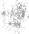
- Figure 1 shows a 3-dimensional plan view of a simplified device 1 for preparing a pineapple fruit A ready for consumption in stationary retail.
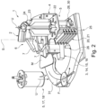
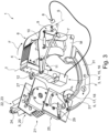
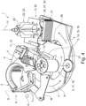
- Figures 2 to 4 show further 3-dimensional views of the device 1 from Figure 1 .
- FIG. 1 Shown in more detail Figures 1 to 4 a device 1 for preparing a pineapple fruit A ready for consumption in a stationary retail outlet.
- the device 1 has a receiving device 2 for receiving a pineapple fruit A in the device 1, a drive 3 with a driver 4 for moving a pineapple fruit A to be processed in the conveying direction F from the receiving device 2 to a cutting device 5, and a cutting device 5 for separating the peel and the stem from edible flesh of the pineapple fruit A.
- the device 1 comprises a device 6 for determining the diameter of the pineapple fruit A in order to minimize waste in the form of peel and stalk in the cutting device 5 and to increase the yield of fruit pulp.
- the device 6 for determining the diameter of the pineapple fruit A has two force-loaded counter-holding elements 7, which are designed as pivoting arms and are subjected to a force acting counter to the conveying direction F. These counter-holding elements 7 also serve, among other things, to straighten or position, for example, a pineapple fruit A inserted at an angle in the device 1 in such a way that the fruit can be optimally processed within the device 1.
- the device 6 for determining the diameter of the pineapple fruit A is designed to determine the path difference between the counter-holder element 7 and the driver 4 from the travel path of the driver 4 in the conveying direction F and the point in time at which the force of the force-loaded counter-holder elements 7 is exceeded by the force of the driver 4 on the pineapple fruit A. This is because the path difference corresponds to the diameter of the pineapple fruit A.
- the device 6 for determining the diameter of the pineapple fruit A has a first sensor 8 for detecting the position of the counter-holding elements 7.
- the first sensor 8 is realized as a contact switch and is designed to detect a predetermined open position and a predetermined closed position of the counter-holder elements 7.
- the device 1 with the first sensor 8 is designed such that a contact signal of the first sensor 8 signals the predetermined open position and a missing contact signal signals the predetermined closed position of the counter-holder elements 7.
- the counter-holding elements 7 are aligned such that the travel path of a pineapple fruit A in the conveying direction F is released by the counter-holding elements 7, wherein in the open position the counter-holding elements 7 are aligned along the conveying direction F of the pineapple fruit A to be processed.
- This can prevent a force acting on the pineapple fruit A to be processed, so that the pineapple fruit A can be moved unhindered by the counter-holding elements 7 in the conveying direction F through the driver 4 to the cutting device 5.
- the counter-holding elements 7 are oriented such that the travel path of a pineapple fruit A in the conveying direction F is blocked by the counter-holding elements 7.
- the counter-holding elements 7 are aligned transversely to the conveying direction F of the pineapple fruit A to be processed in order to generate a maximum force against the conveying direction F of the pineapple fruit A to be processed.
- the device 6 for determining the diameter of the pineapple fruit A has a lever arrangement 9 and a spring force element 10, wherein the lever arrangement 9 and the counter-holding elements 7 are pivotable about a common pivot axis S.
- the lever arrangement 9 has a pivoting part on which the counter-holding elements 7 are arranged, a triangular connecting part on which the spring force element 10, a connecting element 13 and a shaped part for connecting the connecting part to the pivoting part.
- the spring force element 10 is arranged on the lever arrangement 9 in order to counterhold the counterholding elements 7 with a certain force via the pivot axis S. and against the conveying direction F of the pineapple fruit A to be processed.
- the lever arrangement 9 is - as in Figure 3 to be recognized - set up to guide the counter-holding elements 7 from the closed position into the open position and to hold them there as soon as the force acting on the counter-holding elements 7 from the driver 4 via the pineapple fruit A to be processed exceeds the force of the spring force element 10.
- the triangular connecting part of the lever arrangement 9 is pivoted about the pivot part on which the counter-holding elements 7 are arranged, or pivoted about the pivot axis S in such a way that the triangular connecting part contacts the first sensor 8 designed as a contact switch.
- the device 6 for determining the diameter of the pineapple fruit A has a reset mechanism 11 for returning the counter-holding elements 7 from the open position to the closed position.
- the reset mechanism 11 is connected to the lever arrangement 9 in order to return the force-loaded counter-holding elements 7 from the open position to the closed position, whereby a renewed determination of the diameter of a pineapple fruit A can be ensured.
- the return mechanism 11 has a pivoted stop element 12 (mounted like a swing arm on two arms around the axis of rotation T) and a connecting element 13 (in the form of a bent piece of sheet metal) which connects the stop element 12 to the lever arrangement 9.
- the rotation axis T of the stop element 12 and the pivot axis S of the counter-holding elements 7 are oriented in the same way or in the same spatial direction, whereby the connecting element 13 connects the stop element 12 and the counter-holding elements 7 to one another.
- the stop element 12 and the counter-holding elements 7 are further designed such that a rotation of one element simultaneously causes a rotation of the other element in the same direction.
- the connecting element 13 also connects the stop element 12 to the lever arrangement 9 in such a way that by moving the driver 4 back against the conveying direction F and against the stop element 12 the counter-holding elements 7 can be reset from the open position to the closed position.
- the stop element 12 also pivots; namely in the same direction as the counter-holding elements 7 due to the connecting element 13s which connects the stop element 12 to the lever arrangement 9.
- the device 6 for determining the diameter of the pineapple fruit A comprises a second sensor 14 for detecting the position of the driver 4.
- the second sensor 14 is designed to detect the path traveled by the driver 4 of the drive 3 and thus the position of the driver 4.
- the second sensor 14 is arranged on or in the drive 3.
- the second sensor 14 is capable of detecting the relative position of the driver 4 to a predetermined starting position.
- the device 6 for determining the diameter of the pineapple fruit A is designed such that the driver 4 is in the predetermined starting position when the counter-holding elements 7 are arranged in the closed position.
- the device 6 for determining the diameter of the pineapple fruit A can also detect the predetermined starting position of the driver 4 when the first sensor 8 detects the closed position of the counter-holder element 7.
- the device 6 for determining the diameter of the pineapple fruit A is designed such that the driver 4 is arranged in the predetermined starting position when the driver 4 acts against the stop element 16 of the return mechanism 11 and has returned the counter-holding elements 7 from the open position to the closed position.
- the first sensor 8 which is designed as a contact switch, is not contacted.
- the device 6 for determining the diameter of the pineapple fruit A has a determination unit 15 for determining the diameter of the pineapple fruit A.
- the determination unit 15 is connected to the first 8 and the second sensor 14, wherein the determination unit 15 is set up to detect the path covered by the driver 4 in the conveying direction F starting from the predetermined starting position.
- the determination unit 15 is designed such that it stores the predetermined distance between the counter-holder elements 7 and the predetermined starting position of the driver 4.
- the determination unit 15 determines the path traveled by the driver 4 since the starting position from the travel path of the driver 4 in the conveying direction F, which is detected by the second sensor 14, and the point in time, which is detected by the first sensor 8 and at which the force of the force-loaded counter-holder elements 7 acting against the conveying direction F is exceeded by the driver 4.
- the determination unit 15 is able to determine the distance traveled by the driver 4 at the time of a contact signal from the first sensor 8.
- the determination unit 15 is configured to determine the path difference between the counter-holder elements 7 and the driver 4 from the path traveled by the driver 4 and the time at which the first sensor 8 detects the predetermined open position of the counter-holder elements 7.
- This path difference corresponds to the diameter of the pineapple fruit A.
- the determination unit 15 also has the path difference between the path traveled by the driver 4 and the distance of the counter-holder elements 7 to the starting position of the driver 4 stored in a memory.
- the device 6 for determining the diameter of the pineapple fruit A comprises a control unit 16 for controlling the movement of the drive 3.
- control drive 3 such that pineapple fruit A can be placed in cutting device 5 based on the calculated diameter of pineapple fruit A in such a way that waste in the form of peel and stalk can be minimized and the yield of pulp can be maximized.
- control unit 16 it is possible to deactivate the drive 3, in particular as soon as the closed position of the counter-holding elements 7 is detected by the first sensor 8, to move the driver 4 against the conveying direction F or also again in the conveying direction F.
- the cutting device 5 has a separating unit 17 for separating the peel and the stem from edible flesh of the pineapple fruit A.
- the separating unit 17 is equipped with two concentric and circular ring-shaped cutting elements, so that the separating unit 17 is able to create a hollow cylindrical intermediate product from edible pulp of a pineapple fruit A.
- the separating unit 17 has a lifting-movable peeling and coring knife 18 which is designed to remove the stem of a pineapple fruit A as well as to peel the pineapple fruit A and to create a hollow cylindrical intermediate product made of edible pulp.
- the separating unit 18 has an electric lifting drive 19, as in Figure 1 can be seen on which the peeling-coring knife 18 is arranged and with which the peeling-coring knife 18 can be moved.
- the lifting drive 19 makes it possible to move the peeling-coring knife 18 in a separating direction U and also against the separating direction U in order to cut out edible fruit flesh or to release it thereafter.
- the peeling and coring knife 18 has two concentrically arranged cutting elements which are adapted to the size of the pineapple fruit. While the separating unit 18 is located behind the receiving device 2 as seen in the conveying direction F, a portioning unit 20 for portioning ready-to-eat edible fruit pulp is now arranged behind the separating unit 18 as seen in the conveying direction F.
- the portioning unit 20 of the cutting device 5 is designed to portion a hollow cylindrical intermediate product, created by the separating unit 17, by cutting.
- the portioning unit 20 is designed as a cross-cutting unit for cutting slices and as a longitudinal cutting unit for cutting bars and/or pieces. Since in this case slices are always cut first, logically only pieces can be cut from the slices subsequently using the longitudinal cutting unit.
- the portioning unit 20 has a horizontal knife package 21 for cutting slices and a vertical knife package 22 for cutting sticks and/or pieces.
- the cross-cutting unit has a horizontal knife package 21 with various cutting knife elements arranged horizontally one above the other, wherein the cutting knife elements are connected to one another.
- the longitudinal cutting unit is equipped with a vertical knife package 22 with various cutting knife elements arranged next to each other, which are also connected to each other.
- the portioning unit 20 has a lifting-movable stamp unit 23, wherein the cutting knife elements of the longitudinal cutting unit are connected in a star shape to the lifting-movable stamp unit 23.
- the lifting stamp unit 23 has a cylinder element 24 to which the vertical knife package 22 is attached.
- the cylinder element 24 has a diameter which corresponds to the inner diameter of a hollow cylindrical intermediate product produced by the separation unit 17. so that the cylinder element 24 can be countersunk into the inner diameter of the intermediate product.
- the star-shaped cutting blade elements also have a radial length in the radial direction, starting from the cylinder element 24, which exceeds the outer diameter of a hollow cylindrical intermediate product created by the separating unit 17. This ensures that the intermediate product is cut up safely.
- the portioning unit 20 is connected to the electric lifting drive 19, whereby the longitudinal cutting unit can be lifted so that it can be moved by the lifting drive 19 for cutting in the separating direction U and against the separating direction U.
- the cutting device 5 has a pivoting base unit 25 below the cutting knife elements of the longitudinal cutting unit of the portioning unit 20 for releasing a prepared and ready-to-eat portioned pineapple fruit A.
- the swivel base unit 25 comprises an actuating element 26 (see Figure 2 ), a floor element 27 (see Figure 3 ), which has a drop opening 28 (see Figure 1 ) and a spring element 29 (see Figure 3 ), all of which are effectively interconnected.
- the base element 27 is pre-tensioned by the spring element 29 into a first position in which the drop opening 28 is released.
- the driver 4 for guiding a pineapple fruit A now acts from a certain position against the actuating element 26, whereby the base element 27 is moved against the tension force of the spring element 29 into a second position in which the drop opening 28 is closed.
- the base element 27 has a cutting base 30 with notches that are adapted to the arrangement of the cutting elements of the longitudinal cutting unit. This ensures that the hollow cylindrical intermediate product is divided along its entire height without the cutting elements of the longitudinal cutting unit becoming blunt.
- the cutting device 5 is designed to use a top-tail knife, from which in the Figures 1 to 4 only the lower knife M is shown, to cut off the ends of the pineapple fruit A to be processed in the form of end caps.
- the receiving device 2, the cutting device 5 and the device 6 for determining the diameter of the pineapple fruit A are aligned or arranged along a circular path.
- the receiving device 2 and the cutting device 5 and the device 6 for determining the diameter of the pineapple fruit A are arranged along a fruit support 31.
- the fruit support 31 is designed such that the pineapple fruit A, viewed in the conveying direction F, is moved on one level, in particular on a single level, after the device for determining the diameter 6 of the pineapple fruit A to the end of the cutting device 5.
- the device 1 comprises a housing (not shown) which allows a consumer or a purchaser of pineapple pulp in a stationary store to insert and remove the pineapple fruit A.
- the consumer or purchaser is not able to gain further access from the outside using the housing, thus preventing injuries caused by the automated device 1.
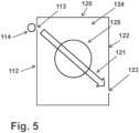
- the system comprises a housing 120 with a rear wall 112 and a front wall 122.
- the housing 120 encloses a processing space 124 in which a device 125 for processing a pineapple is arranged.
- the device 125 is designed analogously to the device 1 explained above for preparing a pineapple fruit A ready for consumption in stationary retail.
- a slot 113 is formed in an upper region, which runs horizontally and extends over more than 50% of the width of the rear wall 112.
- a fan 114 is attached to the rear wall 112 in such a way that it blows air through the slot 113 into the processing chamber 124.
- an air flow 121 is created which flows through the area of the device 125.
- the air flow 121 here runs to a further slot 123, which is arranged in a lower region of a front side 123 of the housing 120.
- the air flow 121 has a strength of at least 150 m 3 /h.
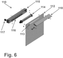
- the ventilated rear wall 110 is designed as an integrated component that can be used as a whole when assembling the housing 120.
- the elements are connected in particular with screws.
- the rear wall 112 is designed as a sheet metal, for example made of stainless steel. In the upper area it has a centrally arranged, horizontal slot 113 which extends over at least 60% of the width of the rear wall 112.
- a fan 114 is mounted on one side of the rear wall 112, which is on the outside when the housing 120 is assembled.
- a low-voltage cross-flow fan is used.
- the fan is covered by a protective cap 115 with air-permeable openings 116 in such a way that reaching into the fan 114 or penetration of larger foreign bodies into the area of the fan 114 from the outside is prevented.
- a switch 117 is provided, which is attached to the protective cap 115 and by means of which the fan 114 can be switched on and off.
- a horizontal air baffle 118 is mounted on the opposite side of the rear wall 112, which is located inside when the housing 120 is assembled. In the example, this is pivotally mounted about a horizontal axis.
- the air baffle 118 runs essentially horizontally and is above the slot 113 of the rear wall 112 in order to deflect the incoming air downwards.
Landscapes
- Life Sciences & Earth Sciences (AREA)
- Engineering & Computer Science (AREA)
- Chemical & Material Sciences (AREA)
- Food Science & Technology (AREA)
- Polymers & Plastics (AREA)
- Forests & Forestry (AREA)
- Mechanical Engineering (AREA)
- Apparatuses For Bulk Treatment Of Fruits And Vegetables And Apparatuses For Preparing Feeds (AREA)
- Preparation Of Fruits And Vegetables (AREA)
- Storage Of Fruits Or Vegetables (AREA)
Priority Applications (1)
| Application Number | Priority Date | Filing Date | Title |
|---|---|---|---|
| EP26155661.7A EP4711106A3 (fr) | 2021-01-20 | 2022-01-11 | Système de préparation prêt à la consommation d'un fruit ananas dans le commerce stationnaire |
Applications Claiming Priority (2)
| Application Number | Priority Date | Filing Date | Title |
|---|---|---|---|
| DE202021100256.5U DE202021100256U1 (de) | 2021-01-20 | 2021-01-20 | System zum verzehrfertigen Aufbereiten einer Ananasfrucht im stationären Handel |
| EP22150825.2A EP4032414B1 (fr) | 2021-01-20 | 2022-01-11 | Système de préparation d'un fruit d'ananas prêt à être consommé dans le commerce traditionnel |
Related Parent Applications (2)
| Application Number | Title | Priority Date | Filing Date |
|---|---|---|---|
| EP22150825.2A Division-Into EP4032414B1 (fr) | 2021-01-20 | 2022-01-11 | Système de préparation d'un fruit d'ananas prêt à être consommé dans le commerce traditionnel |
| EP22150825.2A Division EP4032414B1 (fr) | 2021-01-20 | 2022-01-11 | Système de préparation d'un fruit d'ananas prêt à être consommé dans le commerce traditionnel |
Related Child Applications (1)
| Application Number | Title | Priority Date | Filing Date |
|---|---|---|---|
| EP26155661.7A Division EP4711106A3 (fr) | 2021-01-20 | 2022-01-11 | Système de préparation prêt à la consommation d'un fruit ananas dans le commerce stationnaire |
Publications (2)
| Publication Number | Publication Date |
|---|---|
| EP4484096A2 true EP4484096A2 (fr) | 2025-01-01 |
| EP4484096A3 EP4484096A3 (fr) | 2025-03-05 |
Family
ID=74644848
Family Applications (3)
| Application Number | Title | Priority Date | Filing Date |
|---|---|---|---|
| EP24212844.5A Pending EP4484096A3 (fr) | 2021-01-20 | 2022-01-11 | Système de préparation prêt à la consommation de fruits pendant le commerce stationnaire |
| EP26155661.7A Pending EP4711106A3 (fr) | 2021-01-20 | 2022-01-11 | Système de préparation prêt à la consommation d'un fruit ananas dans le commerce stationnaire |
| EP22150825.2A Active EP4032414B1 (fr) | 2021-01-20 | 2022-01-11 | Système de préparation d'un fruit d'ananas prêt à être consommé dans le commerce traditionnel |
Family Applications After (2)
| Application Number | Title | Priority Date | Filing Date |
|---|---|---|---|
| EP26155661.7A Pending EP4711106A3 (fr) | 2021-01-20 | 2022-01-11 | Système de préparation prêt à la consommation d'un fruit ananas dans le commerce stationnaire |
| EP22150825.2A Active EP4032414B1 (fr) | 2021-01-20 | 2022-01-11 | Système de préparation d'un fruit d'ananas prêt à être consommé dans le commerce traditionnel |
Country Status (2)
| Country | Link |
|---|---|
| EP (3) | EP4484096A3 (fr) |
| DE (1) | DE202021100256U1 (fr) |
Families Citing this family (2)
| Publication number | Priority date | Publication date | Assignee | Title |
|---|---|---|---|---|
| DE202021102887U1 (de) | 2021-05-27 | 2021-06-25 | Hepro Gmbh Maschinen Und Spezialgeräte | Schneidevorrichtung und Schäl- und Entkernungsvorrichtung für eine Ananasfrucht |
| DE202024104015U1 (de) | 2024-07-18 | 2024-08-12 | Tenrit Foodtec Maschinenbau Gmbh | Zitruspresse, insbesondere Orangen- und/oder Zitronenpresse |
Family Cites Families (17)
| Publication number | Priority date | Publication date | Assignee | Title |
|---|---|---|---|---|
| US3561512A (en) * | 1968-04-15 | 1971-02-09 | Ward Foods Inc | Pineapple-treating apparatus |
| AT364478B (de) * | 1980-01-11 | 1981-10-27 | Raunegg Josef | Vorrichtung zum entkernen von kuerbisfruechten |
| US4718333A (en) * | 1986-01-22 | 1988-01-12 | Castle & Cooke, Inc. | Peeling system |
| GB8909480D0 (en) | 1989-04-26 | 1989-06-14 | Williamson Barrie | Vegetable trimmer |
| US6871654B1 (en) | 2002-06-05 | 2005-03-29 | Berke-Tec, Inc., | Fruit and vegetable sonic washer and method |
| FI118917B (sv) * | 2004-09-03 | 2008-05-15 | Norrvik Product Ab Oy | Skalare |
| JP2008220743A (ja) | 2007-03-14 | 2008-09-25 | Sanyo Electric Co Ltd | ショーケース |
| US20110047938A1 (en) | 2009-08-27 | 2011-03-03 | Medina Jose L | Extrusion method and system for packaging segments of a food item |
| GR1008214B (el) | 2013-01-22 | 2014-06-04 | Νικολαος Παναγιωτη Γιαννοπουλος | Ψυγειο βιτρινα αποχυμωτης |
| DE102014013454C5 (de) * | 2014-09-17 | 2024-08-29 | Hepro Gmbh Maschinen Und Spezialgeräte | Verfahren und Vorrichtung zum gefahrlosen Aufbereiten frischer Ananasfrüchte für den Verzehr |
| US20160165947A1 (en) | 2014-12-11 | 2016-06-16 | Mary Ellen Hoye | Fruit and Vegetable Washer |
| CN107692265B (zh) | 2017-10-10 | 2019-11-26 | 永康市简零贸易有限公司 | 一种瓜果去皮装置 |
| CN108244662B (zh) | 2018-01-18 | 2020-03-10 | 平南县正达农业发展有限公司 | 一种龙眼自动去壳脱肉机 |
| JP2019181059A (ja) | 2018-04-17 | 2019-10-24 | 中野冷機株式会社 | 虫除け機能付きオープンショーケース |
| WO2020055232A1 (fr) * | 2018-09-10 | 2020-03-19 | Dutch Food Technology B.V. | Dispositif destiné à la transformation d'ananas |
| DE202018105274U1 (de) * | 2018-09-14 | 2019-01-02 | Hepro Gmbh | Vorrichtung zum verzehrfertigen Aufbereiten einer Ananasfrucht im stationären Handel |
| CN111635840A (zh) | 2020-07-16 | 2020-09-08 | 浙江中亿农业开发有限公司 | 一种猕猴桃果酒蒸馏酒的制作工艺及其设备 |
-
2021
- 2021-01-20 DE DE202021100256.5U patent/DE202021100256U1/de active Active
-
2022
- 2022-01-11 EP EP24212844.5A patent/EP4484096A3/fr active Pending
- 2022-01-11 EP EP26155661.7A patent/EP4711106A3/fr active Pending
- 2022-01-11 EP EP22150825.2A patent/EP4032414B1/fr active Active
Also Published As
| Publication number | Publication date |
|---|---|
| EP4032414B1 (fr) | 2025-04-23 |
| DE202021100256U1 (de) | 2021-02-03 |
| EP4484096A3 (fr) | 2025-03-05 |
| EP4032414C0 (fr) | 2025-04-23 |
| EP4711106A2 (fr) | 2026-03-18 |
| EP4711106A3 (fr) | 2026-06-03 |
| EP4032414A1 (fr) | 2022-07-27 |
Similar Documents
| Publication | Publication Date | Title |
|---|---|---|
| EP4032415B1 (fr) | Dispositif de préparation d'un ananas prêt à être consommé dans le commerce traditionnel | |
| DE69821030T2 (de) | Verfahren und vorrichtung zum braten von kartofellchips | |
| DE3700601C2 (fr) | ||
| EP0793412B1 (fr) | Hache-paille pour broyer la paille derriere les dispositifs de separation des grains d'une moissonneuse batteuse | |
| DE69932724T2 (de) | Ein schneidgerät für küchenmaschinen | |
| EP3420804B1 (fr) | Lame de coupe pour un broyeur de paille | |
| EP4032414B1 (fr) | Système de préparation d'un fruit d'ananas prêt à être consommé dans le commerce traditionnel | |
| EP3182843B1 (fr) | Procede et dispositif pour la production d'un conteneur creux, cylindrique et consommable des fruits ou legumes | |
| EP3829289B1 (fr) | Appareil adaptable pour récolter des cultures céréalières de type tige | |
| CH641006A5 (de) | Schnittgrasfoerdereinrichtung an einem sichelrasenmaeher. | |
| EP1566092B1 (fr) | Dispositif de récolte avec broyeur | |
| DE202012009832U1 (de) | Vorrichtung zur Aufbereitung von Rüben | |
| DE102005059953A1 (de) | Feldhäcksler | |
| DE3727535C2 (de) | Pflückvorrichtung zum Ernten von Halmfrüchten, insbesondere Mais | |
| DE19639805C2 (de) | Mäh- und Fördervorrichtung für stengeliges Erntegut | |
| DE102014011167B4 (de) | Schneidmaschine für strangförmige Lebensmittel | |
| DE102019007585A1 (de) | Reihenunabhängiges Vorsatzgerät zum Ernten stängelförmiger Pflanzen mit einem quer zur Fahrtrichtung liegenden, durch das ganze Vorsatzgerät durchgehenden Pflückspalt | |
| DE20319846U1 (de) | Vorrichtung zur Herstellung von würfelförmigen Produkten in Schneidemaschinen, insbesondere für Käseschneidemaschinen | |
| DE102010006967A1 (de) | Schneidevorrichtung zum Halbieren eines knollenförmigen Lebensmittels und zum gleichzeitigen Schneiden dieser Hälften in verbundene Scheiben | |
| DE3918362A1 (de) | Vorrichtung zum zerkleinern von stengeln einer halmfrucht | |
| EP3651563B1 (fr) | Dispositif permettant d'empêcher toute accumulation de fanes et machine de récolte associée | |
| EP1566091B1 (fr) | Dispositif de récolte avec un hacheur pour tiges | |
| DE927179C (de) | Radial-Foerdergeblaese mit Unfallschutzkruemmer und Einfallmulde | |
| DE102024124064A1 (de) | Horizontalschälmaschine für stangenförmiges Gemüse | |
| DE20006089U1 (de) | Vorrichtung zum Schneiden von dünnen, stangenförmigem Gemüse |
Legal Events
| Date | Code | Title | Description |
|---|---|---|---|
| PUAI | Public reference made under article 153(3) epc to a published international application that has entered the european phase |
Free format text: ORIGINAL CODE: 0009012 |
|
| STAA | Information on the status of an ep patent application or granted ep patent |
Free format text: STATUS: THE APPLICATION HAS BEEN PUBLISHED |
|
| AC | Divisional application: reference to earlier application |
Ref document number: 4032414 Country of ref document: EP Kind code of ref document: P |
|
| AK | Designated contracting states |
Kind code of ref document: A2 Designated state(s): AL AT BE BG CH CY CZ DE DK EE ES FI FR GB GR HR HU IE IS IT LI LT LU LV MC MK MT NL NO PL PT RO RS SE SI SK SM TR |
|
| REG | Reference to a national code |
Ref country code: DE Ref legal event code: R079 Free format text: PREVIOUS MAIN CLASS: B26D0003260000 Ipc: A23N0007000000 |
|
| PUAL | Search report despatched |
Free format text: ORIGINAL CODE: 0009013 |
|
| AK | Designated contracting states |
Kind code of ref document: A3 Designated state(s): AL AT BE BG CH CY CZ DE DK EE ES FI FR GB GR HR HU IE IS IT LI LT LU LV MC MK MT NL NO PL PT RO RS SE SI SK SM TR |
|
| RIC1 | Information provided on ipc code assigned before grant |
Ipc: B26D 3/26 20060101ALI20250130BHEP Ipc: A23N 4/20 20060101ALI20250130BHEP Ipc: A23N 7/00 20060101AFI20250130BHEP |
|
| STAA | Information on the status of an ep patent application or granted ep patent |
Free format text: STATUS: REQUEST FOR EXAMINATION WAS MADE |
|
| 17P | Request for examination filed |
Effective date: 20250805 |