EP4484111A1 - Procédé de fabrication d'un produit en feuille - Google Patents
Procédé de fabrication d'un produit en feuille Download PDFInfo
- Publication number
- EP4484111A1 EP4484111A1 EP23182110.9A EP23182110A EP4484111A1 EP 4484111 A1 EP4484111 A1 EP 4484111A1 EP 23182110 A EP23182110 A EP 23182110A EP 4484111 A1 EP4484111 A1 EP 4484111A1
- Authority
- EP
- European Patent Office
- Prior art keywords
- cylinders
- sheet
- calendering
- coupling
- cylinder
- Prior art date
- Legal status (The legal status is an assumption and is not a legal conclusion. Google has not performed a legal analysis and makes no representation as to the accuracy of the status listed.)
- Pending
Links
Images


Classifications
-
- B—PERFORMING OPERATIONS; TRANSPORTING
- B29—WORKING OF PLASTICS; WORKING OF SUBSTANCES IN A PLASTIC STATE IN GENERAL
- B29C—SHAPING OR JOINING OF PLASTICS; SHAPING OF MATERIAL IN A PLASTIC STATE, NOT OTHERWISE PROVIDED FOR; AFTER-TREATMENT OF THE SHAPED PRODUCTS, e.g. REPAIRING
- B29C43/00—Compression moulding, i.e. applying external pressure to flow the moulding material; Apparatus therefor
- B29C43/32—Component parts, details or accessories; Auxiliary operations
- B29C43/44—Compression means for making articles of indefinite length
- B29C43/46—Rollers
-
- B—PERFORMING OPERATIONS; TRANSPORTING
- B29—WORKING OF PLASTICS; WORKING OF SUBSTANCES IN A PLASTIC STATE IN GENERAL
- B29C—SHAPING OR JOINING OF PLASTICS; SHAPING OF MATERIAL IN A PLASTIC STATE, NOT OTHERWISE PROVIDED FOR; AFTER-TREATMENT OF THE SHAPED PRODUCTS, e.g. REPAIRING
- B29C43/00—Compression moulding, i.e. applying external pressure to flow the moulding material; Apparatus therefor
- B29C43/22—Compression moulding, i.e. applying external pressure to flow the moulding material; Apparatus therefor of articles of indefinite length
- B29C43/24—Calendering
-
- B—PERFORMING OPERATIONS; TRANSPORTING
- B29—WORKING OF PLASTICS; WORKING OF SUBSTANCES IN A PLASTIC STATE IN GENERAL
- B29C—SHAPING OR JOINING OF PLASTICS; SHAPING OF MATERIAL IN A PLASTIC STATE, NOT OTHERWISE PROVIDED FOR; AFTER-TREATMENT OF THE SHAPED PRODUCTS, e.g. REPAIRING
- B29C43/00—Compression moulding, i.e. applying external pressure to flow the moulding material; Apparatus therefor
- B29C43/22—Compression moulding, i.e. applying external pressure to flow the moulding material; Apparatus therefor of articles of indefinite length
- B29C43/30—Making multilayered or multicoloured articles
-
- B—PERFORMING OPERATIONS; TRANSPORTING
- B29—WORKING OF PLASTICS; WORKING OF SUBSTANCES IN A PLASTIC STATE IN GENERAL
- B29C—SHAPING OR JOINING OF PLASTICS; SHAPING OF MATERIAL IN A PLASTIC STATE, NOT OTHERWISE PROVIDED FOR; AFTER-TREATMENT OF THE SHAPED PRODUCTS, e.g. REPAIRING
- B29C43/00—Compression moulding, i.e. applying external pressure to flow the moulding material; Apparatus therefor
- B29C43/32—Component parts, details or accessories; Auxiliary operations
- B29C43/54—Compensating volume change, e.g. retraction
-
- B—PERFORMING OPERATIONS; TRANSPORTING
- B29—WORKING OF PLASTICS; WORKING OF SUBSTANCES IN A PLASTIC STATE IN GENERAL
- B29C—SHAPING OR JOINING OF PLASTICS; SHAPING OF MATERIAL IN A PLASTIC STATE, NOT OTHERWISE PROVIDED FOR; AFTER-TREATMENT OF THE SHAPED PRODUCTS, e.g. REPAIRING
- B29C43/00—Compression moulding, i.e. applying external pressure to flow the moulding material; Apparatus therefor
- B29C43/32—Component parts, details or accessories; Auxiliary operations
- B29C43/44—Compression means for making articles of indefinite length
- B29C43/46—Rollers
- B29C2043/461—Rollers the rollers having specific surface features
-
- B—PERFORMING OPERATIONS; TRANSPORTING
- B29—WORKING OF PLASTICS; WORKING OF SUBSTANCES IN A PLASTIC STATE IN GENERAL
- B29C—SHAPING OR JOINING OF PLASTICS; SHAPING OF MATERIAL IN A PLASTIC STATE, NOT OTHERWISE PROVIDED FOR; AFTER-TREATMENT OF THE SHAPED PRODUCTS, e.g. REPAIRING
- B29C43/00—Compression moulding, i.e. applying external pressure to flow the moulding material; Apparatus therefor
- B29C43/32—Component parts, details or accessories; Auxiliary operations
- B29C43/44—Compression means for making articles of indefinite length
- B29C43/46—Rollers
- B29C2043/467—Rollers plurality of rollers arranged in a specific manner in relation to each other
-
- B—PERFORMING OPERATIONS; TRANSPORTING
- B29—WORKING OF PLASTICS; WORKING OF SUBSTANCES IN A PLASTIC STATE IN GENERAL
- B29C—SHAPING OR JOINING OF PLASTICS; SHAPING OF MATERIAL IN A PLASTIC STATE, NOT OTHERWISE PROVIDED FOR; AFTER-TREATMENT OF THE SHAPED PRODUCTS, e.g. REPAIRING
- B29C43/00—Compression moulding, i.e. applying external pressure to flow the moulding material; Apparatus therefor
- B29C43/22—Compression moulding, i.e. applying external pressure to flow the moulding material; Apparatus therefor of articles of indefinite length
- B29C43/28—Compression moulding, i.e. applying external pressure to flow the moulding material; Apparatus therefor of articles of indefinite length incorporating preformed parts or layers, e.g. compression moulding around inserts or for coating articles
-
- B—PERFORMING OPERATIONS; TRANSPORTING
- B29—WORKING OF PLASTICS; WORKING OF SUBSTANCES IN A PLASTIC STATE IN GENERAL
- B29K—INDEXING SCHEME ASSOCIATED WITH SUBCLASSES B29B, B29C OR B29D, RELATING TO MOULDING MATERIALS OR TO MATERIALS FOR MOULDS, REINFORCEMENTS, FILLERS OR PREFORMED PARTS, e.g. INSERTS
- B29K2027/00—Use of polyvinylhalogenides or derivatives thereof as moulding material
- B29K2027/06—PVC, i.e. polyvinylchloride
-
- B—PERFORMING OPERATIONS; TRANSPORTING
- B29—WORKING OF PLASTICS; WORKING OF SUBSTANCES IN A PLASTIC STATE IN GENERAL
- B29K—INDEXING SCHEME ASSOCIATED WITH SUBCLASSES B29B, B29C OR B29D, RELATING TO MOULDING MATERIALS OR TO MATERIALS FOR MOULDS, REINFORCEMENTS, FILLERS OR PREFORMED PARTS, e.g. INSERTS
- B29K2105/00—Condition, form or state of moulded material or of the material to be shaped
- B29K2105/0005—Condition, form or state of moulded material or of the material to be shaped containing compounding ingredients
-
- B—PERFORMING OPERATIONS; TRANSPORTING
- B29—WORKING OF PLASTICS; WORKING OF SUBSTANCES IN A PLASTIC STATE IN GENERAL
- B29K—INDEXING SCHEME ASSOCIATED WITH SUBCLASSES B29B, B29C OR B29D, RELATING TO MOULDING MATERIALS OR TO MATERIALS FOR MOULDS, REINFORCEMENTS, FILLERS OR PREFORMED PARTS, e.g. INSERTS
- B29K2105/00—Condition, form or state of moulded material or of the material to be shaped
- B29K2105/06—Condition, form or state of moulded material or of the material to be shaped containing reinforcements, fillers or inserts
- B29K2105/08—Condition, form or state of moulded material or of the material to be shaped containing reinforcements, fillers or inserts of continuous length, e.g. cords, rovings, mats, fabrics, strands or yarns
-
- B—PERFORMING OPERATIONS; TRANSPORTING
- B29—WORKING OF PLASTICS; WORKING OF SUBSTANCES IN A PLASTIC STATE IN GENERAL
- B29K—INDEXING SCHEME ASSOCIATED WITH SUBCLASSES B29B, B29C OR B29D, RELATING TO MOULDING MATERIALS OR TO MATERIALS FOR MOULDS, REINFORCEMENTS, FILLERS OR PREFORMED PARTS, e.g. INSERTS
- B29K2105/00—Condition, form or state of moulded material or of the material to be shaped
- B29K2105/06—Condition, form or state of moulded material or of the material to be shaped containing reinforcements, fillers or inserts
- B29K2105/16—Fillers
-
- B—PERFORMING OPERATIONS; TRANSPORTING
- B29—WORKING OF PLASTICS; WORKING OF SUBSTANCES IN A PLASTIC STATE IN GENERAL
- B29K—INDEXING SCHEME ASSOCIATED WITH SUBCLASSES B29B, B29C OR B29D, RELATING TO MOULDING MATERIALS OR TO MATERIALS FOR MOULDS, REINFORCEMENTS, FILLERS OR PREFORMED PARTS, e.g. INSERTS
- B29K2509/00—Use of inorganic materials not provided for in groups B29K2503/00 - B29K2507/00, as filler
-
- B—PERFORMING OPERATIONS; TRANSPORTING
- B29—WORKING OF PLASTICS; WORKING OF SUBSTANCES IN A PLASTIC STATE IN GENERAL
- B29K—INDEXING SCHEME ASSOCIATED WITH SUBCLASSES B29B, B29C OR B29D, RELATING TO MOULDING MATERIALS OR TO MATERIALS FOR MOULDS, REINFORCEMENTS, FILLERS OR PREFORMED PARTS, e.g. INSERTS
- B29K2509/00—Use of inorganic materials not provided for in groups B29K2503/00 - B29K2507/00, as filler
- B29K2509/14—Stones
-
- B—PERFORMING OPERATIONS; TRANSPORTING
- B29—WORKING OF PLASTICS; WORKING OF SUBSTANCES IN A PLASTIC STATE IN GENERAL
- B29L—INDEXING SCHEME ASSOCIATED WITH SUBCLASS B29C, RELATING TO PARTICULAR ARTICLES
- B29L2007/00—Flat articles, e.g. films or sheets
- B29L2007/002—Panels; Plates; Sheets
-
- B—PERFORMING OPERATIONS; TRANSPORTING
- B29—WORKING OF PLASTICS; WORKING OF SUBSTANCES IN A PLASTIC STATE IN GENERAL
- B29L—INDEXING SCHEME ASSOCIATED WITH SUBCLASS B29C, RELATING TO PARTICULAR ARTICLES
- B29L2009/00—Layered products
-
- B—PERFORMING OPERATIONS; TRANSPORTING
- B29—WORKING OF PLASTICS; WORKING OF SUBSTANCES IN A PLASTIC STATE IN GENERAL
- B29L—INDEXING SCHEME ASSOCIATED WITH SUBCLASS B29C, RELATING TO PARTICULAR ARTICLES
- B29L2031/00—Other particular articles
- B29L2031/732—Floor coverings
Definitions
- the invention relates to the production sector of sheet products.
- the invention relates to the production of a semi-finished product comprising two layers of plastic material with possible internal reinforcement layer, of the type usable as base layer for floors.
- sheet product or simply “sheet” indicates a semi-finished product for industrial purposes having a thickness much smaller than the width, typically for example the thickness of a sheet product is few millimeters, while the width can be one or two meters.
- Those products are made in slabs with a discontinuous process or, preferably, in rolls or reels with a continuous process.
- Sheet products are of industrial interest for various applications and can comprise different layers coupled with suitable techniques.
- a sheet product of particular interest, to which the present invention is directed comprises two layers of plastic material coupled together directly or by interposing a central reinforcing layer, for example, of glass fiber.
- the plastic material in question comprises a thermoplastic polymer, for example PVC, mixed with at least one filler material and optionally with additives.
- underlayers for synthetic floors.
- SPC Sonic Polymer Composite
- LVT Luxury Vinyl Tiles
- flooring generally uses a "core" comprising two layers of a plastic material, made with calcium carbonate mixed with PVC powder plus any additives, and optionally a central layer of glass fiber.
- core Above the core, to make the floor, one or more additional layers are applied that can have the function of decoration and protection against wear, UV rays, etc.
- calcium carbonate is used essentially for its low cost and features of stiffness and thermal stability, and can also represent more than 50% of the compound, while the PVC powder is to confer plasticity.
- Additives can be plasticizers and stabilizers; in the lower layer a blowing agent can be used as an additive that gives a certain cushioning capacity to the product.
- the sheets of plastic material are produced by extrusion while the sandwich (that is, the joining of the sheets, possibly with central reinforcement) is made in a press.
- Such process has the disadvantage of being inherently slow.
- the calendering process takes place continuously and is therefore an intrinsically fast process, attractive to increase productivity. SO far however, the calendering process has been deemed unsuitable or not competitive for this specific application.
- the known calendering processes are considered not suitable for the plastic compound sheets considered herein, mainly due to the fact that such sheets have a significant mass and a certain stiffness and tend to warp (for example, by losing flatness) due to cooling. Since a calendering line essentially develops in length, the sheet would be particularly exposed to this problem. One can think of heating the sheet to keep it warm, but this involves a high consumption of energy.
- the invention addresses the problem of how to make by calendering a sheet product of the type used for the core (or base) of LVT and SPC floors, i.e., essentially, a product comprising two layers made of a plastic compound with possible intermediate reinforcing layer.
- the two plastic compound sheets are both obtained by calendering, in two respective groups (calenders) each comprising at least two counter-rotating cylinders.
- the two sheets thus obtained, after detachment from the respective calendering group, are led directly to a further pair of cylinders operating as coupling cylinders and sandwiching directly the two plastic compound sheets, or optionally with the interposition of an intermediate reinforcing layer. Said layer, if present, is separately and individually fed to the two coupling cylinders.
- Both plastic compound sheets pass from the calendering cylinders to the coupling cylinders directly without intermediate process steps. This means for example that the sheets are not heated and do not undergo treatments that modify their physical properties or structure.
- the coupling cylinders are immediately adjacent to the calendering cylinders in order to shorten the path of the sheets.
- said path is the minimum possible, compatible with the overall dimensions of the cylinders and the construction requirements.
- the great advantage of the invention is that it allows the making by a calendering process of a multilayer sheet, of the type that can be used as a base for LVT or SPC, with high productivity and economic advantage over conventional extrusion-based processes.
- a notable feature of the invention is the making of plastic compound sheets by calendering instead of extruding.
- the coupling group proximate to the calendering groups basically allows to carry out the coupling of the compound sheets immediately after detachment from the calendering group (detachment from the output cylinder). In this way, the sheet remains in temperature; it is not necessary to heat it from the outside and it does not undergo deformation (for example, loss of width) due to cooling.
- an object of the invention is a process for making a multilayer material for a synthetic floor, such as an LVT or SPC floor, comprising the steps of making a base layer with the process according to the claims and applying to said base layer one or more additional finishing and/or protective layers.
- the invention also relates to a calendering system according to the claims.
- the invention uses the calendering process which is per se known and does not need to be described in detail. It essentially provides for the passage of the material to be calendered between two counter-rotating cylinders.
- the assembly of the two counter-rotating cylinders is also called calendering group.
- the sheets being of high temperature plastic material, remain adherent to one of the calendering cylinders ("output cylinder").
- output cylinder a detaching cylinder is advantageously provided in the immediate vicinity of the output cylinder.
- the detaching cylinder is placed adjacent to one of the two coupling cylinders, so that each of the two plastic compound sheets, after detachment from the calender, goes directly to the coupling cylinders.
- the invention reduces the temperature drop (delta T) resulting from spontaneous cooling of the sheet while traveling from the calendering group to the coupling group.
- This temperature drop is reduced to substantially negligible values thanks to the close positioning of the cylinders.
- the arrangement of the calendering cylinders and coupling cylinders is such that the temperature difference of the first sheet and of the second sheet between detachment from the calendering cylinders and admission between the coupling cylinders does not exceed the value of 2 degrees °C.
- the sheets of plastic compound can be coupled with or without the addition of an intermediate reinforcing layer. If envisaged, said intermediate layer is fed to the two coupling cylinders individually and separately from the sheets of compound. Preferred materials for the intermediate layer include glass fiber or woven fabric. The passage between the coupling cylinders joins simultaneously the first sheet, the second sheet and the intermediate layer.
- the first compound and the second compound both include PVC or PP as thermoplastic polymer and calcium carbonate as filler material.
- the composition of the two compounds can be the same or different.
- the weight percent of calcium carbonate may be predominant: in preferred applications it is at least 50%, preferably between 50% and 80%, the remainder to 100 being given by the polymer and the additives.
- the percentage of additives is usually about 1%.
- Additives can have various functions such as stabilizer, plasticizer, etc.
- a blowing agent may be used as additive to give cushioning capacity, particularly in the compound used for the bottom layer.
- the first compound and the second compound are fed to the calendering cylinders in the form of a continuous bead of material, which is brought to viscous state and reduced to sheet in the passage between the calendering cylinders.
- the process may include the step of making a polishing or surface finishing or embossing on a surface of the first and/or second plastic compound sheets during the passage between the coupling cylinders.
- One or both the coupling cylinders can have a surface suitably configured for this purpose.
- the coupling cylinders can operate with gap coupling or with pressure coupling.
- first case gap coupling
- second case pressure coupling
- one of the coupling cylinders is pushed against the other and the pressure thus exerted is controlled.
- SPC or LVT type floors An application of considerable industrial interest is represented by SPC or LVT type floors.
- the described calendering and coupling process of plastic compound sheets, optionally with intermediate reinforcement, allows to make the sublayer (also called base layer or "core") of the floor; then, to said base layer one or more finishing layers are applied, such as a printed decorative layer, a wear resistant layer, a UV protective film, or other depending on the product.
- finishing layers such as a printed decorative layer, a wear resistant layer, a UV protective film, or other depending on the product.
- finishing layers such as a printed decorative layer, a wear resistant layer, a UV protective film, or other depending on the product.
- One or more of these further layers can also be applied by calendering.
- the invention can be usefully applied to make technical sheets for tensile structures, membrane covers, vehicle tarpaulins and similar products.
- a calendering system for implementing the process of the invention essentially comprises:
- the two calendering groups and the coupling group are advantageously close together, constituting a single calendering section or island, in order to shorten the path of the plastic compound sheets between calendering and coupling.
- a preferred arrangement of the cylinders is as follows.
- the first pair of calender cylinders and the second pair of calender cylinders comprise each an upper cylinder and a lower cylinder.
- the lower cylinder axis is therefore at a lower height than the upper cylinder axis, even if the axes of said two cylinders are not necessarily vertically aligned.
- the second pair of calendering cylinders is placed at a higher elevation than the first pair, i.e., the axis of the lower cylinder of the second pair is at a higher elevation than the axis of the upper cylinder of the first pair.
- the two coupling cylinders are located at an intermediate elevation between the two pairs of calendering cylinders, that is, at an elevation comprised between the upper cylinder of the first pair and the lower cylinder of the second pair.
- a preferred arrangement of the cylinders satisfies the following conditions: there is at least one vertical plane which intersects at least one cylinder of the first calendering pair and at least one cylinder of the second calendering pair, and furthermore there is at least one vertical plane which intersects both coupling cylinders and at least one of the calendering cylinders.
- the coupling cylinders can operate by controlling the gap space or the pressure exerted against the other cylinder and, consequentially, on the sheets.
- the control is given by one of the two coupling cylinders that is associated with an appropriate positioning system, for example a lever system.
- the position of said cylinder is controlled to keep the gap space constant, and during the operation with pressure coupling the position of said cylinder is controlled to obtain the desired pressure.
- At least one of the two coupling cylinders is movable from the working position to a servicing position in which it is accessible for disassembly and replacement and/or for threading of the intermediate layer.
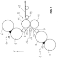
- FIG. 1 shows the following elements:
- the arrow V of Fig. 1 indicates the vertical.
- the two cylinders of the group are of course counter-rotating.
- the cylinders 3 and 5 can be referred to as output cylinders as the plastic compound sheet remains adhered to the surface of the cylinder and is detached with the aid of the cylinders 7 and 8 to be directed towards the coupling group 9.
- the sheets 14 and 15 are obtained as a result of the calendering process of the compound 12, 13 through the respective counter-rotating cylinders. As exemplified in Fig. 1 , the sheets 14, 15 exiting the respective calendering group 1, 4 are led directly between the coupling cylinders 10 and 11.
- Fig. 1 the close position of the coupling unit 9 to the calendering groups.
- the path of sheets 14 and 15 between the detachment from the cylinders 3, 5 and the admission in the coupling cylinders 10, 11 is substantially the minimum required by the overall dimensions of the mechanics. In this way, the sheets 14 and 15 remain in temperature, they do not deform due to cooling and reach group 9 still being in a plastic state which allows the optimal coupling process.
- FIG. 1 also shows the optional inclusion of a reinforcing layer, represented here by the glass fiber 16.
- FIG. 2 Additional features, with reference to a preferred embodiment, are shown in Fig. 2 .
- FIG. 2 shows that the groups 1, 4 and 9 are part of a single calender 20 whose supporting structure is indicated by the reference number 21.
- the figure also shows the feeding of the plastic compound which occurs in the form of a bead 22, 23 which, in Fig. 2 , is visible in cross-section. Said plastic material bead is placed between the cylinders of the calenders 1 and 4, forming the feed material 12, 13 of Fig. 1 .
- one or both the coupling cylinders 10, 11 are movable from the working position to a servicing position in which the cylinder is accessible for disassembly and replacement and/or for threading the intermediate layer.
- FIG. 2 shows with references 10a and 11a the servicing positions of the cylinders 10, 11 respectively.
- the detaching cylinder 7 is associated with the lower coupling cylinder 10 and the detaching cylinder 8 is associated with the upper coupling cylinder 11, therefore the detaching cylinder 7 or 8 moves together with the respective coupling cylinder towards the servicing position 7a, 8a.
- the cylinder 10 or 11 for example is lowered with a suitable mechanized system and extracted with a trolley 24.
- the cylinder 19, which serves as detaching cylinder from group 9, is also preferably movable between a position adjacent to the upper cylinder 11 (as in Fig. 1 ) and a position adjacent to the lower cylinder 10 (position 19a of Fig. 2 ).
- FIG. 2 also shows a preheating section 25 of the glass fiber 16, through two groups of infrared lamps.
- the detaching cylinders 7, 8 and the coupling cylinders 10, 11 are heated, preferably with diathermic oil.
- One or both cylinders 10 or 11 may have a surface suitable for obtaining a desired surface machining or an embossing of the plastic compound sheet 14 or 15, as needed.
- Figs. 1 and 2 show a preferred arrangement in which the calendering group 4 is located at higher elevation than the calendering group 1, while the two coupling cylinders are located at an intermediate elevation.
- the figures show an example of close arrangement of the calendering and coupling groups so that the plastic compound sheets pass directly from the calendering step to the coupling step.
- both the lower calendering group 1 and the coupling group 9 are located, in whole or in part, below the vertical of the upper calendering group 4.
- This can be expressed by observing that there is at least a first vertical plane which intersects at least one cylinder of the first calendering pair 1 and at least one cylinder of the second calendering pair 4 and furthermore there is at least a second vertical plane which intersects both coupling cylinders 10, 11 and at least one of the calendering cylinders.
- said first vertical plane is a vertical plane passing through the center of cylinder 3, which intersects cylinder 5;
- said second vertical plane is a plane passing through the center of the cylinders 10 and 11 which intersects the cylinder 6.
- FIG. 3 shows an example of a product obtainable with the process and machinery of the invention.
- FIG. 3 shows a typical section of a synthetic floor where a base layer 30 consists of the product 18 described above, comprising the sheets 14 and 16 with the glass fiber layer 15 in between. Further layers such as for example a decorated layer 31 (typically with a print that mimics a natural material such as wood), a wear layer 32 and a UV ray protection coating 33, are also shown.
- a decorated layer 31 typically with a print that mimics a natural material such as wood
- a wear layer 32 typically with a UV ray protection coating 33
Landscapes
- Engineering & Computer Science (AREA)
- Mechanical Engineering (AREA)
- Casting Or Compression Moulding Of Plastics Or The Like (AREA)
Priority Applications (1)
| Application Number | Priority Date | Filing Date | Title |
|---|---|---|---|
| EP23182110.9A EP4484111A1 (fr) | 2023-06-28 | 2023-06-28 | Procédé de fabrication d'un produit en feuille |
Applications Claiming Priority (1)
| Application Number | Priority Date | Filing Date | Title |
|---|---|---|---|
| EP23182110.9A EP4484111A1 (fr) | 2023-06-28 | 2023-06-28 | Procédé de fabrication d'un produit en feuille |
Publications (1)
| Publication Number | Publication Date |
|---|---|
| EP4484111A1 true EP4484111A1 (fr) | 2025-01-01 |
Family
ID=87567130
Family Applications (1)
| Application Number | Title | Priority Date | Filing Date |
|---|---|---|---|
| EP23182110.9A Pending EP4484111A1 (fr) | 2023-06-28 | 2023-06-28 | Procédé de fabrication d'un produit en feuille |
Country Status (1)
| Country | Link |
|---|---|
| EP (1) | EP4484111A1 (fr) |
Citations (7)
| Publication number | Priority date | Publication date | Assignee | Title |
|---|---|---|---|---|
| US5911783A (en) * | 1996-06-14 | 1999-06-15 | Hermann Berstorff Maschinenbau Gmbh | Adjusting device for the rolls of a calendar |
| US20050113556A1 (en) * | 2003-11-26 | 2005-05-26 | Strand Marc A. | Polyester compositions for calendering |
| US20090321001A1 (en) * | 2008-06-26 | 2009-12-31 | Seaman Corporation | One-pass direct double lamination apparatus and process |
| JP5626213B2 (ja) * | 2009-09-01 | 2014-11-19 | コニカミノルタ株式会社 | フィルムの製造方法 |
| US20190315103A1 (en) * | 2016-12-01 | 2019-10-17 | Tarkett Gdl S.A. | Floor tile and process for manufacturing thereof |
| US20200331166A1 (en) * | 2017-11-03 | 2020-10-22 | Flooring Industries Limited. Sarl | Method for producing an extruded sheet |
| US20220120095A1 (en) * | 2019-01-09 | 2022-04-21 | Flooring Industries Limited, Sarl | Method for manufacturing a floor or wall panel |
-
2023
- 2023-06-28 EP EP23182110.9A patent/EP4484111A1/fr active Pending
Patent Citations (7)
| Publication number | Priority date | Publication date | Assignee | Title |
|---|---|---|---|---|
| US5911783A (en) * | 1996-06-14 | 1999-06-15 | Hermann Berstorff Maschinenbau Gmbh | Adjusting device for the rolls of a calendar |
| US20050113556A1 (en) * | 2003-11-26 | 2005-05-26 | Strand Marc A. | Polyester compositions for calendering |
| US20090321001A1 (en) * | 2008-06-26 | 2009-12-31 | Seaman Corporation | One-pass direct double lamination apparatus and process |
| JP5626213B2 (ja) * | 2009-09-01 | 2014-11-19 | コニカミノルタ株式会社 | フィルムの製造方法 |
| US20190315103A1 (en) * | 2016-12-01 | 2019-10-17 | Tarkett Gdl S.A. | Floor tile and process for manufacturing thereof |
| US20200331166A1 (en) * | 2017-11-03 | 2020-10-22 | Flooring Industries Limited. Sarl | Method for producing an extruded sheet |
| US20220120095A1 (en) * | 2019-01-09 | 2022-04-21 | Flooring Industries Limited, Sarl | Method for manufacturing a floor or wall panel |
Similar Documents
| Publication | Publication Date | Title |
|---|---|---|
| KR102022210B1 (ko) | 보강 시트를 포함하는 패널의 제조 방법 및 바닥 패널 | |
| US20190315103A1 (en) | Floor tile and process for manufacturing thereof | |
| WO2021056298A1 (fr) | Revêtement de sol en spc à co-extrusion à alignement synchrone en ligne et son procédé de production | |
| CN112793268A (zh) | 一种复合石晶地板及其制造方法 | |
| CN109334180B (zh) | 一种家装用蜂窝复合板及其生产线以及生产工艺 | |
| US20260021617A1 (en) | Device for manufacturing a sheet or panel shaped product and methods for manufacturing a polymeric board or sheet material and/or a decorative panel | |
| KR20180018342A (ko) | 다층 고강도 타일 및 그 제조방법 | |
| EP4484111A1 (fr) | Procédé de fabrication d'un produit en feuille | |
| CN107738394B (zh) | 压延机、发泡地板生产线及一次成型生产工艺 | |
| CN105459422A (zh) | 一次加工pvc地板成型机构 | |
| US10538071B2 (en) | Flooring tile manufacturing apparatus | |
| KR100995452B1 (ko) | 고주파 접착용 열가소성 폴리우레탄 발포 필름의 제조방법 및 상기 방법으로 제조된 열가소성 폴리우레탄 발포 필름 | |
| US12227944B2 (en) | Pre-consolidated fines layer for improved engineered wood products | |
| US20250010512A1 (en) | Methods to provide a floor covering | |
| CN205326316U (zh) | 一次加工pvc地板成型机构 | |
| CN109263218B (zh) | 一种高效隔温防火板材及其生产线以及生产工艺 | |
| CN113002095A (zh) | 一种pvc材质的aba结构地板及生产工艺 | |
| ITTO20080836A1 (it) | Procedimento per l'ottenimento di pannelli decorativi a base di resina termoplastica, impianto per la realizzazione di detto procedimento e pannelli così ottenuti. | |
| KR102511366B1 (ko) | 수증기 투과성 라미나 시트의 제조 방법 및 제조 장치 | |
| US20250269633A9 (en) | Engineered plank and its manufacturing method | |
| LU102788B1 (en) | Wear resistant decorative surface coverings, and process for manufacturing thereof | |
| Rosato | Calendering | |
| CN215882887U (zh) | 一种复合石晶地板 | |
| CN120418086A (zh) | 用于生产地板覆盖物的多层结构 | |
| CA3234216A1 (fr) | Planche d'ingenierie et son procede de fabrication |
Legal Events
| Date | Code | Title | Description |
|---|---|---|---|
| PUAI | Public reference made under article 153(3) epc to a published international application that has entered the european phase |
Free format text: ORIGINAL CODE: 0009012 |
|
| STAA | Information on the status of an ep patent application or granted ep patent |
Free format text: STATUS: THE APPLICATION HAS BEEN PUBLISHED |
|
| AK | Designated contracting states |
Kind code of ref document: A1 Designated state(s): AL AT BE BG CH CY CZ DE DK EE ES FI FR GB GR HR HU IE IS IT LI LT LU LV MC ME MK MT NL NO PL PT RO RS SE SI SK SM TR |
|
| STAA | Information on the status of an ep patent application or granted ep patent |
Free format text: STATUS: REQUEST FOR EXAMINATION WAS MADE |
|
| 17P | Request for examination filed |
Effective date: 20250630 |