EP4484212A2 - Structure de station de charge - Google Patents
Structure de station de charge Download PDFInfo
- Publication number
- EP4484212A2 EP4484212A2 EP24184778.9A EP24184778A EP4484212A2 EP 4484212 A2 EP4484212 A2 EP 4484212A2 EP 24184778 A EP24184778 A EP 24184778A EP 4484212 A2 EP4484212 A2 EP 4484212A2
- Authority
- EP
- European Patent Office
- Prior art keywords
- charging station
- mounting frame
- disposed
- plugging
- socket
- Prior art date
- Legal status (The legal status is an assumption and is not a legal conclusion. Google has not performed a legal analysis and makes no representation as to the accuracy of the status listed.)
- Pending
Links
- 238000000034 method Methods 0.000 claims abstract description 10
- XLYOFNOQVPJJNP-UHFFFAOYSA-N water Substances O XLYOFNOQVPJJNP-UHFFFAOYSA-N 0.000 claims description 7
- 238000009434 installation Methods 0.000 abstract description 16
- 238000007789 sealing Methods 0.000 description 6
- 238000004078 waterproofing Methods 0.000 description 3
- 238000004891 communication Methods 0.000 description 1
- 230000007812 deficiency Effects 0.000 description 1
- 230000000694 effects Effects 0.000 description 1
- 238000011900 installation process Methods 0.000 description 1
- 230000001681 protective effect Effects 0.000 description 1
Images




Classifications
-
- B—PERFORMING OPERATIONS; TRANSPORTING
- B60—VEHICLES IN GENERAL
- B60L—PROPULSION OF ELECTRICALLY-PROPELLED VEHICLES; SUPPLYING ELECTRIC POWER FOR AUXILIARY EQUIPMENT OF ELECTRICALLY-PROPELLED VEHICLES; ELECTRODYNAMIC BRAKE SYSTEMS FOR VEHICLES IN GENERAL; MAGNETIC SUSPENSION OR LEVITATION FOR VEHICLES; MONITORING OPERATING VARIABLES OF ELECTRICALLY-PROPELLED VEHICLES; ELECTRIC SAFETY DEVICES FOR ELECTRICALLY-PROPELLED VEHICLES
- B60L53/00—Methods of charging batteries, specially adapted for electric vehicles; Charging stations or on-board charging equipment therefor; Exchange of energy storage elements in electric vehicles
- B60L53/30—Constructional details of charging stations
- B60L53/31—Charging columns specially adapted for electric vehicles
-
- B—PERFORMING OPERATIONS; TRANSPORTING
- B60—VEHICLES IN GENERAL
- B60L—PROPULSION OF ELECTRICALLY-PROPELLED VEHICLES; SUPPLYING ELECTRIC POWER FOR AUXILIARY EQUIPMENT OF ELECTRICALLY-PROPELLED VEHICLES; ELECTRODYNAMIC BRAKE SYSTEMS FOR VEHICLES IN GENERAL; MAGNETIC SUSPENSION OR LEVITATION FOR VEHICLES; MONITORING OPERATING VARIABLES OF ELECTRICALLY-PROPELLED VEHICLES; ELECTRIC SAFETY DEVICES FOR ELECTRICALLY-PROPELLED VEHICLES
- B60L53/00—Methods of charging batteries, specially adapted for electric vehicles; Charging stations or on-board charging equipment therefor; Exchange of energy storage elements in electric vehicles
- B60L53/10—Methods of charging batteries, specially adapted for electric vehicles; Charging stations or on-board charging equipment therefor; Exchange of energy storage elements in electric vehicles characterised by the energy transfer between the charging station and the vehicle
- B60L53/14—Conductive energy transfer
- B60L53/16—Connectors, e.g. plugs or sockets, specially adapted for charging electric vehicles
-
- B—PERFORMING OPERATIONS; TRANSPORTING
- B60—VEHICLES IN GENERAL
- B60L—PROPULSION OF ELECTRICALLY-PROPELLED VEHICLES; SUPPLYING ELECTRIC POWER FOR AUXILIARY EQUIPMENT OF ELECTRICALLY-PROPELLED VEHICLES; ELECTRODYNAMIC BRAKE SYSTEMS FOR VEHICLES IN GENERAL; MAGNETIC SUSPENSION OR LEVITATION FOR VEHICLES; MONITORING OPERATING VARIABLES OF ELECTRICALLY-PROPELLED VEHICLES; ELECTRIC SAFETY DEVICES FOR ELECTRICALLY-PROPELLED VEHICLES
- B60L53/00—Methods of charging batteries, specially adapted for electric vehicles; Charging stations or on-board charging equipment therefor; Exchange of energy storage elements in electric vehicles
- B60L53/30—Constructional details of charging stations
-
- H—ELECTRICITY
- H01—ELECTRIC ELEMENTS
- H01R—ELECTRICALLY-CONDUCTIVE CONNECTIONS; STRUCTURAL ASSOCIATIONS OF A PLURALITY OF MUTUALLY-INSULATED ELECTRICAL CONNECTING ELEMENTS; COUPLING DEVICES; CURRENT COLLECTORS
- H01R13/00—Details of coupling devices of the kinds covered by groups H01R12/70 or H01R24/00 - H01R33/00
- H01R13/62—Means for facilitating engagement or disengagement of coupling parts or for holding them in engagement
- H01R13/629—Additional means for facilitating engagement or disengagement of coupling parts, e.g. aligning or guiding means, levers, gas pressure electrical locking indicators, manufacturing tolerances
- H01R13/631—Additional means for facilitating engagement or disengagement of coupling parts, e.g. aligning or guiding means, levers, gas pressure electrical locking indicators, manufacturing tolerances for engagement only
-
- H—ELECTRICITY
- H01—ELECTRIC ELEMENTS
- H01R—ELECTRICALLY-CONDUCTIVE CONNECTIONS; STRUCTURAL ASSOCIATIONS OF A PLURALITY OF MUTUALLY-INSULATED ELECTRICAL CONNECTING ELEMENTS; COUPLING DEVICES; CURRENT COLLECTORS
- H01R24/00—Two-part coupling devices, or either of their cooperating parts, characterised by their overall structure
-
- H—ELECTRICITY
- H01—ELECTRIC ELEMENTS
- H01R—ELECTRICALLY-CONDUCTIVE CONNECTIONS; STRUCTURAL ASSOCIATIONS OF A PLURALITY OF MUTUALLY-INSULATED ELECTRICAL CONNECTING ELEMENTS; COUPLING DEVICES; CURRENT COLLECTORS
- H01R31/00—Coupling parts supported only by co-operation with counterpart
- H01R31/06—Intermediate parts for linking two coupling parts, e.g. adapter
-
- H—ELECTRICITY
- H02—GENERATION; CONVERSION OR DISTRIBUTION OF ELECTRIC POWER
- H02G—INSTALLATION OF ELECTRIC CABLES OR LINES, OR OF COMBINED OPTICAL AND ELECTRIC CABLES OR LINES
- H02G3/00—Installations of electric cables or lines or protective tubing therefor in or on buildings, equivalent structures or vehicles
- H02G3/02—Details
- H02G3/08—Distribution boxes; Connection or junction boxes
- H02G3/10—Distribution boxes; Connection or junction boxes for surface mounting on a wall
-
- H—ELECTRICITY
- H01—ELECTRIC ELEMENTS
- H01R—ELECTRICALLY-CONDUCTIVE CONNECTIONS; STRUCTURAL ASSOCIATIONS OF A PLURALITY OF MUTUALLY-INSULATED ELECTRICAL CONNECTING ELEMENTS; COUPLING DEVICES; CURRENT COLLECTORS
- H01R13/00—Details of coupling devices of the kinds covered by groups H01R12/70 or H01R24/00 - H01R33/00
- H01R13/46—Bases; Cases
- H01R13/52—Dustproof, splashproof, drip-proof, waterproof, or flameproof cases
- H01R13/5227—Dustproof, splashproof, drip-proof, waterproof, or flameproof cases with evacuation of penetrating liquids
-
- H—ELECTRICITY
- H01—ELECTRIC ELEMENTS
- H01R—ELECTRICALLY-CONDUCTIVE CONNECTIONS; STRUCTURAL ASSOCIATIONS OF A PLURALITY OF MUTUALLY-INSULATED ELECTRICAL CONNECTING ELEMENTS; COUPLING DEVICES; CURRENT COLLECTORS
- H01R2201/00—Connectors or connections adapted for particular applications
- H01R2201/26—Connectors or connections adapted for particular applications for vehicles
-
- H—ELECTRICITY
- H01—ELECTRIC ELEMENTS
- H01R—ELECTRICALLY-CONDUCTIVE CONNECTIONS; STRUCTURAL ASSOCIATIONS OF A PLURALITY OF MUTUALLY-INSULATED ELECTRICAL CONNECTING ELEMENTS; COUPLING DEVICES; CURRENT COLLECTORS
- H01R24/00—Two-part coupling devices, or either of their cooperating parts, characterised by their overall structure
- H01R24/76—Two-part coupling devices, or either of their cooperating parts, characterised by their overall structure with sockets, clips or analogous contacts and secured to apparatus or structure, e.g. to a wall
-
- H—ELECTRICITY
- H02—GENERATION; CONVERSION OR DISTRIBUTION OF ELECTRIC POWER
- H02G—INSTALLATION OF ELECTRIC CABLES OR LINES, OR OF COMBINED OPTICAL AND ELECTRIC CABLES OR LINES
- H02G3/00—Installations of electric cables or lines or protective tubing therefor in or on buildings, equivalent structures or vehicles
- H02G3/02—Details
- H02G3/08—Distribution boxes; Connection or junction boxes
- H02G3/18—Distribution boxes; Connection or junction boxes providing line outlets
-
- Y—GENERAL TAGGING OF NEW TECHNOLOGICAL DEVELOPMENTS; GENERAL TAGGING OF CROSS-SECTIONAL TECHNOLOGIES SPANNING OVER SEVERAL SECTIONS OF THE IPC; TECHNICAL SUBJECTS COVERED BY FORMER USPC CROSS-REFERENCE ART COLLECTIONS [XRACs] AND DIGESTS
- Y02—TECHNOLOGIES OR APPLICATIONS FOR MITIGATION OR ADAPTATION AGAINST CLIMATE CHANGE
- Y02T—CLIMATE CHANGE MITIGATION TECHNOLOGIES RELATED TO TRANSPORTATION
- Y02T10/00—Road transport of goods or passengers
- Y02T10/60—Other road transportation technologies with climate change mitigation effect
- Y02T10/70—Energy storage systems for electromobility, e.g. batteries
-
- Y—GENERAL TAGGING OF NEW TECHNOLOGICAL DEVELOPMENTS; GENERAL TAGGING OF CROSS-SECTIONAL TECHNOLOGIES SPANNING OVER SEVERAL SECTIONS OF THE IPC; TECHNICAL SUBJECTS COVERED BY FORMER USPC CROSS-REFERENCE ART COLLECTIONS [XRACs] AND DIGESTS
- Y02—TECHNOLOGIES OR APPLICATIONS FOR MITIGATION OR ADAPTATION AGAINST CLIMATE CHANGE
- Y02T—CLIMATE CHANGE MITIGATION TECHNOLOGIES RELATED TO TRANSPORTATION
- Y02T10/00—Road transport of goods or passengers
- Y02T10/60—Other road transportation technologies with climate change mitigation effect
- Y02T10/7072—Electromobility specific charging systems or methods for batteries, ultracapacitors, supercapacitors or double-layer capacitors
Definitions
- the present disclosure relates to the technical field of charging stations, and in particular relates to a charging station structure.
- one comprises inner and outer covers.
- the outer cover is firstly opened, the inner cover is then opened, a wire compartment for wiring is exposed, one comprises a rear cover, and screws are also needed to be removed so as to open the cover for wiring.
- original waterproof performance of the product may be also destroyed if the cover is not properly installed after being opened due to sealing using a sealing ring adopted for waterproofing of the traditional charging stations. That is, in a process of detachment and installation, the screws may be not properly locked, resulting in waterproof failure caused by insufficient sealing distance.
- the main technical problem to be solved by the present disclosure is to provide a charging station structure, which avoids an operation of the user opening a cover and improves installation efficiency.
- the present disclosure provides a charging station structure, and the following technical solution is adapted:
- the plugging and unplugging structure with the upper and lower bodies comprises one or more T-shaped fixing pins disposed on the mounting frame and one or more slots disposed on the charging station body; an end of the one or more slots comprises a U-shaped hole along an installing direction;
- the one or more fixing pins are configured to move up and down in the one or more slots, after the one or more fixing pins are pushed into the one or more slots, the charging station body is pressed to be pushed downward in a vertical direction so as to drive the one or more slots to move until the U-shaped hole is clamped to the one or more fixing pins to form a fixed connection, otherwise the clamping connection and the fixing is released.
- the one or more slots are disposed along one or more edges of an end surface of the accommodating cavity; two sides of the accommodating cavity respectively comprise two of the one or more slots, and one of the one or more slots corresponds to one of the one or more T-shaped fixing pins.
- an anti-detaching member is disposed below the mounting frame, and the anti-detaching member is locked to a bottom of the charging station body.
- two sides of the terminal connector comprise positioning pins
- two sides of the socket correspondingly comprise positioning holes to cooperate with the positioning pins by plugging
- the positioning pins extend along a plugging direction and have a given height difference from the terminal connector.
- a plugging arrangement of the terminal connector and the socket is male and female connectors having opposite plug terminals;
- One of the terminal connector and the socket is a male connector, and another one is a female connector.
- a wire storage slot is disposed in the accommodating cavity at a position corresponding to a commercial power wiring alignment.
- a given gap disposed between the mounting frame and the wire compartment forms a water introduction channel.
- the wire compartment comprises a rear cover, and an upper end of the rear cover comprises a step having a given slope to form a flow introduction structure.
- a low end of the slope of the step is aligned with an end surface of the accommodating cavity.
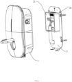
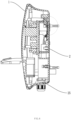
- charging station body 1 accommodating cavity 11; wire storage slot 111; terminal connector 12; positioning pin 121; slot 13; U-shaped hole 14; mounting frame 2; wire compartment 21; positioning holes 211; rear cover 212; flow introduction structure 213; socket 22; commercial power wire hole 23; fixing pin 24; anti-detaching member 25.
- connection can be a wall mountable connection, a detachable connection, or an integrated connection, a mechanical connection, an electrical connection, a direct connection, an indirect connection through an intermediator, or communication between inner portions of two members, for a technical person of ordinary skill in the art, the specific meaning of the terms in the present disclosure can be understood under specific conditions.
- FIGS. 1-8 The present disclosure will be further described below in conjunction with FIGS. 1-8 .
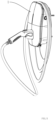
- An embodiment of the present disclosure discloses a charging station structure, and the charging station structure comprises a charging station body 1 and a mounting frame 2, the mounting frame 2 is used to fix to a fixed building; a rear side surface of the charging station body 1 comprises an accommodating cavity 11 having an open style; a terminal connector 12 is disposed in the accommodating cavity 11; a wire compartment 21 is fixedly disposed on the mounting frame 2, and a socket 22 is disposed in the wire compartment 21; the terminal connector 12 is connected to the socket 22 by plugging to achieve power energization, and the wire compartment 21 is disposed in the accommodating cavity 11; the charging station body 1 is fixedly connected to the mounting frame 2 by a clamping structure, and in a clamping state, the terminal connector 12 is maintained to be connected to the socket 22 by plugging simultaneously.
- the charging station structure of the present disclosure does not require opening the cover for wiring and uses the accommodating cavity 11 disposed behind the charging station body and the wire compartment 21 disposed on the mounting frame 2 as a supporting installation, a connection is achieved through plugs of opposite types of the socket 22 and the terminal connector 12, the mounting frame 2, as a whole, can achieve opening and closing of the accommodating cavity 11 of the charging station body, at the same time, the connection of the body and input wires can be realized simultaneously by installing the mounting frame 2 and the accommodating cavity 11, the user can avoid opening the cover due to this design, and the opening of the cover and the wiring are integrated to form a one-step installation, thus improving installation efficiency.
- the charging station body is fixedly connected to the mounting frame by a plugging and unplugging structure with upper and lower bodies, at the same time, a plugging arrangement of a wiring terminal and the socket is male and female connectors having opposite plug terminals, so as to perform a wire connection of a charging station using plugging members having a plugging and unplugging style, which simplifies wiring steps, further, in this embodiment, a plugging and unplugging connection of the terminal connector and the socket is controlled by a plugging and unplugging connection method of the charging station body and the mounting frame, and a connection and a fixation of the mounting frame and a circuit are completed simultaneously through the one-step installation.
- the terminal connector is connected to the socket for power energization using alternating current by plugging, and a convenience of a current connection and a plugging and unplugging installation of the upper and lower bodies is resolved using an application of the male and female connectors in an alternating current charging station.
- the mounting frame 2 comprises a commercial power wiring hole 23 below the wire compartment, and a terminal used for connecting to commercial power in the wire compartment 21 is connected to an external side by the commercial power wiring hole 23; further, a connection structure of the charging station and the commercial power is optimized, a terminal for wiring commercial power moves outwardly from an inner side of the wire compartment 21 to an outer side of the wire compartment 21 so as to realize the connection between the charging station and the commercial power, which can be directly connected to a socket of the terminal through the commercial power wiring hole 23, that is, the commercial power wiring is complete without opening a cover of the charging station body 1.
- a wire storage slot 111 is disposed in the accommodating cavity at a position corresponding to a commercial power wiring alignment, the wire storage slot 111 is designed to extend inward, so that an input wire is not visible from an appearance after the installation is complete.
- the plugging and unplugging structure with the upper and lower bodies comprises T-shaped fixing pins 24 disposed on the mounting frame 2 and slots 13 disposed on the charging station body 1; the slots 13 comprise a U-shaped hole 14 along an installing direction at an end thereof; the fixing pins 24 can move up and down in the slots 13, after the fixing pins 24 have been pushed into the slots 13, the charging station body 1 is pressed to be pushed downward in a vertical direction so as to drive the slots 13 to move until the U-shaped holes 14 are clamped to the fixing pins 24 to form a fixed connection, otherwise the clamping connection and the fixing is released.
- the slots 13 are disposed along an edge of an end face of the accommodating cavity 11; two sides of the accommodating cavity 11 respectively comprise two of the slots 13, and one of the slots 13 corresponds to one of the T-shaped fixing pins 24.
- An arrow defining an installation direction is disposed on the mounting frame 2 and above the wire compartment 21.
- Installation steps of the charging station body 1 and the mounting frame 2 are as follows: in a direction marked by the arrow, the T-shaped fixing pins 24 are firstly aligned with and pushed into the corresponding slots 13, and the charging station body 1 is then pressed down, so that the T-shaped fixing pins 24 are clamped in the U-shaped holes 14, at this time, the terminal connector 12 is connected to the socket 22.
- an anti-detaching member 25 is disposed below the mounting frame 2, the anti-detaching member 25 is locked to a bottom of the charging station body 1, the anti-detaching member 25 comprises a lug structure at the bottom of the mounting frame 2 and a screw, the lug structure is locked to the charging station body 1 by the screw, an anti-detaching screw is designed to further lock the charging station body 1 to the mounting frame 2, thus preventing the charging station body 1 from being removed by someone at random.
- positioning pins 121 are disposed on two sides of the terminal connector 12, and positioning holes 211 are correspondingly disposed on two sides of the socket 22 to cooperate with the positioning pins 121 by plugging.
- the positioning pins 121 extend in a plugging direction and have a given height difference from the terminal connector 12.
- a given gap disposed between the mounting frame 2 and the wire compartment 21 forms a water introduction channel.
- the wire compartment 21 comprises a rear cover 212, and an upper end of the rear cover 212 comprises a step having a given slope to form a flow introduction structure 213.
- a low end of the slope of the step is aligned with an end surface of the accommodating cavity 11, and the rear cover 212 adopts the step with the slope for flow introduction, so that the water flows downward due to gravitational force instead of entering into a shell in a reverse direction, thus achieving waterproofing effects.
- the present disclosure discloses a charging station structure comprising a charging station body and a mounting frame, the mounting frame is configured to be fixed to a fixed building; a rear side surface of the charging station body comprises an accommodating cavity having an open type; a terminal connector is disposed in the accommodating cavity; a wire compartment is fixedly disposed on the mounting frame, and a socket is disposed in the wire compartment; the socket is connected to the terminal connector for power energization by plugging, and the wire compartment is disposed in the accommodating cavity; a commercial power wiring hole is disposed on the mounting frame and below the wire compartment, and a terminal used for connecting to commercial power in the wire compartment is connected to an external side by the commercial power wiring hole; the charging station body is fixedly connected to the mounting frame using a plugging and unplugging structure with upper and lower bodies, a plugging and unplugging connection of the terminal connector and the socket is controlled by a plugging and unplugging connection method of the charging station body and the mounting frame, and the terminal connector is
Landscapes
- Engineering & Computer Science (AREA)
- Power Engineering (AREA)
- Transportation (AREA)
- Mechanical Engineering (AREA)
- Architecture (AREA)
- Civil Engineering (AREA)
- Structural Engineering (AREA)
- Connector Housings Or Holding Contact Members (AREA)
- Charge And Discharge Circuits For Batteries Or The Like (AREA)
Applications Claiming Priority (1)
| Application Number | Priority Date | Filing Date | Title |
|---|---|---|---|
| CN202310776858.6A CN116968573A (zh) | 2023-06-28 | 2023-06-28 | 一种充电桩结构 |
Publications (2)
| Publication Number | Publication Date |
|---|---|
| EP4484212A2 true EP4484212A2 (fr) | 2025-01-01 |
| EP4484212A3 EP4484212A3 (fr) | 2025-04-23 |
Family
ID=88484090
Family Applications (1)
| Application Number | Title | Priority Date | Filing Date |
|---|---|---|---|
| EP24184778.9A Pending EP4484212A3 (fr) | 2023-06-28 | 2024-06-26 | Structure de station de charge |
Country Status (3)
| Country | Link |
|---|---|
| US (1) | US20250001883A1 (fr) |
| EP (1) | EP4484212A3 (fr) |
| CN (1) | CN116968573A (fr) |
Families Citing this family (3)
| Publication number | Priority date | Publication date | Assignee | Title |
|---|---|---|---|---|
| USD1099832S1 (en) * | 2023-09-19 | 2025-10-28 | TOPDON TECHNOLOGY Co., Ltd. | Charging station |
| USD1112051S1 (en) * | 2023-12-14 | 2026-02-10 | Xi'an XYPower Technology Co., Ltd | Charging station |
| USD1113686S1 (en) * | 2023-12-27 | 2026-02-17 | Shenzhen HB electronic co., ltd | Charging station |
Family Cites Families (9)
| Publication number | Priority date | Publication date | Assignee | Title |
|---|---|---|---|---|
| US8006793B2 (en) * | 2008-09-19 | 2011-08-30 | Better Place GmbH | Electric vehicle battery system |
| US9597967B2 (en) * | 2011-07-19 | 2017-03-21 | Siemens Industry, Inc. | Status indicating electric vehicle charging station, lightguide assembly and methods |
| FR3034615B1 (fr) * | 2015-04-01 | 2018-10-26 | Ier | Architecture de borne de rechargement electrique en libre service |
| DE102019114649A1 (de) * | 2019-05-31 | 2020-12-03 | innogy eMobility Solutions GmbH | Ladevorrichtung für Elektrofahrzeuge |
| EP4067159B1 (fr) * | 2021-02-24 | 2024-12-25 | poweersnet GmbH | Station de charge ou station de base pour vehicules electriques |
| WO2022266615A1 (fr) * | 2021-06-15 | 2022-12-22 | GoPowerEV Inc. | Systèmes, procédés et structures de charge associées pour l'installation de sorties électriques |
| CN113937539A (zh) * | 2021-11-09 | 2022-01-14 | 公牛集团股份有限公司 | 一种充电桩 |
| CN219096524U (zh) * | 2023-01-29 | 2023-05-30 | 阳光电源股份有限公司 | 充电桩 |
| CN219133899U (zh) * | 2023-02-14 | 2023-06-06 | 宁波爱立德汽车部件有限公司 | 一种充电桩 |
-
2023
- 2023-06-28 CN CN202310776858.6A patent/CN116968573A/zh active Pending
-
2024
- 2024-06-25 US US18/753,977 patent/US20250001883A1/en active Pending
- 2024-06-26 EP EP24184778.9A patent/EP4484212A3/fr active Pending
Also Published As
| Publication number | Publication date |
|---|---|
| US20250001883A1 (en) | 2025-01-02 |
| CN116968573A (zh) | 2023-10-31 |
| EP4484212A3 (fr) | 2025-04-23 |
Similar Documents
| Publication | Publication Date | Title |
|---|---|---|
| EP4484212A2 (fr) | Structure de station de charge | |
| US12005798B2 (en) | Charging device for electric vehicles | |
| CN113675685B (zh) | 一种轨道插座系统 | |
| WO2023143231A1 (fr) | Connecteur étanche à l'eau à courant élevé basse tension | |
| CN213636436U (zh) | 具有外壳防护的连接器 | |
| WO2000030216A1 (fr) | Connecteur de cables pour panneau solaire | |
| CN218732089U (zh) | 一种新型储能连接器 | |
| CN212784120U (zh) | 一种电动汽车充电插座 | |
| CN219096524U (zh) | 充电桩 | |
| CN209709246U (zh) | 新能源汽车连接器 | |
| CN218334401U (zh) | 一种转换器插座 | |
| CN222191229U (zh) | 一种面板转换器 | |
| CN221379875U (zh) | 一种插拔式公母对插式汽车连接器 | |
| CN216958664U (zh) | 一种防水型电连接器插座 | |
| JP2003197944A (ja) | 端子ボックス | |
| CN215343232U (zh) | 一种电源连接器及供电或耗电设备 | |
| CN219106640U (zh) | 浮动连接器 | |
| CN218750353U (zh) | 一种隔离式电源连接结构及充电桩 | |
| CN217387639U (zh) | 一种具有防开路功能的电连接器 | |
| CN217428074U (zh) | 一种光伏器件接线装置及光伏设备 | |
| CN213878660U (zh) | 多孔插座 | |
| US6872089B1 (en) | Puncturing type cable coupling apparatus | |
| CN217086992U (zh) | 一种高电流高压互锁安全防错连接器 | |
| CN210607864U (zh) | 供电装置及电动自行车 | |
| CN111641091B (zh) | 集成连接器、电池包以及车辆 |
Legal Events
| Date | Code | Title | Description |
|---|---|---|---|
| PUAI | Public reference made under article 153(3) epc to a published international application that has entered the european phase |
Free format text: ORIGINAL CODE: 0009012 |
|
| STAA | Information on the status of an ep patent application or granted ep patent |
Free format text: STATUS: REQUEST FOR EXAMINATION WAS MADE |
|
| 17P | Request for examination filed |
Effective date: 20240627 |
|
| AK | Designated contracting states |
Kind code of ref document: A2 Designated state(s): AL AT BE BG CH CY CZ DE DK EE ES FI FR GB GR HR HU IE IS IT LI LT LU LV MC ME MK MT NL NO PL PT RO RS SE SI SK SM TR |
|
| PUAL | Search report despatched |
Free format text: ORIGINAL CODE: 0009013 |
|
| STAA | Information on the status of an ep patent application or granted ep patent |
Free format text: STATUS: EXAMINATION IS IN PROGRESS |
|
| AK | Designated contracting states |
Kind code of ref document: A3 Designated state(s): AL AT BE BG CH CY CZ DE DK EE ES FI FR GB GR HR HU IE IS IT LI LT LU LV MC ME MK MT NL NO PL PT RO RS SE SI SK SM TR |
|
| RIC1 | Information provided on ipc code assigned before grant |
Ipc: H01R 13/631 20060101ALI20250318BHEP Ipc: B60L 53/16 20190101ALI20250318BHEP Ipc: H05K 7/14 20060101ALI20250318BHEP Ipc: H05K 5/00 20250101ALI20250318BHEP Ipc: H02G 3/10 20060101ALI20250318BHEP Ipc: B60L 53/31 20190101ALI20250318BHEP Ipc: B60L 53/30 20190101AFI20250318BHEP |
|
| 17Q | First examination report despatched |
Effective date: 20250404 |