EP4484228A1 - Sicherheitsgurt-gleitanordnung und fahrzeug - Google Patents
Sicherheitsgurt-gleitanordnung und fahrzeug Download PDFInfo
- Publication number
- EP4484228A1 EP4484228A1 EP23759007.0A EP23759007A EP4484228A1 EP 4484228 A1 EP4484228 A1 EP 4484228A1 EP 23759007 A EP23759007 A EP 23759007A EP 4484228 A1 EP4484228 A1 EP 4484228A1
- Authority
- EP
- European Patent Office
- Prior art keywords
- guide rail
- safety belt
- sliding assembly
- flexible
- flexible section
- Prior art date
- Legal status (The legal status is an assumption and is not a legal conclusion. Google has not performed a legal analysis and makes no representation as to the accuracy of the status listed.)
- Withdrawn
Links
Images






Classifications
-
- B—PERFORMING OPERATIONS; TRANSPORTING
- B60—VEHICLES IN GENERAL
- B60R—VEHICLES, VEHICLE FITTINGS, OR VEHICLE PARTS, NOT OTHERWISE PROVIDED FOR
- B60R22/00—Safety belts or body harnesses in vehicles
- B60R22/18—Anchoring devices
-
- B—PERFORMING OPERATIONS; TRANSPORTING
- B60—VEHICLES IN GENERAL
- B60R—VEHICLES, VEHICLE FITTINGS, OR VEHICLE PARTS, NOT OTHERWISE PROVIDED FOR
- B60R22/00—Safety belts or body harnesses in vehicles
- B60R22/18—Anchoring devices
- B60R22/20—Anchoring devices adjustable in position, e.g. in height
- B60R22/201—Anchoring devices adjustable in position, e.g. in height with the belt anchor connected to a slider movable in a vehicle-mounted track
-
- B—PERFORMING OPERATIONS; TRANSPORTING
- B60—VEHICLES IN GENERAL
- B60R—VEHICLES, VEHICLE FITTINGS, OR VEHICLE PARTS, NOT OTHERWISE PROVIDED FOR
- B60R22/00—Safety belts or body harnesses in vehicles
- B60R22/18—Anchoring devices
- B60R2022/1818—Belt guides
-
- B—PERFORMING OPERATIONS; TRANSPORTING
- B60—VEHICLES IN GENERAL
- B60R—VEHICLES, VEHICLE FITTINGS, OR VEHICLE PARTS, NOT OTHERWISE PROVIDED FOR
- B60R22/00—Safety belts or body harnesses in vehicles
- B60R22/18—Anchoring devices
- B60R2022/1818—Belt guides
- B60R2022/1831—Belt guides comprising a slotted plate sliding in its plane, e.g. inside circular guides
Definitions
- the present disclosure relates to the field of vehicles, and more particularly to a safety belt sliding assembly and a vehicle.
- a safety belt sliding plate is fixed to a back of an upper decorative plate by snapping or other means, and the safety belt sliding plate can slide up and down relative to the upper decorative plate.
- the movement trajectory of the traditional safety belt sliding plate relative to the upper decorative plate is fixed.
- a lower boundary of the sliding plate is higher than a parting between the upper decorative plate and a lower decorative plate/side wall; and when the sliding plate is at a lower limit position, the lower boundary of the sliding plate will be lower than the parting between the upper decorative plate and the lower decorative plate/side wall.
- the two structures When the upper decorative plate is butted with the lower decorative plate or the side wall, the two structures partially overlap at a butt joint, and a thickness of the overlapping part is larger than a thickness of a non-overlapping part.
- a thickness of the overlapping part is larger than a thickness of a non-overlapping part.
- embodiments of the present disclosure are proposed to provide a safety belt sliding assembly and a vehicle that solve the above problems.
- an embodiment of the present disclosure provides a safety belt sliding assembly, which includes: an upper decorative plate having a first surface, in which the first surface is provided with a first guide rail and a second guide rail connected to each other, and the second guide rail is inclined in a direction running away from the first guide rail and in a direction facing away from the first surface; and a sliding plate including a fixed section and a flexible section connected to each other, the fixed section and the flexible section being slidably fitted with the first guide rail, respectively, and the flexible section being configured to slide to the second guide rail and generate deformation.
- the flexible section includes a reinforcing skeleton and a flexible layer connected to each other.
- the reinforcing skeleton is embedded inside the flexible layer.
- the reinforcing skeleton is bonded with the flexible layer; or, the flexible layer is a soft rubber layer, and the reinforcing skeleton is integrated with the flexible layer by injection molding.
- the reinforcing skeleton includes a plurality of reinforcing ribs arranged at intervals along a sliding direction of the sliding plate.
- the flexible section has a first side surface, the first side surface faces away from or faces the first surface, and the first side surface is provided with a deforming groove.
- the first side surface is provided with a plurality of deforming grooves, the plurality of deforming grooves are distributed at intervals along the sliding direction of the sliding plate, a convex portion is formed between adjacent two deforming grooves, the reinforcing ribs of the flexible section are arranged corresponding to the convex portions, and each reinforcing rib corresponds to one convex portion.
- the second guide rail is an arc-shaped guide rail.
- the upper decorative plate has a second surface facing away from the first surface; and the safety belt sliding assembly further includes a lower decorative plate arranged on the second surface, the upper decorative plate has an overlapping area overlapping with the lower decorative plate, the first guide rail is arranged outside the overlapping area, and the second guide rail is arranged in the overlapping area.
- an embodiment of the present disclosure further provides a vehicle, which includes a safety belt sliding assembly
- the safety belt sliding assembly includes: an upper decorative plate having a first surface, in which the first surface is provided with a first guide rail and a second guide rail connected to each other, and the second guide rail is inclined in a direction running away from the first guide rail and in a direction facing away from the first surface; and a sliding plate including a fixed section and a flexible section connected to each other, the fixed section and the flexible section being slidably fitted with the first guide rail, respectively, and the flexible section being configured to slide to the second guide rail and generate deformation.
- the sliding plate is provided with the flexible section, which can achieve flexible deformation.
- a lower end of the sliding plate i.e. the flexible section
- slides to the inclined second guide rail by the deformation of the flexible section itself, it is capable of adapting to switching from the first guide rail to the relatively inclined second guide rail and sliding, thus achieving the change in the movement trajectory of the safety belt sliding plate.
- the flexible section slides on the second guide rail in the direction running away from the first guide rail, the flexible section is gradually inclined inwards relative to the first surface of the upper decorative plate, i.e. moving away from the first surface.
- the inclined second guide rail and the flexible section of the sliding plate are fitted with each other, which can increase the structural space for the sliding of the sliding plate, reduce the appearance surface difference, improve the appearance quality, and increase the design freedom.
- a safety belt sliding plate 20' As shown in Figs. 1 to 5 , the inventor finds in practice that there is a significant surface difference between a safety belt sliding plate 20' and an upper decorative plate 10' in a vehicle, resulting in poor appearance quality.
- the upper decorative plate 10' needs to be butted with other structures such as a lower decorative plate 30' or a side wall, and the two structures partially overlap at a butt joint.
- the lower decorative plate 30' is stacked with the upper decorative plate 10', is arranged on an outer side surface of the upper decorative plate 10', and is arranged adjacent to a lower end of the upper decorative plate 10', so that an upper end of the lower decorative plate 30' and the lower end of the upper decorative plate 10' overlap in an inner-outer direction, and an upper end face of the lower decorative plate 30' serves as a parting line of the two.
- some connecting structures will be arranged between the two, which will also occupy some space.
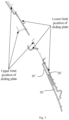
- FIG. 1 An upper limit position of the safety belt sliding plate 20' is shown in Fig. 1 . It can be seen from Fig. 1 that when the safety belt sliding plate 20' is at the upper limit position, a lower boundary of the sliding plate 20' is located above the parting line.
- a lower limit position of the safety belt sliding plate 20' is shown in Fig. 2 . It can be seen from Fig. 2 that when the safety belt sliding plate 20' is at the lower limit position, the lower boundary of the sliding plate 20' is located below the parting line.
- Fig. 3 is a sectional view of the safety belt sliding plate 20' at the upper limit position and at the lower limit position taken along A-A in Fig. 1 . A solid line indicates the lower limit position, and a dashed line indicates the upper limit position.
- trajectories of the sliding plate 20' at the upper limit position and the lower limit position are on the same plane.
- the sliding plate 20' when the lower boundary of the sliding plate 20' is lower than the parting line at the lower limit position, due to limitation of the structural space, in order to avoid interference between the sliding plate 20' and the overlapping part and the connecting structure, the sliding plate 20' needs to be arranged inwards relative to an inner surface of the upper decorative plate 10', which will result in a large surface difference between the sliding plate 20' and the upper decorative plate 10', thus affecting the appearance quality.
- an embodiment of the present disclosure provides a safety belt sliding assembly, which can effectively reduce the surface difference between a sliding plate 20 and an upper decorative plate 10.
- the embodiment of the present disclosure provides the safety belt sliding assembly, which includes the upper decorative plate 10 and the sliding plate 20.
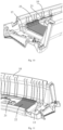
- the upper decorative plate 10 has a first surface 11 and a second surface 12 facing away from each other, the first surface 11 is provided with a first guide rail (not shown in the drawings) and a second guide rail 13 connected to each other, and the second guide rail 13 is inclined in a direction running away from the first guide rail and in a direction facing away from the first surface 11.
- first surface 11 is an inner surface
- second surface 12 is an outer surface.
- the first guide rail and the second guide rail 13 extend in an up-down direction, a lower end of the first guide rail is connected to an upper end of the second guide rail 13, the second guide rail 13 is inclined inwards from top to bottom, the upper end of the second guide rail 13 is adjacent to the first surface 11, and a lower end of the second guide rail 13 is away from the first surface 11.
- the sliding plate 20 includes a fixed section 21 and a flexible section 22 connected to each other.
- the fixed section 21 and the flexible section 22 are slidably fitted with the first guide rail, respectively, and the flexible section 22 is capable of sliding to the second guide rail 13 and generating deformation.
- a lower end of the fixed section 21 is connected to an upper end of the flexible section 22.
- the sliding plate 20 is provided with the flexible section 22, which can achieve flexible deformation.
- a lower end of the sliding plate 20, i.e. the flexible section 22 slides to the inclined second guide rail 13, by the deformation of the flexible section 22 itself, it is capable of adapting to switching from the first guide rail to the relatively inclined second guide rail 13 and sliding, thus achieving the change in the movement trajectory of the safety belt sliding plate 20.
- the flexible section 22 slides on the second guide rail 13 in the direction running away from the first guide rail, the flexible section 22 is gradually inclined inwards relative to the first surface 11 of the upper decorative plate 10, i.e. moving away from the first surface 11.
- the inclined second guide rail 13 and the flexible section 22 of the sliding plate 20 are fitted with each other, which can increase the structural space for the sliding of the sliding plate 20, reduce the appearance surface difference, improve the appearance quality, and increase the design freedom.
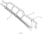
- Fig. 12 is a schematic view showing a state of the sliding plate 20 when it slides to the lower limit position.
- a solid line in Fig. 12 represents the structure of the sliding plate 20 after the trajectory is changed, while a dashed line in Fig. 12 represents the structure of the sliding plate 20 without changing the trajectory by using a traditional guide rail. It can be seen from Fig. 12 that after the second guide rail 13 and the deformable sliding plate 20 of the present disclosure are used, when the sliding plate 20 moves to the lower limit position, the sliding plate 20 can be inclined inwards relative to the first surface 11 to avoid interference, and thus the structural space is more abundant.
- Fig. 14A is a schematic view showing the fit between the sliding plate 20 and the upper decorative plate 10 when the sliding plate 20 according to the embodiment of the present disclosure moves to the lower limit position
- Fig. 14B is a schematic view showing the fit between the sliding plate 20 and the upper decorative plate 10 when the traditional sliding plate 20 moves to the lower limit position. It can be seen from Figs. 14A and 14B that under the premise that the sliding plate 20 and the upper decorative plate 10 have the same surface difference, when the sliding plate 20 with the variable trajectory according to the present disclosure is used, the structural space is more abundant, and the design freedom can be increased.
- the first guide rail may be parallel or roughly parallel to the first surface 11, and the first guide rail may be a straight track.
- the second guide rail 13 may also be a straight track.
- the second guide rail 13 is an arc-shaped guide rail concave to the first surface 11 to form an arc shape.
- the arc-shaped second guide rail 13 is smoothly connected to the first guide rail, and thus it can guide the flexible section 22 to slide smoothly.
- the upper decorative plate 10 adopts a plastic structure
- the first guide rail and the second guide rail 13 may be integrated with the upper decorative plate 10 by injection molding.
- the first guide rail and the second guide rail 13 may also be separately arranged with respect to the upper decorative plate 10, respectively, and then be fixed with the upper decorative plate 10 by snapping or screw connection.
- the sliding plate 20 When the slide plate 20 is at the upper limit position, the sliding plate 20 is fitted with the first guide rail, that is, both the fixed section 21 and the flexible section 22 are fitted with the first guide rail; when the sliding plate 20 moves from the upper limit position to the lower limit position, the sliding plate 20 slides downwards, and the flexible section 22 gradually enters the second guide rail 13, and the fixed section 21 slides on the first guide rail all the time.
- the fixed section 21 may also be made of a flexible material and can generate deformation, so it can slide to the second guide rail 13.
- the flexible section 22 refers to a structure that can generate deformation.
- the materials of the flexible section 22 include, but are not limited to, soft rubber, foam, etc., and the soft rubber may be PS, ABS, AS, PVC, EVA, POE, TPES, or silicone, etc.
- the flexible section 22 When the trajectory of the flexible section 22 changes from the first guide rail to the second guide rail 13, the flexible section 22 generates an elastic deformation to adapt to the second guide rail 13 inclined relative to the first guide rail.
- the flexible section 22 may recover the elastic deformation.
- the flexible section 22 may only include a flexible layer 222.
- the flexible section 22 includes a reinforcing skeleton 221 and the flexible layer 222 connected to each other.
- the flexible layer 222 can generate deformation, and the reinforcing skeleton 221 has an effect of strengthening the structure.
- the flexible layer 222 and the reinforcing skeleton 221 may be stacked, or the reinforcing skeleton 221 is embedded inside the flexible layer 222, so that the flexible layer 222 wraps around the reinforcing skeleton 221.
- the reinforcing skeleton 221 is embedded inside the flexible layer 222.
- the reinforcing skeleton 221 there are various ways to connect the reinforcing skeleton 221 with the flexible layer 222.
- a possible way to fix the reinforcing skeleton 221 with the flexible layer 222 is that the reinforcing skeleton 221 is bonded with the flexible layer 222.
- the reinforcing skeleton 221 and the flexible layer 222 may be bonded by a glue or a double-sided tape.
- the flexible section 22 may have a plurality of flexible layers 222, and the reinforcing skeleton 221 is arranged between adjacent two flexible layers 222, and thus is wrapped inside by the two flexible layers 222.
- the reinforcing skeleton 221 may also be arranged on an outer side surface of the flexible layer 222 and exposed.
- the flexible layer 222 is a soft rubber layer, and the reinforcing skeleton 221 is integrated with the flexible layer 222 by injection molding.
- the flexible layer 222 is injection-molded with plastic cement, and the reinforcing skeleton 221, serving as an insert, is integrated with the flexible layer 222 by injection molding.
- the reinforcing skeleton 221 is embedded inside the flexible layer 222.
- the flexible layer 222 is integrated with the reinforcing skeleton 221 by injection molding, so that there is no need for installation between the flexible layer 222 and the reinforcing skeleton 221, thus avoiding fracture and detachment between the flexible layer 222 and the reinforcing skeleton 221.
- the material of the reinforcing skeleton 221 includes, but is not limited to, the plastic cement or metal.
- the shape of the reinforcing skeleton 221 includes, but is are not limited to, a rod shape, a block shape, a sheet shape, etc.
- the reinforcing skeleton 221 includes a plurality of reinforcing ribs arranged at intervals along a sliding direction of the sliding plate 20. Since there is an interval between adjacent two reinforcing ribs, the interval is equivalent to providing a certain deformation space for the flexible section 22, ensuring that the flexible section 22 is capable of being smoothly deformed and realizing smooth sliding when butted with the second guide rail 13.
- the plurality of reinforcing ribs may also play a structure strengthening role for the flexible layer 222, thus preventing the flexible layer 222 from being excessively deformed and hence detached from the first guide rail or the second guide rail 13 due to its softer material.
- the flexible section 22 has a first side surface 201 extending along the sliding direction of the sliding plate 20, and the first side surface 201 faces away from or faces the first surface 11.
- the first side surface 201 is provided with a deforming groove 202 that may provide a deformation space for the flexible section 22 when the flexible section 22 generates deformation, thus preventing the flexible section 22 from being twisted and detached from the second guide rail 13.
- the shape of the deforming groove 202 includes, but is not limited to, an elongated shape, a circle shape, an ellipse shape, a triangle shape, a square shape, etc.
- One or more deforming grooves 202 may be provided. When a plurality of deforming grooves 202 are provided, the plurality of deforming grooves 202 may be distributed at intervals along the sliding direction of the sliding plate 20, or the plurality of deforming grooves 202 may be arranged in a rectangular array, etc.
- the plurality of deforming grooves 202 are distributed at intervals along the sliding direction of the sliding plate 20, and a convex portion 203 is formed between adjacent two deforming grooves 202, so that a plurality of convex portions 203 arranged at intervals are formed along the sliding direction of the sliding plate 20.
- the convex portion 203 is in a shape of a long strip, and has a length direction perpendicular to the sliding direction.
- the reinforcing ribs of the flexible section 22 are arranged corresponding to the convex portions 203, and each of the reinforcing ribs corresponds to one convex portion 203.
- a wall thickness of the convex portion 203 is larger, and thus the reinforcing rib may be better wrapped.
- the deforming grooves 202 on two sides of the convex portion 203 may provide a certain deformation space for the flexible section 22, and when the flexible section 22 is extruded, a distance between adjacent two convex portions 203 may be compressed and reduced.
- the fixed section 21 is integrated with the flexible section 22 by injection molding.
- the fixed section 21 may adopt a rigid plastic cement structure
- the flexible layer 222 of the flexible section 22 adopts a soft plastic cement structure
- the two are integrated by injection molding.
- the fixed section 21 and the flexible section 22 may also be fixed by means of insertion, buckle connection, screw connection, bonding, etc.
- the shapes of the fixed section 21 and the flexible section 22 include, but are not limited to, a shape of a long strip plate or a square plate.
- the fixed section 21 is in a shape of a rectangular plate, and has a length direction along the sliding direction
- the flexible section 22 is in a shape of a rectangular plate, and has a length direction perpendicular to the sliding direction, and a width direction along the sliding direction.
- two tracks may be arranged corresponding to the sliding plate 20.
- the two tracks are arranged at intervals in a direction perpendicular to the sliding direction, and each of the two tracks includes the first guide rail and the second guide rail 13.
- the sliding plate 20 may also be provided with a sliding groove 204 to be butted with the track.
- the safety belt sliding assembly further includes a lower decorative plate 30 arranged on the second surface 12, the upper decorative plate 10 has an overlapping area overlapping with the lower decorative plate 30, the first guide rail is arranged outside the overlapping area, and the second guide rail 13 is arranged in the overlapping area.
- the second guide rail 13 By arranging the second guide rail 13 in the overlapping area, when the sliding plate 20 slides to the overlapping area, it is capable of sliding in a direction away running from the first surface 11, so as to avoid interference with the overlapping area, thus increasing the sliding space of the sliding plate 20.
- An embodiment of the present disclosure further provides a vehicle, which includes a safety belt sliding assembly, and a sliding plate 20 of the safety belt sliding assembly is connected with a safety belt.
- a vehicle which includes a safety belt sliding assembly, and a sliding plate 20 of the safety belt sliding assembly is connected with a safety belt.
- the specific structure of the safety belt sliding assembly is referred to the above embodiments, and is not repeated here.
Landscapes
- Engineering & Computer Science (AREA)
- Mechanical Engineering (AREA)
- Automotive Seat Belt Assembly (AREA)
- Support Devices For Sliding Doors (AREA)
- Vehicle Interior And Exterior Ornaments, Soundproofing, And Insulation (AREA)
Applications Claiming Priority (2)
| Application Number | Priority Date | Filing Date | Title |
|---|---|---|---|
| CN202220373648.3U CN217396473U (zh) | 2022-02-23 | 2022-02-23 | 安全带滑动组件和车辆 |
| PCT/CN2023/074812 WO2023160382A1 (zh) | 2022-02-23 | 2023-02-07 | 安全带滑动组件和车辆 |
Publications (2)
| Publication Number | Publication Date |
|---|---|
| EP4484228A1 true EP4484228A1 (de) | 2025-01-01 |
| EP4484228A4 EP4484228A4 (de) | 2025-05-07 |
Family
ID=83136758
Family Applications (1)
| Application Number | Title | Priority Date | Filing Date |
|---|---|---|---|
| EP23759007.0A Withdrawn EP4484228A4 (de) | 2022-02-23 | 2023-02-07 | Sicherheitsgurt-gleitanordnung und fahrzeug |
Country Status (4)
| Country | Link |
|---|---|
| US (1) | US20250162534A1 (de) |
| EP (1) | EP4484228A4 (de) |
| CN (1) | CN217396473U (de) |
| WO (1) | WO2023160382A1 (de) |
Families Citing this family (1)
| Publication number | Priority date | Publication date | Assignee | Title |
|---|---|---|---|---|
| CN217396473U (zh) * | 2022-02-23 | 2022-09-09 | 北京车和家汽车科技有限公司 | 安全带滑动组件和车辆 |
Family Cites Families (20)
| Publication number | Priority date | Publication date | Assignee | Title |
|---|---|---|---|---|
| JP2913801B2 (ja) * | 1990-09-05 | 1999-06-28 | タカタ株式会社 | ショルダーアジャスタ |
| JPH0653329U (ja) * | 1993-01-06 | 1994-07-19 | 河西工業株式会社 | スライドプレートの構造 |
| JP3665233B2 (ja) * | 1999-08-02 | 2005-06-29 | 株式会社東海理化電機製作所 | 緩衝部材及びショルダアンカ高さ調節装置 |
| JP4171143B2 (ja) * | 1999-08-31 | 2008-10-22 | 日本プラスト株式会社 | ピラーガーニッシュ |
| KR20030079129A (ko) * | 2002-04-02 | 2003-10-10 | 유겐가이샤 소고 오리지날 크리에이트 | 시트벨트 스톱퍼 및 그 어태치먼트 |
| US9199599B2 (en) * | 2012-01-11 | 2015-12-01 | Takata Corporation | Passenger protection device |
| JP5895708B2 (ja) * | 2012-05-25 | 2016-03-30 | スズキ株式会社 | ピラートリム構造 |
| FR3000446B1 (fr) * | 2012-12-27 | 2016-01-01 | Faurecia Interieur Ind | Element interieur de vehicule avec rideau souple recouvert de bois |
| US8991866B2 (en) * | 2013-06-17 | 2015-03-31 | Nissan North America, Inc. | Vehicle pillar trim assembly |
| CN204055704U (zh) * | 2014-07-18 | 2014-12-31 | 北京汽车研究总院有限公司 | 一种车用安全带高度调节装置及汽车 |
| CN206537251U (zh) * | 2017-02-27 | 2017-10-03 | 长城汽车股份有限公司 | 安全带的调节板按钮结构及车辆 |
| JP6855996B2 (ja) * | 2017-10-10 | 2021-04-07 | トヨタ自動車株式会社 | 車両用乗員拘束装置 |
| CN207481798U (zh) * | 2017-11-07 | 2018-06-12 | 蔚来汽车有限公司 | 车辆立柱内饰板和车辆 |
| US10493949B2 (en) * | 2017-11-09 | 2019-12-03 | Ford Global Technologies, Llc | Seatbelt assembly |
| CN209938525U (zh) * | 2019-04-16 | 2020-01-14 | 沈阳金杯锦恒汽车安全系统有限公司 | 一种安全带高度调节器 |
| CN212325707U (zh) * | 2020-07-19 | 2021-01-12 | 温州市鹏帆箱包配件有限公司 | 带储物盒的拉杆箱 |
| CN112918396B (zh) * | 2021-04-02 | 2025-03-18 | 蔚来汽车科技(安徽)有限公司 | 车辆立柱的内饰板及车辆 |
| CN113153118A (zh) * | 2021-04-21 | 2021-07-23 | 青岛华涛汽车模具有限公司 | 一种汽车储物盒卷帘门 |
| CN217396473U (zh) * | 2022-02-23 | 2022-09-09 | 北京车和家汽车科技有限公司 | 安全带滑动组件和车辆 |
| DE102023004664A1 (de) * | 2022-11-25 | 2024-05-29 | Mercedes-Benz Group AG | Gurthöhenverstellungssystem für Fahrzeuge |
-
2022
- 2022-02-23 CN CN202220373648.3U patent/CN217396473U/zh active Active
-
2023
- 2023-02-07 WO PCT/CN2023/074812 patent/WO2023160382A1/zh not_active Ceased
- 2023-02-07 EP EP23759007.0A patent/EP4484228A4/de not_active Withdrawn
- 2023-02-07 US US18/840,654 patent/US20250162534A1/en not_active Abandoned
Also Published As
| Publication number | Publication date |
|---|---|
| EP4484228A4 (de) | 2025-05-07 |
| CN217396473U (zh) | 2022-09-09 |
| US20250162534A1 (en) | 2025-05-22 |
| WO2023160382A1 (zh) | 2023-08-31 |
Similar Documents
| Publication | Publication Date | Title |
|---|---|---|
| KR101269016B1 (ko) | 적어도 2개의 인접한 유리 성분으로 구성된 복합 칸막이 유리와, 상기 복합 칸막이 유리를 제조하는 방법 | |
| EP4484228A1 (de) | Sicherheitsgurt-gleitanordnung und fahrzeug | |
| EP3604966A1 (de) | Gehäuse und wandmontierte klimaanlage | |
| EP3395595B1 (de) | Fensterstruktur für ein kraftfahrzeug und kraftfahrzeug | |
| CN118514493B (zh) | 集成导轨的玻璃总成及车辆 | |
| CN219277217U (zh) | 车门三角窗一侧的呢槽安装结构及车门 | |
| CN112634765A (zh) | 大曲率显示面板及显示装置 | |
| JPH0645299B2 (ja) | ウインドウモ−ルデイングおよびその製造方法 | |
| CN221113471U (zh) | 车门的玻璃滑块及车门、车辆 | |
| US20250346192A1 (en) | Sunroof glass assembly, vehicles, and luggage carrier | |
| CN210564168U (zh) | 活芯高分子面板的门扇 | |
| JP2885818B2 (ja) | サッシュレスドア型車のウエザーストリップ | |
| CN222832230U (zh) | 一种多片式玻璃总成 | |
| CN222863825U (zh) | 销、天窗组件及车辆 | |
| JPH0336699Y2 (de) | ||
| CN119777549A (zh) | 墙板安装构件 | |
| CN222478512U (zh) | 一种压扣式柜门 | |
| CN215321953U (zh) | 一种汽车天窗密封条及其连接结构 | |
| CN223241805U (zh) | 一种拼装式pvc型材 | |
| CN224028786U (zh) | 饰条总成及车辆 | |
| CN217153898U (zh) | 一种线形灯不漏光端部结构及线形灯 | |
| CN221969343U (zh) | 车辆的三角窗总成和车辆 | |
| JP2738519B2 (ja) | 断熱パネル | |
| CN222109810U (zh) | 一种新型窗帘导轨 | |
| CN221457157U (zh) | 一种副屏组件及智慧黑板 |
Legal Events
| Date | Code | Title | Description |
|---|---|---|---|
| STAA | Information on the status of an ep patent application or granted ep patent |
Free format text: STATUS: THE INTERNATIONAL PUBLICATION HAS BEEN MADE |
|
| PUAI | Public reference made under article 153(3) epc to a published international application that has entered the european phase |
Free format text: ORIGINAL CODE: 0009012 |
|
| STAA | Information on the status of an ep patent application or granted ep patent |
Free format text: STATUS: REQUEST FOR EXAMINATION WAS MADE |
|
| 17P | Request for examination filed |
Effective date: 20240828 |
|
| AK | Designated contracting states |
Kind code of ref document: A1 Designated state(s): AL AT BE BG CH CY CZ DE DK EE ES FI FR GB GR HR HU IE IS IT LI LT LU LV MC ME MK MT NL NO PL PT RO RS SE SI SK SM TR |
|
| A4 | Supplementary search report drawn up and despatched |
Effective date: 20250404 |
|
| RIC1 | Information provided on ipc code assigned before grant |
Ipc: B60R 22/20 20060101ALI20250331BHEP Ipc: B60R 22/24 20060101AFI20250331BHEP |
|
| DAV | Request for validation of the european patent (deleted) | ||
| DAX | Request for extension of the european patent (deleted) | ||
| STAA | Information on the status of an ep patent application or granted ep patent |
Free format text: STATUS: EXAMINATION IS IN PROGRESS |
|
| 17Q | First examination report despatched |
Effective date: 20251009 |
|
| STAA | Information on the status of an ep patent application or granted ep patent |
Free format text: STATUS: THE APPLICATION HAS BEEN WITHDRAWN |
|
| 18W | Application withdrawn |
Effective date: 20260107 |