EP4484231A1 - Procédé de commande autonome d'un système de freinage d'un véhicule tracté d'un semi-remorque - Google Patents
Procédé de commande autonome d'un système de freinage d'un véhicule tracté d'un semi-remorque Download PDFInfo
- Publication number
- EP4484231A1 EP4484231A1 EP24179016.1A EP24179016A EP4484231A1 EP 4484231 A1 EP4484231 A1 EP 4484231A1 EP 24179016 A EP24179016 A EP 24179016A EP 4484231 A1 EP4484231 A1 EP 4484231A1
- Authority
- EP
- European Patent Office
- Prior art keywords
- trailer vehicle
- vehicle
- braking
- hor
- force
- Prior art date
- Legal status (The legal status is an assumption and is not a legal conclusion. Google has not performed a legal analysis and makes no representation as to the accuracy of the status listed.)
- Granted
Links
Images


Classifications
-
- B—PERFORMING OPERATIONS; TRANSPORTING
- B60—VEHICLES IN GENERAL
- B60T—VEHICLE BRAKE CONTROL SYSTEMS OR PARTS THEREOF; BRAKE CONTROL SYSTEMS OR PARTS THEREOF, IN GENERAL; ARRANGEMENT OF BRAKING ELEMENTS ON VEHICLES IN GENERAL; PORTABLE DEVICES FOR PREVENTING UNWANTED MOVEMENT OF VEHICLES; VEHICLE MODIFICATIONS TO FACILITATE COOLING OF BRAKES
- B60T13/00—Transmitting braking action from initiating means to ultimate brake actuator with power assistance or drive; Brake systems incorporating such transmitting means, e.g. air-pressure brake systems
- B60T13/02—Transmitting braking action from initiating means to ultimate brake actuator with power assistance or drive; Brake systems incorporating such transmitting means, e.g. air-pressure brake systems with mechanical assistance or drive
- B60T13/06—Transmitting braking action from initiating means to ultimate brake actuator with power assistance or drive; Brake systems incorporating such transmitting means, e.g. air-pressure brake systems with mechanical assistance or drive by inertia, e.g. flywheel
- B60T13/08—Overrun brakes
-
- B—PERFORMING OPERATIONS; TRANSPORTING
- B60—VEHICLES IN GENERAL
- B60T—VEHICLE BRAKE CONTROL SYSTEMS OR PARTS THEREOF; BRAKE CONTROL SYSTEMS OR PARTS THEREOF, IN GENERAL; ARRANGEMENT OF BRAKING ELEMENTS ON VEHICLES IN GENERAL; PORTABLE DEVICES FOR PREVENTING UNWANTED MOVEMENT OF VEHICLES; VEHICLE MODIFICATIONS TO FACILITATE COOLING OF BRAKES
- B60T13/00—Transmitting braking action from initiating means to ultimate brake actuator with power assistance or drive; Brake systems incorporating such transmitting means, e.g. air-pressure brake systems
- B60T13/10—Transmitting braking action from initiating means to ultimate brake actuator with power assistance or drive; Brake systems incorporating such transmitting means, e.g. air-pressure brake systems with fluid assistance, drive, or release
- B60T13/24—Transmitting braking action from initiating means to ultimate brake actuator with power assistance or drive; Brake systems incorporating such transmitting means, e.g. air-pressure brake systems with fluid assistance, drive, or release the fluid being gaseous
- B60T13/26—Compressed-air systems
- B60T13/261—Compressed-air systems systems with both indirect application and application by springs or weights and released by compressed air
- B60T13/265—Compressed-air systems systems with both indirect application and application by springs or weights and released by compressed air dependent systems, e.g. trailer systems
-
- B—PERFORMING OPERATIONS; TRANSPORTING
- B60—VEHICLES IN GENERAL
- B60T—VEHICLE BRAKE CONTROL SYSTEMS OR PARTS THEREOF; BRAKE CONTROL SYSTEMS OR PARTS THEREOF, IN GENERAL; ARRANGEMENT OF BRAKING ELEMENTS ON VEHICLES IN GENERAL; PORTABLE DEVICES FOR PREVENTING UNWANTED MOVEMENT OF VEHICLES; VEHICLE MODIFICATIONS TO FACILITATE COOLING OF BRAKES
- B60T7/00—Brake-action initiating means
- B60T7/12—Brake-action initiating means for automatic initiation; for initiation not subject to will of driver or passenger
- B60T7/20—Brake-action initiating means for automatic initiation; for initiation not subject to will of driver or passenger specially for trailers, e.g. in case of uncoupling of or overrunning by trailer
-
- B—PERFORMING OPERATIONS; TRANSPORTING
- B60—VEHICLES IN GENERAL
- B60T—VEHICLE BRAKE CONTROL SYSTEMS OR PARTS THEREOF; BRAKE CONTROL SYSTEMS OR PARTS THEREOF, IN GENERAL; ARRANGEMENT OF BRAKING ELEMENTS ON VEHICLES IN GENERAL; PORTABLE DEVICES FOR PREVENTING UNWANTED MOVEMENT OF VEHICLES; VEHICLE MODIFICATIONS TO FACILITATE COOLING OF BRAKES
- B60T8/00—Arrangements for adjusting wheel-braking force to meet varying vehicular or ground-surface conditions, e.g. limiting or varying distribution of braking force
- B60T8/17—Using electrical or electronic regulation means to control braking
- B60T8/1701—Braking or traction control means specially adapted for particular types of vehicles
- B60T8/1708—Braking or traction control means specially adapted for particular types of vehicles for lorries or tractor-trailer combinations
Definitions
- the invention relates to a method for the autonomous control of a braking system of a trailer vehicle of a semitrailer truck.
- a method for electronic coupling force control in multi-part vehicles is known in which a force between the towing vehicle and the trailer vehicle in the direction of travel is measured in a fifth wheel coupling and a transverse force component between the towing vehicle and the trailer vehicle is determined from this.
- a pressure force sensor is arranged on the fifth wheel coupling to determine this force in the longitudinal direction. The pressure force is an indication that the trailer vehicle is driving into the towing vehicle and must be braked. The braking requirement in the towing vehicle for the trailer vehicle is determined from the forces determined in this way.
- This task is solved by a method for the autonomous control of a braking system of a trailer vehicle of a semitrailer, in which a force of the trailer vehicle acting on a kingpin is determined.
- a braking signal is determined for setting a braking force in the trailer vehicle, wherein the braking force is set in such a way that a resulting braking of the trailer vehicle corresponds to a quotient of the horizontal force acting on the kingpin and a support load acting on a fifth wheel plate of a fifth wheel coupling.
- the braking force for the trailer vehicle is calculated independently of the towing vehicle and thus enables autonomous control of the trailer vehicle's braking system. This prevents dangerous situations if electrical and/or pneumatic control lines that connect the towing vehicle to the trailer vehicle fail or are interrupted.
- the trailer vehicle is always able to brake independently without installing additional electrical and/or pneumatic control lines between the towing vehicle and the trailer vehicle. Even in the case of vehicle systems in which the braking request is transmitted wirelessly, for example via radio, from the towing vehicle to the trailer vehicle, the trailer vehicle can be braked at any time if the wireless communication fails or is disrupted.
- the trailer vehicles can be appropriately equipped so that they can be operated safely on public roads in the event of any failures or problems with the vehicle combination.
- Each axle of the trailer brakes the mass resting on it. This means that the calculated quotient of braking force and axle load is the same on all axles, including the fifth wheel plate of the towing vehicle.
- the vehicle combination brakes, the part of the trailer's mass that rests on the fifth wheel plate is also braked by the towing vehicle.
- the horizontal force between the towing vehicle and the trailer vehicle of the vehicle combination is measured, from which the proportion of the trailer's mass that is braked by the towing vehicle and not by the trailer vehicle is determined.
- the static support load which represents a vertical force
- the static support load is determined on the fifth wheel plate from a total mass of the towing vehicle minus an axle load of the trailer vehicle. To improve the accuracy of the measured support load, this is reduced or increased depending on rolling resistance and/or any downhill force. The calculation is carried out continuously while the trailer vehicle is accelerating and is saved for use during braking.
- the quotient of horizontal force and support load is calculated when the towing vehicle is braking and, depending on the currently determined quotient, a target deceleration is set up with the braking system as a braking signal, which is determined by comparing the currently determined quotient with a threshold value.
- This target deceleration represents a valid braking signal with which the trailer vehicle can brake itself.
- the target deceleration of the trailer vehicle is reduced if the currently determined quotient is smaller than the threshold value.
- the target deceleration of the trailer vehicle is increased if the currently determined quotient is larger than the threshold value.
- the reduction and/or increase of the target deceleration can be carried out by a percentage value, for example by a value from the range between 0.5% and 2%, in particular by a value from the range between 0.7% and 1.3%, in particular by 1% or by 2%. If the currently determined quotient corresponds to the target value, the trailer vehicle is braked optimally.
- a brake pressure generated in the braking system of the trailer vehicle is controlled according to the current target deceleration and corrected during the braking process of the trailer vehicle according to the currently determined quotient in a tolerance band.
- the width of the tolerance band can be determined depending on the load of the trailer vehicle.
- a further aspect of the invention relates to a control unit of a brake system of a trailer vehicle of a vehicle combination, which is designed to carry out at least one feature of the method described above and below.
- the features described in connection with the disclosed method apply equally to the control unit that carries out the method. This can be done by carrying out suitable write and read accesses to a memory assigned to the trailer vehicle.
- the method is implemented in the control unit, in particular within the trailer vehicle, in hardware and software or also a combination of hardware and software.
- the hardware includes in particular digital signal processors, application-specific integrated circuits, field programmable gate arrays and other suitable switching and computing components.
- Fig. 1 is an embodiment of an autonomous braking system of a trailer vehicle 1 of a semitrailer 202.
- the central element of the autonomous braking system of the trailer vehicle 1 is formed by a control unit 2, which controls an electronic brake modulator 3 for emitting braking signals 4 for pneumatically controlling the vehicle wheels 5 via a brake actuator 6.
- the brake actuator 6 is coupled to a pneumatic control pressure connection 7 and a supply pressure connection 8 of a towing vehicle 9 of the semitrailer 202.
- the control unit 2 is connected to the towing vehicle 9 with an electrical power supply 10 for the electrical brake line and is redundantly supplied with energy by a battery 11 of the trailer vehicle 1.
- a battery 11 of the trailer vehicle 1 In addition, a
- Coupling force sensor 12 for measuring the horizontal forces between the towing vehicle 9 and the trailer vehicle 1 to the control unit 2.
- An inclination sensor 13 for determining an inclination angle ⁇ of a road on which the trailer vehicle is traveling and an ABS sensor 14 for measuring a wheel speed are also connected to the control unit 2.
- the brake modulator 6 calculates the brake pressures required for braking from the recorded sensor signals.
- the trailer vehicle 1 includes a redundant energy supply.
- the control unit 2 which continues to be supplied with energy by the battery 11, calculates the necessary braking pressure acting on the vehicle wheels 5 of the trailer vehicle 1 from the forces acting on the towing vehicle 9 and the trailer vehicle 1.
- the braking of the semitrailer 202 formed by the towing vehicle 9 and the trailer vehicle 1 is based on the aim that each axle of the semitrailer 202 brakes the mass resting on it. This means that a quotient of braking force and axle load is the same on all axles.
- the coupling force sensor 12 for measuring the horizontal force F_hor is arranged between the fifth wheel plate 15 of the towing vehicle 9 and the kingpin 16 of the trailer vehicle 1.
- This coupling force sensor 12 is used to measure the force between the towing vehicle 9 and the trailer vehicle 1 when the towing vehicle 9 accelerates the trailer vehicle 1, or to determine the force with which the towing vehicle 9 brakes the load portion on the fifth wheel plate 16.
- FIG. 4 An embodiment of the method 200 according to the invention is shown, which is stored in the control unit 2 as a software program.
- the support load F_vert of the fifth wheel plate 15 of the towing vehicle 9 is determined.
- the force with which the trailer vehicle 1 is pulled by the towing vehicle 9 during acceleration is used to determine the total mass M of the trailer vehicle 1. This measurement signal is filtered to avoid interference.
- the horizontal force F_hor on the kingpin 16 is measured in block 100.
- the towing vehicle 9 then starts moving and accelerates the trailer vehicle 1.
- the control unit 2 calculates the longitudinal acceleration a of the trailer vehicle 1 from the wheel speeds determined by the ABS sensors 14.
- the inclination sensor 13 determines an inclination angle ⁇ of the road.
- a corrected acceleration a_corr is determined from both input signals (block 103). Then, in block 104, it is checked whether the corrected acceleration a_corr exceeds or at least reaches a minimum speed, for example a minimum speed of 0.02 m/s.
- the total mass M of the trailer vehicle 1 is calculated in block 105, whereby a quotient is formed from the measured horizontal force F_hor and the corrected acceleration a_corr determined in block 102.
- the support load F_vert is calculated from the difference between the total mass M of the trailer vehicle 1 and the axle load AL_T of the trailer vehicle 1 determined in block 107.
- the axle load AL_T of the trailer vehicle 1 is determined using an axle load sensor.
- the value of the support load F_vert is continuously determined during the acceleration of the trailer vehicle 1 and its accuracy is refined by appropriate filtering.
- the value of the force F_vert determined in this way is stored for use during the next braking process.
- the system goes to block 108, where it is checked whether the corrected speed A_corr is less than, for example, -0.05 m/s. If this is the case, it is checked whether a quotient of the horizontal force F_hor measured in block 100 and the support load F_vert calculated in block 106 approximately corresponds to the corrected acceleration a_corr determined in block 103 (block 109). If this is the case, a new target deceleration z_soll_neu is determined in block 110, which corresponds to a corresponds to the specified target deceleration z_soll, whereby the trailer vehicle 1 is braked optimally.
- the percentage increase and/or reduction can be made by a value from the range between 0.5% and 2%, in particular by a value from the range between 0.7% and 1.3%, in particular by 1% or by 2%.
- a pneumatic pressure is set in the brake actuators 6, by means of which the respectively calculated new target deceleration z_soll_neu can be set on the trailer vehicle.
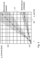
- a brake pressure p_bremse can be controlled according to the currently determined deceleration z_soll, which is then adjusted during braking according to the quotient F_hor/F_vert at the fifth wheel plate 15 in a tolerance band 17, as shown in Fig. 5 shown can be corrected.
- the solution described thus describes a method for controlling the braking system of a trailer vehicle 1, in which the horizontal force F_hor between the towing vehicle 9 and the trailer vehicle 1 is measured and a proportion of the mass of the trailer vehicle that is braked by the towing vehicle 9 is determined from this and the braking force on the trailer vehicle 1 is adjusted so that on the fifth wheel plate 15 of the towing vehicle 9, the quotient of F_hor and the support load F_vert corresponds to the current braking z_soll of the trailer vehicle 1.
Landscapes
- Engineering & Computer Science (AREA)
- Transportation (AREA)
- Mechanical Engineering (AREA)
- Physics & Mathematics (AREA)
- Fluid Mechanics (AREA)
- Regulating Braking Force (AREA)
Applications Claiming Priority (1)
| Application Number | Priority Date | Filing Date | Title |
|---|---|---|---|
| DE102023117135.6A DE102023117135A1 (de) | 2023-06-29 | 2023-06-29 | Verfahren zur autarken Steuerung einer Bremsanlage eines Anhängerfahrzeuges eines Sattelzuges |
Publications (2)
| Publication Number | Publication Date |
|---|---|
| EP4484231A1 true EP4484231A1 (fr) | 2025-01-01 |
| EP4484231B1 EP4484231B1 (fr) | 2026-03-25 |
Family
ID=93746060
Family Applications (1)
| Application Number | Title | Priority Date | Filing Date |
|---|---|---|---|
| EP24179016.1A Active EP4484231B1 (fr) | 2023-06-29 | 2024-05-30 | Procédé de commande autonome d'un système de freinage d'un véhicule tracté d'un semi-remorque |
Country Status (2)
| Country | Link |
|---|---|
| EP (1) | EP4484231B1 (fr) |
| DE (1) | DE102023117135A1 (fr) |
Citations (5)
| Publication number | Priority date | Publication date | Assignee | Title |
|---|---|---|---|---|
| DE4212161A1 (de) * | 1992-04-10 | 1993-10-14 | Klaus Maier | Sattelauflieger |
| DE4243245A1 (de) * | 1992-12-19 | 1994-06-23 | Wabco Westinghouse Fahrzeug | Verfahren zur Abbremsung eines Fahrzeugzuges |
| EP0575936B1 (fr) | 1992-06-26 | 1996-08-21 | KNORR-BREMSE SYSTEME FÜR NUTZFAHRZEUGE GmbH | Méthode et dispositif pour la commande électronique de la force d'accouplement de véhicules composés de plusieurs parties |
| DE19812719A1 (de) * | 1998-03-24 | 1999-09-30 | Siegfried Joachim | Zugabstimmungssteuerung zur Angleichung der Abbremsung von Zugfahrzeug und Anhänger |
| US20240068894A1 (en) * | 2022-08-25 | 2024-02-29 | Range Energy Inc. | System and method for dynamic tow of a trailer |
Family Cites Families (2)
| Publication number | Priority date | Publication date | Assignee | Title |
|---|---|---|---|---|
| US4804234A (en) * | 1987-04-27 | 1989-02-14 | Eaton Corporation | Tractor-trailer brake control system |
| DE4313198C3 (de) * | 1993-04-22 | 2002-02-07 | Knorr Bremse Systeme | Verfahren zum Ermitteln der beim Bremsvorgang von einem Anhänger auf ein Zugfahrzeug ausgeübten Auflaufkraft |
-
2023
- 2023-06-29 DE DE102023117135.6A patent/DE102023117135A1/de not_active Withdrawn
-
2024
- 2024-05-30 EP EP24179016.1A patent/EP4484231B1/fr active Active
Patent Citations (5)
| Publication number | Priority date | Publication date | Assignee | Title |
|---|---|---|---|---|
| DE4212161A1 (de) * | 1992-04-10 | 1993-10-14 | Klaus Maier | Sattelauflieger |
| EP0575936B1 (fr) | 1992-06-26 | 1996-08-21 | KNORR-BREMSE SYSTEME FÜR NUTZFAHRZEUGE GmbH | Méthode et dispositif pour la commande électronique de la force d'accouplement de véhicules composés de plusieurs parties |
| DE4243245A1 (de) * | 1992-12-19 | 1994-06-23 | Wabco Westinghouse Fahrzeug | Verfahren zur Abbremsung eines Fahrzeugzuges |
| DE19812719A1 (de) * | 1998-03-24 | 1999-09-30 | Siegfried Joachim | Zugabstimmungssteuerung zur Angleichung der Abbremsung von Zugfahrzeug und Anhänger |
| US20240068894A1 (en) * | 2022-08-25 | 2024-02-29 | Range Energy Inc. | System and method for dynamic tow of a trailer |
Also Published As
| Publication number | Publication date |
|---|---|
| DE102023117135A1 (de) | 2025-01-02 |
| EP4484231B1 (fr) | 2026-03-25 |
Similar Documents
| Publication | Publication Date | Title |
|---|---|---|
| EP2994355B1 (fr) | Procédé de freinage d'un ensemble véhicule tracteur-remorque avec une force de freinage de remorque réduite en fonction de la réaction du système abs du véhicule tracteur | |
| EP3362331B1 (fr) | Procédé pour empêcher préventivement le basculement d'un véhicule | |
| EP0697314B1 (fr) | Procédé de contrôle de la pression de freinage selon la charge d'un combinaison tracteur remorque | |
| EP1359076B1 (fr) | Procédé et dispositif de commande d'énergie d'actionnement de frein des systèmes de freinage à commande électronique pour combinaisons de au moins un tracteur et une remorque | |
| DE3501179A1 (de) | Elektrische bremsanlage | |
| EP3353025B1 (fr) | Procédé de réglage des pressions de freinage d'un véhicule automobile, système de freinage pour la mise en oeuvre de ce procédé et véhicule à moteur doté d'un tel système de freinage | |
| EP2987694B1 (fr) | Procede de commande de freins dans un vehicule automobile et vehicule automobile avec une unite de commande dans laquelle le procede est execute | |
| EP3962761B1 (fr) | Procédé de détermination d'une charge d'essieu sur un véhicule à suspension mécanique | |
| EP0575936B1 (fr) | Méthode et dispositif pour la commande électronique de la force d'accouplement de véhicules composés de plusieurs parties | |
| EP2168788A1 (fr) | Dispositif et procédé d'exécution d'un réglage de la position d'une roue pour véhicules utilitaires | |
| EP3466754A1 (fr) | Procédé et dispositif de réglage de la portée lumineuse d'un phare | |
| DE19648936A1 (de) | Verfahren und Vorrichtung zur Steuerung der Bremsanlage eines Fahrzeugs | |
| DE19633834B4 (de) | Verfahren und Vorrichtung zur Steuerung der Bremsanlage eines Fahrzeuges | |
| EP4484231B1 (fr) | Procédé de commande autonome d'un système de freinage d'un véhicule tracté d'un semi-remorque | |
| WO2024132400A1 (fr) | Procédé de détermination d'un écart de performance entre une performance cible et une performance réelle d'un actionneur de véhicule | |
| DE10197123B4 (de) | Verfahren und System für Bremsen von Nutzfahrzeugen | |
| EP3476627A1 (fr) | Véhicule tracteur et semi-remorque | |
| DE19858583A1 (de) | Verfahren und Vorrichtung zur Steuerung einer Bremsanlage eines Fahrzeugs | |
| EP2679458B1 (fr) | Dispositif et procédé de commande électronique d'un frein de service d'un véhicule | |
| DE102023107310A1 (de) | Verfahren und Bremssystem zur Ansteuerung einen Bremsaktuators zum Abbau von Verspannungen eines Fahrzeugs | |
| WO2024227650A1 (fr) | Procédé de fonctionnement d'un frein de service d'un véhicule, en particulier d'un véhicule utilitaire, programme informatique et/ou support lisible par ordinateur, dispositif de commande et véhicule, en particulier véhicule utilitaire | |
| DE102023136213A1 (de) | Verfahren zum Betreiben eines Antiblockiersystems eines Fahrzeugs, insbesondere Nutzfahrzeugs, Computerprogramm und/oder computerlesbares Medium, Steuergerät und Fahrzeug, insbesondere Nutzfahrzeug | |
| EP4419400A1 (fr) | Dispositif de commande et procédé pour augmenter la précision de mesure d'un système de mesure de charge d'essieu embarqué | |
| DE102023125299A1 (de) | Verfahren zum Betreiben eines elektropneumatischen Bremssystems für ein Fahrzeug, insbesondere Nutzfahrzeug, Computerprogramm und/oder computerlesbares Medium, Steuergerät, und Fahrzeug | |
| DE102018123098A1 (de) | Verfahren zur Bestimmung des Drucks in Tragbälgen eines Achsaggregats für ein mehrachsiges Fahrzeug |
Legal Events
| Date | Code | Title | Description |
|---|---|---|---|
| PUAI | Public reference made under article 153(3) epc to a published international application that has entered the european phase |
Free format text: ORIGINAL CODE: 0009012 |
|
| STAA | Information on the status of an ep patent application or granted ep patent |
Free format text: STATUS: THE APPLICATION HAS BEEN PUBLISHED |
|
| AK | Designated contracting states |
Kind code of ref document: A1 Designated state(s): AL AT BE BG CH CY CZ DE DK EE ES FI FR GB GR HR HU IE IS IT LI LT LU LV MC ME MK MT NL NO PL PT RO RS SE SI SK SM TR |
|
| STAA | Information on the status of an ep patent application or granted ep patent |
Free format text: STATUS: REQUEST FOR EXAMINATION WAS MADE |
|
| 17P | Request for examination filed |
Effective date: 20250605 |
|
| GRAP | Despatch of communication of intention to grant a patent |
Free format text: ORIGINAL CODE: EPIDOSNIGR1 |
|
| STAA | Information on the status of an ep patent application or granted ep patent |
Free format text: STATUS: GRANT OF PATENT IS INTENDED |
|
| GRAJ | Information related to disapproval of communication of intention to grant by the applicant or resumption of examination proceedings by the epo deleted |
Free format text: ORIGINAL CODE: EPIDOSDIGR1 |
|
| STAA | Information on the status of an ep patent application or granted ep patent |
Free format text: STATUS: REQUEST FOR EXAMINATION WAS MADE |
|
| INTG | Intention to grant announced |
Effective date: 20251204 |
|
| INTC | Intention to grant announced (deleted) | ||
| GRAP | Despatch of communication of intention to grant a patent |
Free format text: ORIGINAL CODE: EPIDOSNIGR1 |
|
| STAA | Information on the status of an ep patent application or granted ep patent |
Free format text: STATUS: GRANT OF PATENT IS INTENDED |
|
| GRAS | Grant fee paid |
Free format text: ORIGINAL CODE: EPIDOSNIGR3 |
|
| INTG | Intention to grant announced |
Effective date: 20260115 |
|
| GRAA | (expected) grant |
Free format text: ORIGINAL CODE: 0009210 |
|
| STAA | Information on the status of an ep patent application or granted ep patent |
Free format text: STATUS: THE PATENT HAS BEEN GRANTED |
|
| AK | Designated contracting states |
Kind code of ref document: B1 Designated state(s): AL AT BE BG CH CY CZ DE DK EE ES FI FR GB GR HR HU IE IS IT LI LT LU LV MC ME MK MT NL NO PL PT RO RS SE SI SK SM TR |
|
| REG | Reference to a national code |
Ref country code: CH Ref legal event code: F10 Free format text: ST27 STATUS EVENT CODE: U-0-0-F10-F00 (AS PROVIDED BY THE NATIONAL OFFICE) Effective date: 20260325 Ref country code: GB Ref legal event code: FG4D Free format text: NOT ENGLISH |
|
| REG | Reference to a national code |
Ref country code: DE Ref legal event code: R096 Ref document number: 502024000921 Country of ref document: DE |
|
| REG | Reference to a national code |
Ref country code: IE Ref legal event code: FG4D Free format text: LANGUAGE OF EP DOCUMENT: GERMAN |