EP4484309A2 - Dispositif de marquage de récipients et procédé de fonctionnement associé - Google Patents
Dispositif de marquage de récipients et procédé de fonctionnement associé Download PDFInfo
- Publication number
- EP4484309A2 EP4484309A2 EP24179717.4A EP24179717A EP4484309A2 EP 4484309 A2 EP4484309 A2 EP 4484309A2 EP 24179717 A EP24179717 A EP 24179717A EP 4484309 A2 EP4484309 A2 EP 4484309A2
- Authority
- EP
- European Patent Office
- Prior art keywords
- laser marking
- module
- laser
- container
- containers
- Prior art date
- Legal status (The legal status is an assumption and is not a legal conclusion. Google has not performed a legal analysis and makes no representation as to the accuracy of the status listed.)
- Pending
Links
Images
Classifications
-
- B—PERFORMING OPERATIONS; TRANSPORTING
- B41—PRINTING; LINING MACHINES; TYPEWRITERS; STAMPS
- B41M—PRINTING, DUPLICATING, MARKING, OR COPYING PROCESSES; COLOUR PRINTING
- B41M5/00—Duplicating or marking methods; Sheet materials for use therein
- B41M5/0082—Digital printing on bodies of particular shapes
-
- B—PERFORMING OPERATIONS; TRANSPORTING
- B65—CONVEYING; PACKING; STORING; HANDLING THIN OR FILAMENTARY MATERIAL
- B65C—LABELLING OR TAGGING MACHINES, APPARATUS, OR PROCESSES
- B65C3/00—Labelling other than flat surfaces
- B65C3/06—Affixing labels to short rigid containers
- B65C3/08—Affixing labels to short rigid containers to container bodies
-
- B—PERFORMING OPERATIONS; TRANSPORTING
- B23—MACHINE TOOLS; METAL-WORKING NOT OTHERWISE PROVIDED FOR
- B23K—SOLDERING OR UNSOLDERING; WELDING; CLADDING OR PLATING BY SOLDERING OR WELDING; CUTTING BY APPLYING HEAT LOCALLY, e.g. FLAME CUTTING; WORKING BY LASER BEAM
- B23K26/00—Working by laser beam, e.g. welding, cutting or boring
- B23K26/36—Removing material
- B23K26/362—Laser etching
-
- B—PERFORMING OPERATIONS; TRANSPORTING
- B41—PRINTING; LINING MACHINES; TYPEWRITERS; STAMPS
- B41J—TYPEWRITERS; SELECTIVE PRINTING MECHANISMS, i.e. MECHANISMS PRINTING OTHERWISE THAN FROM A FORME; CORRECTION OF TYPOGRAPHICAL ERRORS
- B41J2/00—Typewriters or selective printing mechanisms characterised by the printing or marking process for which they are designed
- B41J2/435—Typewriters or selective printing mechanisms characterised by the printing or marking process for which they are designed characterised by selective application of radiation to a printing material or impression-transfer material
- B41J2/44—Typewriters or selective printing mechanisms characterised by the printing or marking process for which they are designed characterised by selective application of radiation to a printing material or impression-transfer material using single radiation source per colour, e.g. lighting beams or shutter arrangements
- B41J2/442—Typewriters or selective printing mechanisms characterised by the printing or marking process for which they are designed characterised by selective application of radiation to a printing material or impression-transfer material using single radiation source per colour, e.g. lighting beams or shutter arrangements using lasers
-
- B—PERFORMING OPERATIONS; TRANSPORTING
- B41—PRINTING; LINING MACHINES; TYPEWRITERS; STAMPS
- B41J—TYPEWRITERS; SELECTIVE PRINTING MECHANISMS, i.e. MECHANISMS PRINTING OTHERWISE THAN FROM A FORME; CORRECTION OF TYPOGRAPHICAL ERRORS
- B41J2/00—Typewriters or selective printing mechanisms characterised by the printing or marking process for which they are designed
- B41J2/435—Typewriters or selective printing mechanisms characterised by the printing or marking process for which they are designed characterised by selective application of radiation to a printing material or impression-transfer material
- B41J2/447—Typewriters or selective printing mechanisms characterised by the printing or marking process for which they are designed characterised by selective application of radiation to a printing material or impression-transfer material using arrays of radiation sources
- B41J2/455—Typewriters or selective printing mechanisms characterised by the printing or marking process for which they are designed characterised by selective application of radiation to a printing material or impression-transfer material using arrays of radiation sources using laser arrays, the laser array being smaller than the medium to be recorded
-
- B—PERFORMING OPERATIONS; TRANSPORTING
- B41—PRINTING; LINING MACHINES; TYPEWRITERS; STAMPS
- B41J—TYPEWRITERS; SELECTIVE PRINTING MECHANISMS, i.e. MECHANISMS PRINTING OTHERWISE THAN FROM A FORME; CORRECTION OF TYPOGRAPHICAL ERRORS
- B41J29/00—Details of, or accessories for, typewriters or selective printing mechanisms not otherwise provided for
- B41J29/12—Guards, shields or dust excluders
- B41J29/13—Cases or covers
-
- B—PERFORMING OPERATIONS; TRANSPORTING
- B41—PRINTING; LINING MACHINES; TYPEWRITERS; STAMPS
- B41J—TYPEWRITERS; SELECTIVE PRINTING MECHANISMS, i.e. MECHANISMS PRINTING OTHERWISE THAN FROM A FORME; CORRECTION OF TYPOGRAPHICAL ERRORS
- B41J29/00—Details of, or accessories for, typewriters or selective printing mechanisms not otherwise provided for
- B41J29/17—Cleaning arrangements
-
- B—PERFORMING OPERATIONS; TRANSPORTING
- B41—PRINTING; LINING MACHINES; TYPEWRITERS; STAMPS
- B41J—TYPEWRITERS; SELECTIVE PRINTING MECHANISMS, i.e. MECHANISMS PRINTING OTHERWISE THAN FROM A FORME; CORRECTION OF TYPOGRAPHICAL ERRORS
- B41J29/00—Details of, or accessories for, typewriters or selective printing mechanisms not otherwise provided for
- B41J29/377—Cooling or ventilating arrangements
-
- B—PERFORMING OPERATIONS; TRANSPORTING
- B41—PRINTING; LINING MACHINES; TYPEWRITERS; STAMPS
- B41J—TYPEWRITERS; SELECTIVE PRINTING MECHANISMS, i.e. MECHANISMS PRINTING OTHERWISE THAN FROM A FORME; CORRECTION OF TYPOGRAPHICAL ERRORS
- B41J3/00—Typewriters or selective printing or marking mechanisms characterised by the purpose for which they are constructed
- B41J3/407—Typewriters or selective printing or marking mechanisms characterised by the purpose for which they are constructed for marking on special material
- B41J3/4073—Printing on three-dimensional objects not being in sheet or web form, e.g. spherical or cubic objects
- B41J3/40731—Holders for objects, e. g. holders specially adapted to the shape of the object to be printed or adapted to hold several objects
-
- B—PERFORMING OPERATIONS; TRANSPORTING
- B41—PRINTING; LINING MACHINES; TYPEWRITERS; STAMPS
- B41J—TYPEWRITERS; SELECTIVE PRINTING MECHANISMS, i.e. MECHANISMS PRINTING OTHERWISE THAN FROM A FORME; CORRECTION OF TYPOGRAPHICAL ERRORS
- B41J3/00—Typewriters or selective printing or marking mechanisms characterised by the purpose for which they are constructed
- B41J3/407—Typewriters or selective printing or marking mechanisms characterised by the purpose for which they are constructed for marking on special material
- B41J3/4073—Printing on three-dimensional objects not being in sheet or web form, e.g. spherical or cubic objects
- B41J3/40733—Printing on cylindrical or rotationally symmetrical objects, e. g. on bottles
-
- B—PERFORMING OPERATIONS; TRANSPORTING
- B41—PRINTING; LINING MACHINES; TYPEWRITERS; STAMPS
- B41M—PRINTING, DUPLICATING, MARKING, OR COPYING PROCESSES; COLOUR PRINTING
- B41M5/00—Duplicating or marking methods; Sheet materials for use therein
- B41M5/26—Thermography ; Marking by high energetic means, e.g. laser otherwise than by burning, and characterised by the material used
-
- B—PERFORMING OPERATIONS; TRANSPORTING
- B65—CONVEYING; PACKING; STORING; HANDLING THIN OR FILAMENTARY MATERIAL
- B65C—LABELLING OR TAGGING MACHINES, APPARATUS, OR PROCESSES
- B65C3/00—Labelling other than flat surfaces
- B65C3/06—Affixing labels to short rigid containers
- B65C3/08—Affixing labels to short rigid containers to container bodies
- B65C3/14—Affixing labels to short rigid containers to container bodies the container being positioned for labelling with its centre-line vertical
-
- B—PERFORMING OPERATIONS; TRANSPORTING
- B65—CONVEYING; PACKING; STORING; HANDLING THIN OR FILAMENTARY MATERIAL
- B65C—LABELLING OR TAGGING MACHINES, APPARATUS, OR PROCESSES
- B65C9/00—Details of labelling machines or apparatus
- B65C9/0062—Interchangeable modules, e.g. applicator heads with label magazines and glue rollers
-
- B—PERFORMING OPERATIONS; TRANSPORTING
- B65—CONVEYING; PACKING; STORING; HANDLING THIN OR FILAMENTARY MATERIAL
- B65C—LABELLING OR TAGGING MACHINES, APPARATUS, OR PROCESSES
- B65C9/00—Details of labelling machines or apparatus
- B65C9/02—Devices for moving articles, e.g. containers, past labelling station
- B65C9/04—Devices for moving articles, e.g. containers, past labelling station having means for rotating the articles
-
- B—PERFORMING OPERATIONS; TRANSPORTING
- B65—CONVEYING; PACKING; STORING; HANDLING THIN OR FILAMENTARY MATERIAL
- B65C—LABELLING OR TAGGING MACHINES, APPARATUS, OR PROCESSES
- B65C9/00—Details of labelling machines or apparatus
- B65C9/26—Devices for applying labels
-
- B—PERFORMING OPERATIONS; TRANSPORTING
- B65—CONVEYING; PACKING; STORING; HANDLING THIN OR FILAMENTARY MATERIAL
- B65C—LABELLING OR TAGGING MACHINES, APPARATUS, OR PROCESSES
- B65C9/00—Details of labelling machines or apparatus
- B65C9/40—Controls; Safety devices
Definitions
- the invention relates to a device for marking containers.
- the invention further relates to a method for operating a device for marking containers.
- containers are mostly equipped with labels.
- Typical variants are paper or plastic labels, which are processed with hot or cold glue or self-adhesive and applied to the containers. Labels can be problematic in the recycling process, e.g. because of the printing ink used, waterproof paper, glue, etc.
- Required information could, for example, be marked or written directly onto the containers using a laser marking system.
- a laser marking system Such technology is already used, for example, to laser mark a production number or a best-before date.
- the laser beam and the heat generated on the surface of the container can cause a physical change to the surface of the container (e.g. stress whitening in PET containers), so that the desired characters can be laser marked onto the surface.
- the invention is based on the object of creating a more flexible technology for marking containers for a container treatment plant.
- the device has a container conveyor, preferably a rotary container conveyor, for transporting the containers.
- the device also has a coupling unit and a labeling module that can be coupled to the coupling unit for applying labels to the containers transported by the container conveyor.
- the device also has a laser marking module that can be used for laser marking the container transported by the container conveyor can be coupled to the coupling unit.
- the labeling module and the laser marking module can be coupled to the coupling unit in an interchangeable manner.
- the device can be used particularly flexibly, as the labeling module and the laser marking module can be coupled to the same coupling unit, so that the device can be used flexibly and as required for labeling with the labeling module or for laser marking with the laser marking module.
- the modular design and the coupling unit mean that switching between the labeling module and the laser marking module can be carried out relatively quickly and easily. This can be used, for example, to equip a first product with labels from the labeling module, and after changing the modules, a second product can simply be marked with a laser mark from the laser marking module.
- This technology also makes it possible for devices already in operation with coupling unit(s) and labeling module(s) to be easily retrofitted for laser marking, as the laser marking module fits onto the existing coupling unit(s). This also makes it possible to achieve a relatively low-effort transition to completely label-free containers.
- a laser marking applied by the laser marking module can comprise a decoration, a decorative surface, at least one character and/or a single- or multi-line character string.
- the device further comprises (at least) one further coupling unit, which is arranged in front of or behind the coupling unit with respect to a container transport direction of the container conveyor.
- the device further comprises (at least) one further laser marking module, which can be coupled to the (at least one) further coupling unit for laser marking the containers transported by the container conveyor.
- the coupling unit and the (at least one) further coupling unit can be of identical construction.
- the laser marking module and the (at least one) further laser marking module can be of identical construction.
- At least one marking head of the laser marking module can have a relative position to the container conveyor when the laser marking module is coupled to the coupling unit. which differs from a relative position between at least one further marking head of the further laser marking module to the container conveyor when the further laser marking module is coupled to the further coupling unit.
- the device can have (at least) one further labeling module which can be coupled to the (at least one) further coupling unit for applying labels to the containers transported by the container conveyor.
- the (at least one) further labeling module and the (at least one) further laser marking module can be coupled to the (at least one) further coupling unit in an interchangeable manner.
- a labeling module and a laser marking module can be coupled to a respective coupling unit on the device.
- Combined decorations can advantageously be made possible by combining the labeling and laser marking modules in one device.
- the labeling module and/or the laser marking module have rollers for moving over a surface.
- the respective module can thus advantageously be moved in a simple manner towards the coupling unit and away from the coupling unit.
- the coupling unit is designed so that the labeling module is raised when coupled to the coupling unit and/or the laser marking module is raised when coupled to the coupling unit. This advantageously enables very precise positioning of the respective module and eliminates the influence of uneven ground, etc. on the positioning accuracy.
- the laser marking module has a movable module carriage and a laser marking system for laser marking, which is preferably arranged as an exchangeable sub-module on the module carriage (and e.g. secured, preferably with a quick-release fastener or a tool-free quick-change system).
- a laser marking system for laser marking which is preferably arranged as an exchangeable sub-module on the module carriage (and e.g. secured, preferably with a quick-release fastener or a tool-free quick-change system).
- the labeling module can have a movable module carriage that is identical in construction to the module carriage of the laser marking module. This advantageously allows the flexibility of the module concept to be further increased.
- the laser marking module has at least one marking head for laser marking the containers, wherein a position of the at least one marking head is adjustable (e.g. manually or by motor), preferably height-adjustable, transversely to a transport direction of the container conveyor and/or longitudinally to a transport direction of the container conveyor and/or radially to the container conveyor.
- the laser marking module can thus advantageously be adaptable, e.g. in order to be able to set a desired distance to the container to be laser marked, in order to be able to laser mark different areas of containers or in order to be able to adapt the laser marking module to different container formats.
- the laser marking module has several marking heads for laser marking different areas of the containers.
- the several marking heads can be arranged one above the other or side by side.
- the laser marking module has a suction device for sucking away vapors generated during laser marking. This advantageously allows additional functionality to be integrated into the laser marking module, whereby the integrated suction device can prevent the device and the containers from becoming contaminated by the vapors.
- the laser marking module has a cooling device (e.g. air cooling device, liquid cooling device or electric cooling device) which is connected to the (at least one) laser source in a heat-transfer manner for cooling (at least) one laser source of the laser marking module, preferably for cooling the laser source with cooling water.
- a cooling device e.g. air cooling device, liquid cooling device or electric cooling device
- this allows further functionality to be integrated into the laser marking module, with the integrated cooling device making it possible to use comparatively powerful laser sources and/or to extend the service life of the laser source.
- the laser marking module has a cleaning device for automatically cleaning a focusing device of the laser marking module.
- a cleaning device for automatically cleaning a focusing device of the laser marking module.
- the laser marking module has a preferably camera-based detection device for individually detecting a position and/or orientation of a marking area of the container in order to adapt the laser marking to the detected position and/or orientation.
- a further functionality can thus be integrated into the laser marking module, wherein the integrated detection device can improve the positioning accuracy of the laser marking in the respective marking area of the container.
- the laser marking module has a laser protection housing to shield the laser marking of the containers. This advantageously allows additional functionality to be integrated into the laser marking module, whereby the integrated laser protection housing can prevent operators from being injured by the laser beam in the event of improper use.
- the laser protection housing or at least a part thereof can be moved between an operating position and a maintenance position, preferably in a guided manner (e.g. manually or automatically), preferably raised and lowered. This can advantageously significantly improve ergonomics.
- the laser marking module has a locking device, preferably mechanical and/or electronic, for locking the laser protection housing or at least a part thereof in the operating position.
- the locking device can be designed to lock the laser protection housing or at least a part thereof in the operating position when the laser marking module is or will be coupled to the coupling unit.
- the locking device can be designed to release the laser protection housing or at least a part thereof for movement into the maintenance position when the laser marking module is or will be uncoupled from the coupling unit. This can advantageously achieve a particularly high level of security.
- the suction device, the cooling device, the cleaning device, the detection device, the laser protection housing and/or the locking device can be arranged as an exchangeable sub-module on the module carriage (and secured, for example, preferably with a quick-release fastener or a tool-free quick-change system).
- This can advantageously Flexibility can be further increased because different sub-modules can be quickly and easily arranged and secured on the module trolley for different tasks.
- control device can refer to electronics (e.g. designed as a driver circuit or with microprocessor(s) and data storage) and/or a mechanical, pneumatic and/or hydraulic control system, which, depending on its design, can take on control tasks and/or regulation tasks and/or processing tasks. Even if the term “control” is used here, it can also appropriately include or mean “regulation” or “control with feedback” and/or “processing”.
- control device can be a central control device of the device.
- control device can be arranged in a decentralized manner, e.g. partially on the laser marking module and/or the labeling module.
- the container conveyor is designed to rotate the containers about a vertical axis of the respective container (e.g. by means of rotatable container holders of the container conveyor).
- the at least one first operating parameter can have a first container rotation speed and/or a first container rotation profile for rotating the containers about the vertical axis of the respective container
- the at least one second operating parameter can have a second container rotation speed that differs from the first container rotation speed and/or a second container rotation profile that differs from the first container rotation profile. for rotating the containers around the vertical axis of the respective container. This allows the rotation of the containers and the type of marking (labeling and/or laser marking) to be automatically coordinated.
- the device further comprises an inspection device which is designed to detect the laser markings applied to the containers by the laser marking module and to adapt the operation of the device (e.g. the control device) depending on the detected laser markings.
- the applied laser markings can advantageously be monitored in this way.
- suction device, the cooling device, the detection device, the cleaning device, the laser protection housing, the locking device, the control device and/or the inspection device is part of the laser marking module or is included separately from the laser marking module as part of the device.
- a further aspect of the present disclosure relates to a container treatment system for producing, cleaning, coating, testing, filling, closing, marking and/or packaging containers for liquid media, preferably beverages or liquid foodstuffs, with a device for marking as disclosed herein or with a laser marking module as disclosed herein.
- the containers can be designed as bottles, cans, canisters, cartons, flacons, etc.
- Another aspect of the present disclosure relates to a laser marking module as disclosed herein.
- Another aspect of the present disclosure relates to a device for marking containers as disclosed herein, without a labeling module.
- a further aspect relates to a method for operating a device for labelling containers as disclosed herein.
- the method comprises operating the device in a first operating mode, in which the labelling module is coupled to the coupling unit, with at least one first operating parameter, preferably comprising a first conveying speed, a first container rotation speed and/or a first container rotation profile.
- the method comprises operating the device in a second operating mode, in which the laser marking module is coupled to the coupling unit, with at least one second operating parameter, preferably having a second conveying speed, a second container rotation speed and/or a second container rotation profile, which differs from the at least one first operating parameter.
- the method can achieve the same advantages that have already been described with reference to the device.
- the device in the second operating mode, the device cannot apply any labels to the containers.
- the containers can be marked by the device completely without labels, namely only by laser marking using the laser marking module.
- no labeling module may be coupled to the device.
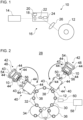
- the Figure 1 shows a laser marking system 10 for laser marking containers 12.
- the laser marking system 10 can also be referred to as a laser marking system, laser coding system or laser inscription system.
- the laser marking system 10 can be a COZ laser marking system, a fiber laser marking system or a UV laser marking system.
- the laser marking system 10 may comprise a laser source 14 and a marking head 16.
- the laser source 14 can be designed, for example, as a laser tube.
- the laser tube can be sealed.
- the laser tube can be filled with a gas, e.g. containing CO2, or a gas mixture, e.g. CO2-N2-He gas mixture.
- Electrodes can also be arranged in the laser tube.
- a supply unit can be connected to the electrodes (not shown in Figure 1 ).
- the supply unit can supply the laser source 14 with electrical energy.
- molecules, e.g. CO2 molecules in the laser tube can be excited to oscillate and thus emit a laser beam.
- the laser source 14 can also be referred to as an oscillator.
- the laser beam generated by the laser source 14 can be guided or directed to the marking head 16 directly or via mirrors. It is possible that, for example, a so-called telescope for expanding the laser beam is arranged between the laser source 14 and the marking head 16.
- the marking head 16 can preferably have two movable mirrors 18 and 22 and two drives 20 and 24.
- the marking head 16 can also have a focusing device 26.
- the marking head 16 can also be referred to as a coding head, identification head or writing head.
- the first drive 20 can rotate the first mirror 18 about a first axis (e.g. x-axis).
- the first mirror 18 can also be referred to as a movable scanner mirror, e.g. X-scanner mirror.
- the second drive 24 can rotate the second mirror 22 about a second axis (e.g. y-axis).
- the second mirror 22 can also be referred to as a movable scanner mirror, e.g. Y-scanner mirror.
- the first axis and the second axis can preferably run perpendicular to one another.
- the mirrors 18, 22 moved by the drives 20, 24 can direct the laser beam according to the desired laser marking.
- the laser beam can thus, for example, write over the surface of the container 12.
- the laser beam can move over the surface of the container 12 within a marking field that is assigned to the respective marking head 16.
- the focusing device 26 can have a focusing lens for this purpose, for example.
- the focusing lens can also be referred to as a condenser lens.
- the focusing lens can be an F-Theta lens, for example.
- the focusing lens can be arranged inside or outside the marking head 16.
- the focusing device 26 can also have a protective screen for protecting the focusing lens, for example.
- the laser marking system 10 can have a plurality of marking heads 16.
- the plurality of marking heads 16 can, for example, be arranged side by side and/or one above the other. For example, two, three or more marking heads 16 can be included.
- Each marking head 16 can be connected to its own laser source 14, which can emit a laser beam to the respective marking head 16. Accordingly, the laser marking system 10 can have multiple laser sources 14.
- a beam distributor can be arranged between the laser source 14 and several marking heads 16.
- the beam distributor can, for example, split a laser beam received from the laser source 14 into several laser beams and guide them to the several marking heads 16.
- laser sources 14 can be of identical construction, for example. However, it is also possible for the laser sources 14 to be at least partially designed differently in order to be able to produce different effects (e.g. color effects, haptic effects, surface structures) when laser marking the containers 12.
- effects e.g. color effects, haptic effects, surface structures
- the Figure 2 shows purely schematically and by way of example a device 28 for marking containers 12.
- the device 28 has a container conveyor 30, at least one coupling unit 38, at least one labeling module 40 and at least one laser marking module 42.
- the device 28 can also have a control device 58.
- the container conveyor 30 is designed to transport containers 12.
- the container conveyor 30 can transport the containers 12 in one transport direction.
- the container conveyor 30 can be a rotary container conveyor (container conveyor carousel).
- the container conveyor 30 can be, for example, a linear container conveyor (not in Figure 2 shown).
- the container conveyor 30 can support the containers 12 during transport, preferably on the bottom side, the circumference side and/or the mouth side.
- the container conveyor 30 can have container holders 32 for supporting the containers 12.
- the container holders 32 can hold the containers 12 preferably in base handling or neck handling.
- the container conveyor 30 does not have any separate container holders 32 and, for example, the containers 12 are simply supported on a preferably rotating conveyor element (e.g. belt, strap, chains or plates) of the container conveyor 30 (not in Figure 2 shown).
- a preferably rotating conveyor element e.g. belt, strap, chains or plates
- the container holders 32 can each support a container 12.
- the container holders 32 can each have, for example, a container plate (e.g. container turntable), a centering bell, a container clamp and/or an inflation device.
- a container 12 can be fixed between a container plate and a centering bell.
- An optional, additional inflation device can provide additional stability, e.g. when the containers 12 are marked before filling.
- the container conveyor 30 can be designed to rotate the transported containers 12 each about its own vertical axis.
- the container holders 32 can be rotatable for rotating the containers 12 about their respective vertical axis.
- An infeed conveyor 34 can feed the containers 12 to the container conveyor 30.
- the infeed conveyor 34 can be designed as a transfer star, for example. It is possible that the infeed conveyor 34 is designed for a pitch delay or for changing a pitch delay.
- An outlet conveyor 36 can transport the containers 12 away from the container conveyor 30 after marking.
- the outlet conveyor 36 can be designed as a transfer star, for example.
- the at least one coupling unit 38 is designed for coupling to the modules 40, 42, which in turn are designed for coupling to the at least one coupling unit 38.
- a special feature of the present disclosure may be that the labeling module(s) 40 and the laser marking module(s) 42 can be coupled to the same coupling unit(s) 38.
- the labeling module(s) 40 and the laser marking module(s) 42 can thus be coupled to the coupling unit(s) 38 in an interchangeable manner.
- the device 28 has a plurality of coupling units 38, e.g. between two and six coupling units 38.
- coupling units 38 e.g. between two and six coupling units 38.
- the coupling units 38 In order to improve readability, reference is made below primarily to the plural form with regard to the coupling units 38. It is understood that the explanations can equally apply to embodiments in which only one coupling unit 38 is included.
- the coupling units 38 are preferably of identical construction. However, it is also possible that the coupling units 38 are at least partially designed differently.
- the coupling units 38 can be arranged one after the other and at a distance from one another with respect to a transport direction of the container conveyor 30.
- the coupling units 38 can be arranged on an outer side, e.g. outer peripheral side, of the container conveyor 30.
- the coupling units 38 can be designed so that the respective coupling module 40, 42 is raised when it is coupled to the respective coupling unit 38.
- the coupling units 38 can each have a lifting device.
- the lifting devices can, for example, have a motor drive.
- the coupling module 40, 42 can be raised by means of a lifting device.
- the lifting device can raise the respective module 40, 42 into an operating position when coupling, in which the respective module 40, 42 preferably no longer has direct contact with the ground.
- the lifting device can lower the respective module 40, 42 into a starting position when uncoupling, in which the respective module 40, 42 preferably has direct contact with the ground and can be moved away.
- the coupling units 38 can be designed for mechanically coupling and uncoupling a respective module 40, 42.
- the coupling units 38 can each have a centering cone (or a centering cone) that fits together with a centering cone (or a centering cone) of the respective module 40, 42 for positioning the respective module 40, 42.
- the modules 40, 42 can be moved, preferably driven, over a surface.
- the modules 40, 42 can each have a movable module carriage 43 for moving over the ground.
- the module carriages 43 can preferably be designed as mobile underframes.
- the module carriages 43 of the modules 40, 42 can preferably be of identical construction.
- the module carriage 43 of the labeling module 40 can carry a replaceable labeling unit for labeling the containers 12.
- the module carriage 43 of the laser marking module 42 can carry the replaceable laser marking system 10.
- the modules 40, 42 or the module carriages 43 can each have several rollers 44 for moving over the ground.
- the rollers 44 are in the operating position of the respective module 40, 42 without contact with the ground.
- the device 28 preferably has a plurality of labeling modules 40.
- labeling modules 40 In order to improve readability, reference is made below primarily to the plural form with regard to the labeling modules 40. It is understood that the explanations can equally apply to embodiments in which only one labeling module 40 is included.
- the labeling modules 40 are designed to apply labels to the containers 12.
- the labeling modules 40 can apply labels to the containers 12 when they are coupled to the coupling units 38.
- the labeling modules 40 can, for example, apply paper or plastic labels to the containers 12.
- the labels can, for example, be applied to the containers 12 using hot glue or cold glue or with self-adhesive tape.
- the device 28 preferably has a plurality of laser marking modules 42.
- the device 28 preferably has a plurality of laser marking modules 42.
- the laser marking modules 42 are designed to laser mark the containers 12.
- the laser marking modules 42 can apply laser markings to the containers 12 when they are coupled to the coupling units 38.
- the laser marking modules 42 each have a laser marking system 10 with one or more marking heads 16 (see Figure 1 ).
- a position of at least one marking head 16 of the laser marking system 10 can be adjustable.
- the adjustment device for adjusting the position of the at least one marking head 16 can be manually operated or motor-driven, for example.
- the adjustment device preferably has a guide with which the at least one marking head 16 can be guided during adjustment.
- the at least one marking head 16 can be height-adjustable.
- the at least one marking head 16 can be adjustable, for example, transversely to a transport direction of the container conveyor 30 and/or longitudinally to a transport direction of the container conveyor 30.
- the laser marking modules 42 are of identical construction.
- the laser marking modules 42 are set up so that they can mark different sections of the containers 12, e.g. several sections arranged one above the other.
- a marking head 16 (see Figure 1) of a laser marking module 42 can be positioned in a higher position than a marking head 16 (see Figure 1 ) of another laser marking module 42.
- the previously explained adjustability or adjustment device can be used, for example.
- the laser marking modules 42 can particularly preferably have further devices with which operation of the respective laser marking module 42 can be improved.
- the laser marking modules 42 can each have a suction device 46, a cooling device 48, a detection device 50, a cleaning device 52, a laser protection housing 54 and/or a locking device 56.
- the laser marking system 10, the suction device 46, the cooling device 48, the detection device 50, the cleaning device 52, the laser protection housing 54 and/or the locking device 56 can each be designed as an exchangeable sub-module for arrangement on the module carriage 43 as required, e.g. by means of a preferably tool-free quick-change system.
- the module carriage 43 can have at least one sub-module holder for receiving at least one sub-module.
- the suction device 46 can be designed to extract vapors generated during laser marking.
- the suction device 46 can be directed at a marking field of the laser marking system 10 when the respective laser marking module 42 is coupled to the coupling unit 38.
- the suction device 46 is arranged above the at least one marking head 16 (see Figure 1 ) and/or the container conveyor 30 when the respective laser marking module 42 is coupled to the coupling unit 38.
- the suction device 46 can preferably be arranged within the laser protection housing 54.
- the suction device 46 can be accessible in a maintenance position of the laser protection housing 54.
- the extraction device 46 can, for example, have a fan and a pipe system.
- the fan can convey extracted vapors from the laser marking through the pipe system.
- the pipe system can, for example, include a filter.
- the pipe system can open into the environment or a reservoir, e.g. a tank.
- the cooling device 48 can be connected to the laser source 14 in a heat-transfer manner to cool the laser source 14 of the laser marking system 10.
- the cooling device 48 can be, for example, an air cooling device, a liquid cooling device or an electric cooling device.
- the cooling device 48 can preferably carry a cooling liquid, e.g. cooling water, in a cooling circuit.
- a first heat exchanger can connect the laser source 14 to the cooling circuit in a heat-transfer manner to cool the laser source 14.
- a second heat exchanger can connect the cooling circuit to an environment in a heat-transfer manner. The second heat exchanger can preferably be supplied with ambient air by a fan.
- the cooling device 48 can be arranged at least partially outside the laser protection housing 54, e.g. to facilitate maintenance.
- the second heat exchanger and optionally also the first heat exchanger can be arranged outside the laser protection housing 54.
- the detection device 50 can be designed for the individual detection of a position and/or orientation of a respective marking area of the containers 12.
- the detection device 50 can, for example, have at least one camera.
- the detection device 50 can be directed at the container conveyor when the laser marking module 42 is coupled to the coupling unit 38.
- a control device 58 can adapt an operation of the laser marking system 10, preferably on an individual container basis.
- the detection device 50 can be arranged outside the laser protection housing 54.
- the cleaning device 52 can be designed to automatically clean the focusing device 26 of the laser marking system 10.
- the cleaning device 52 can, for example, automatically clean a focusing lens and/or a protective screen of the focusing device 26.
- the cleaning device 52 can clean the focusing device 26 at regular intervals and/or after triggering by means of a user input device.
- the cleaning device 52 can spray the focusing device 26 with a cleaning fluid, e.g. air or cleaning liquid, for example by means of a nozzle.
- a cleaning fluid e.g. air or cleaning liquid
- the nozzle can be connected to the environment via a compressor or to a cleaning liquid tank via a pump.
- the cleaning device 52 can clean the focusing device 26, e.g. by wiping it, for example with a fabric or a (e.g. windshield) wiper.
- the cleaning device 52 can be arranged within the laser protection housing 54.
- the cleaning device 52 can be accessible in a maintenance position of the laser protection housing 54.
- the laser protection housing 54 can be designed to shield the laser marking of the containers 12.
- the laser protection housing 54 can have housing walls and/or tinted windows to shield the laser marking.
- the laser protection housing 54 is preferably movable between an operating position and a maintenance position. The movement can be effected manually or automatically. The movement of the laser protection housing 54 can be guided by a (e.g. vertical) guide. The laser protection housing 54 can preferably be raised from the operating position to the maintenance position and lowered from the maintenance position to the operating position.
- the laser source 14, the marking head 16 and/or the focusing device 26 can be arranged in a protected manner in the operating position in the laser protection housing 54. In the maintenance position, the laser source 14, the marking head 16 and/or the focusing device 26 can be accessible.
- the optional locking device 56 can be designed to lock the laser protection housing 54 in the operating position.
- the locking device 56 can be, for example, a mechanical and/or electronic locking device.
- the locking device 56 can electronically monitor with a corresponding sensor or similar whether the laser marking module 42 is coupled to the coupling unit 38 or not. It is also possible for the locking device 56 to have, for example, a mechanical switch that is actuated when coupling to the coupling unit 38 or when uncoupling from the coupling unit 38.
- the locking device 56 can lock the laser protection housing 54 in the operating position when the laser marking module 42 is or will be coupled to the coupling unit 38 and/or release the laser protection housing 54 for movement into the maintenance position when the laser marking module 42 is or will be uncoupled from the coupling unit 38.
- the locking of the laser protection housing 54 in the operating position by means of the locking device 56 can be done electronically and/or mechanically, for example.
- the locking device 56 can interrupt an electrical supply line to a drive for moving the laser protection housing 54. It is also possible for a movable latch or similar of the locking device 56 to block the laser protection housing 54 in the operating position.
- the container conveyor 30 and/or a machine frame of the device 28 may be equipped with a protective device for shielding the laser marking, e.g. in at least one gap between adjacent coupling units 38.
- the control device 58 may be configured to operate the device 28 in a first operating mode when at least one labeling module 40 is coupled to the coupling unit(s) 38 and in a second operating mode when at least one laser marking module 42 is coupled to the coupling unit(s) 38.
- the device 28 can be operated with different operating parameters than in the second operating mode.
- a container conveying speed, a container rotation speed (with respect to rotation about a vertical axis of the respective container 12) and/or a container rotation profile can each have a different value than in the second operating mode.
- the container rotation profile can, for example, indicate whether the containers 12 are rotated about their own vertical axis at all, when the containers 12 are rotated about their own vertical axis, how long the containers 12 are rotated about their own vertical axis, at what speed the containers 12 are rotated about their own vertical axis and/or by what Angle of rotation the containers 12 can be rotated around their own vertical axis, e.g. by the container holders 32.
- the device 28 can also have an inspection device 60, preferably a camera-based one.
- the inspection device 60 can detect the laser markings applied to the containers 12 by the laser marking module 42 and, for example, check or evaluate them with regard to quality, etc.
- an operation of the device 28 can be adapted (e.g. via the control device 58). For example, a container transport speed of the container conveyor 30 or a container rotation speed of the container conveyor 30 can be reduced if it is recognized that the applied laser markings are incomplete, or a warning can be issued to a user via an output device.
- the invention is not limited to the preferred embodiments described above. Rather, a large number of variants and modifications are possible which also make use of the inventive concept and therefore fall within the scope of protection.
- the invention also claims protection for the subject matter and the features of the subclaims independently of the claims referred to.
- the individual features of independent claim 1 are each disclosed independently of one another.
- the features of the subclaims are also disclosed independently of all features of independent claim 1 and, for example, independently of the features relating to the presence and/or configuration of the container conveyor, the coupling unit, the labeling module and/or the laser marking module of independent claim 1. All range specifications herein are to be understood as disclosed in such a way that all values falling within the respective range are disclosed individually, e.g. also as preferred, narrower outer limits of the respective range.
Landscapes
- Physics & Mathematics (AREA)
- Optics & Photonics (AREA)
- Engineering & Computer Science (AREA)
- Manufacturing & Machinery (AREA)
- Health & Medical Sciences (AREA)
- General Health & Medical Sciences (AREA)
- Toxicology (AREA)
- Plasma & Fusion (AREA)
- Mechanical Engineering (AREA)
- Laser Beam Processing (AREA)
- Labeling Devices (AREA)
Applications Claiming Priority (1)
| Application Number | Priority Date | Filing Date | Title |
|---|---|---|---|
| DE102023114693.9A DE102023114693A1 (de) | 2023-06-05 | 2023-06-05 | Vorrichtung zum Kennzeichnen von Behältern und zugehöriges Betriebsverfahren |
Publications (2)
| Publication Number | Publication Date |
|---|---|
| EP4484309A2 true EP4484309A2 (fr) | 2025-01-01 |
| EP4484309A3 EP4484309A3 (fr) | 2025-04-16 |
Family
ID=91375718
Family Applications (1)
| Application Number | Title | Priority Date | Filing Date |
|---|---|---|---|
| EP24179717.4A Pending EP4484309A3 (fr) | 2023-06-05 | 2024-06-03 | Dispositif de marquage de récipients et procédé de fonctionnement associé |
Country Status (4)
| Country | Link |
|---|---|
| US (1) | US20240399775A1 (fr) |
| EP (1) | EP4484309A3 (fr) |
| CN (1) | CN119079255A (fr) |
| DE (1) | DE102023114693A1 (fr) |
Family Cites Families (7)
| Publication number | Priority date | Publication date | Assignee | Title |
|---|---|---|---|---|
| EP1493671B1 (fr) * | 2003-07-02 | 2006-10-25 | Khs Ag | Support mobile pour module |
| DE102009035880B4 (de) * | 2009-08-03 | 2012-02-02 | Khs Gmbh | Behandlungsmaschine zum Behandeln von Packmitteln und Verfahren zum ausgerichteten Andocken eines Behandlungsmoduls an eine Behandlungsmaschine |
| DE102010033171A1 (de) * | 2010-08-03 | 2012-02-09 | Krones Aktiengesellschaft | Verfahren und Vorrichtung zum Betreiben einer Anlage zum Behandeln von Behältnissen mit übergeordneter Parameteranwahl |
| ITTO20120211U1 (it) * | 2012-12-18 | 2014-06-19 | Sidel Spa Con Socio Unico | Macchina per il trattamento di contenitori, in particolare contenitori o bottiglie in plastica, e contenitori utilizzati in tale macchina |
| DE102013212125A1 (de) * | 2013-06-25 | 2015-01-08 | Krones Aktiengesellschaft | Maschinenschutzeinrichtung |
| ITUB20156259A1 (it) * | 2015-12-04 | 2017-06-04 | Pe Labellers Spa | Gruppo di etichettatura per macchine etichettatrici. |
| US12415643B2 (en) * | 2021-09-14 | 2025-09-16 | P.E. Labellers S.P.A. | Labeling assembly for labeling machines |
-
2023
- 2023-06-05 DE DE102023114693.9A patent/DE102023114693A1/de active Pending
-
2024
- 2024-06-03 EP EP24179717.4A patent/EP4484309A3/fr active Pending
- 2024-06-04 CN CN202410715256.4A patent/CN119079255A/zh active Pending
- 2024-06-05 US US18/734,435 patent/US20240399775A1/en active Pending
Also Published As
| Publication number | Publication date |
|---|---|
| CN119079255A (zh) | 2024-12-06 |
| DE102023114693A1 (de) | 2024-12-05 |
| EP4484309A3 (fr) | 2025-04-16 |
| US20240399775A1 (en) | 2024-12-05 |
Similar Documents
| Publication | Publication Date | Title |
|---|---|---|
| EP2029442B1 (fr) | Procédé et dispositif pour l'impression de récipients | |
| EP2762317B1 (fr) | Dispositifs d'impression de récipients et procédé associé | |
| EP3337667B1 (fr) | Machine d'impression directe et procédé pour effectuer une impression directe sur des contenants | |
| EP2140966B1 (fr) | Dispositif et méthode pour l'inscription de récipients utilisant plusieurs sources laser diode directes | |
| EP2199220B1 (fr) | Machine d'équipement d'articles et procédé de commande de la machine | |
| EP2832546B1 (fr) | Imprimante dotée d'une commande de tête d'impression | |
| DE102009058212B4 (de) | Verfahren zum Betreiben einer Anlage zum Bedrucken von Behältern | |
| EP3377325B1 (fr) | Machine d'impression directe et procédé pour effectuer une impression directe sur des contenants | |
| DE102008051791A1 (de) | Verfahren sowie Vorrichtung zum Ausstatten von Behältern | |
| DE69205500T2 (de) | Entwässerungsvorrichtung für Behälter, die markiert werden sollen. | |
| EP1449778A1 (fr) | Modules pour machines d'étiquetage | |
| DE102013208065A1 (de) | Rundläufermaschine zur Bedruckung von Behältern | |
| EP4188714B1 (fr) | Dispositif de gaufrage ou d'étiquetage de récipients | |
| EP3450183B1 (fr) | Machine et procédé d'impression directe destinés à l'impression de récipients par impression directe | |
| EP4484309A2 (fr) | Dispositif de marquage de récipients et procédé de fonctionnement associé | |
| EP1762384A2 (fr) | Procédé et dispositif pour marquer dans une machine de traitement de matériau en feuilles | |
| DE102023114692A1 (de) | Vorrichtung und Verfahren zum Kennzeichnen von Behältern | |
| DE102024128858A1 (de) | Verfahren und Vorrichtung zum Lasermarkieren von Objekten mit einer gekrümmten Fläche | |
| EP4335647A1 (fr) | Machine d'impression directe | |
| DE202008018588U1 (de) | Streckblasmaschine mit Druckeinheit | |
| WO2017207577A1 (fr) | Dispositif et procédé pour nettoyer un cylindre de contre-pression central d'une machine d'impression flexographique |
Legal Events
| Date | Code | Title | Description |
|---|---|---|---|
| PUAI | Public reference made under article 153(3) epc to a published international application that has entered the european phase |
Free format text: ORIGINAL CODE: 0009012 |
|
| STAA | Information on the status of an ep patent application or granted ep patent |
Free format text: STATUS: THE APPLICATION HAS BEEN PUBLISHED |
|
| AK | Designated contracting states |
Kind code of ref document: A2 Designated state(s): AL AT BE BG CH CY CZ DE DK EE ES FI FR GB GR HR HU IE IS IT LI LT LU LV MC ME MK MT NL NO PL PT RO RS SE SI SK SM TR |
|
| PUAL | Search report despatched |
Free format text: ORIGINAL CODE: 0009013 |
|
| AK | Designated contracting states |
Kind code of ref document: A3 Designated state(s): AL AT BE BG CH CY CZ DE DK EE ES FI FR GB GR HR HU IE IS IT LI LT LU LV MC ME MK MT NL NO PL PT RO RS SE SI SK SM TR |
|
| RIC1 | Information provided on ipc code assigned before grant |
Ipc: B65C 9/40 20060101ALI20250312BHEP Ipc: B41J 3/407 20060101ALI20250312BHEP Ipc: B65C 9/00 20060101ALI20250312BHEP Ipc: B65C 3/14 20060101AFI20250312BHEP |
|
| STAA | Information on the status of an ep patent application or granted ep patent |
Free format text: STATUS: REQUEST FOR EXAMINATION WAS MADE |
|
| 17P | Request for examination filed |
Effective date: 20251016 |