EP4484325A1 - Vollkunststoffeinzelmaterial-presspumpe - Google Patents
Vollkunststoffeinzelmaterial-presspumpe Download PDFInfo
- Publication number
- EP4484325A1 EP4484325A1 EP22948920.8A EP22948920A EP4484325A1 EP 4484325 A1 EP4484325 A1 EP 4484325A1 EP 22948920 A EP22948920 A EP 22948920A EP 4484325 A1 EP4484325 A1 EP 4484325A1
- Authority
- EP
- European Patent Office
- Prior art keywords
- pump
- limiting stand
- plastic
- pump chamber
- rod
- Prior art date
- Legal status (The legal status is an assumption and is not a legal conclusion. Google has not performed a legal analysis and makes no representation as to the accuracy of the status listed.)
- Pending
Links
Images




Classifications
-
- B—PERFORMING OPERATIONS; TRANSPORTING
- B05—SPRAYING OR ATOMISING IN GENERAL; APPLYING FLUENT MATERIALS TO SURFACES, IN GENERAL
- B05B—SPRAYING APPARATUS; ATOMISING APPARATUS; NOZZLES
- B05B11/00—Single-unit hand-held apparatus in which flow of contents is produced by the muscular force of the operator at the moment of use
- B05B11/01—Single-unit hand-held apparatus in which flow of contents is produced by the muscular force of the operator at the moment of use characterised by the means producing the flow
- B05B11/10—Pump arrangements for transferring the contents from the container to a pump chamber by a sucking effect and forcing the contents out through the dispensing nozzle
- B05B11/1042—Components or details
-
- B—PERFORMING OPERATIONS; TRANSPORTING
- B05—SPRAYING OR ATOMISING IN GENERAL; APPLYING FLUENT MATERIALS TO SURFACES, IN GENERAL
- B05B—SPRAYING APPARATUS; ATOMISING APPARATUS; NOZZLES
- B05B11/00—Single-unit hand-held apparatus in which flow of contents is produced by the muscular force of the operator at the moment of use
- B05B11/01—Single-unit hand-held apparatus in which flow of contents is produced by the muscular force of the operator at the moment of use characterised by the means producing the flow
- B05B11/10—Pump arrangements for transferring the contents from the container to a pump chamber by a sucking effect and forcing the contents out through the dispensing nozzle
- B05B11/1042—Components or details
- B05B11/1073—Springs
- B05B11/1074—Springs located outside pump chambers
-
- B—PERFORMING OPERATIONS; TRANSPORTING
- B05—SPRAYING OR ATOMISING IN GENERAL; APPLYING FLUENT MATERIALS TO SURFACES, IN GENERAL
- B05B—SPRAYING APPARATUS; ATOMISING APPARATUS; NOZZLES
- B05B11/00—Single-unit hand-held apparatus in which flow of contents is produced by the muscular force of the operator at the moment of use
- B05B11/01—Single-unit hand-held apparatus in which flow of contents is produced by the muscular force of the operator at the moment of use characterised by the means producing the flow
- B05B11/10—Pump arrangements for transferring the contents from the container to a pump chamber by a sucking effect and forcing the contents out through the dispensing nozzle
- B05B11/1001—Piston pumps
- B05B11/1023—Piston pumps having an outlet valve opened by deformation or displacement of the piston relative to its actuating stem
-
- B—PERFORMING OPERATIONS; TRANSPORTING
- B05—SPRAYING OR ATOMISING IN GENERAL; APPLYING FLUENT MATERIALS TO SURFACES, IN GENERAL
- B05B—SPRAYING APPARATUS; ATOMISING APPARATUS; NOZZLES
- B05B11/00—Single-unit hand-held apparatus in which flow of contents is produced by the muscular force of the operator at the moment of use
- B05B11/01—Single-unit hand-held apparatus in which flow of contents is produced by the muscular force of the operator at the moment of use characterised by the means producing the flow
- B05B11/10—Pump arrangements for transferring the contents from the container to a pump chamber by a sucking effect and forcing the contents out through the dispensing nozzle
-
- B—PERFORMING OPERATIONS; TRANSPORTING
- B05—SPRAYING OR ATOMISING IN GENERAL; APPLYING FLUENT MATERIALS TO SURFACES, IN GENERAL
- B05B—SPRAYING APPARATUS; ATOMISING APPARATUS; NOZZLES
- B05B11/00—Single-unit hand-held apparatus in which flow of contents is produced by the muscular force of the operator at the moment of use
- B05B11/01—Single-unit hand-held apparatus in which flow of contents is produced by the muscular force of the operator at the moment of use characterised by the means producing the flow
- B05B11/10—Pump arrangements for transferring the contents from the container to a pump chamber by a sucking effect and forcing the contents out through the dispensing nozzle
- B05B11/1001—Piston pumps
-
- B—PERFORMING OPERATIONS; TRANSPORTING
- B05—SPRAYING OR ATOMISING IN GENERAL; APPLYING FLUENT MATERIALS TO SURFACES, IN GENERAL
- B05B—SPRAYING APPARATUS; ATOMISING APPARATUS; NOZZLES
- B05B11/00—Single-unit hand-held apparatus in which flow of contents is produced by the muscular force of the operator at the moment of use
- B05B11/01—Single-unit hand-held apparatus in which flow of contents is produced by the muscular force of the operator at the moment of use characterised by the means producing the flow
- B05B11/10—Pump arrangements for transferring the contents from the container to a pump chamber by a sucking effect and forcing the contents out through the dispensing nozzle
- B05B11/1042—Components or details
- B05B11/1059—Means for locking a pump or its actuation means in a fixed position
-
- B—PERFORMING OPERATIONS; TRANSPORTING
- B05—SPRAYING OR ATOMISING IN GENERAL; APPLYING FLUENT MATERIALS TO SURFACES, IN GENERAL
- B05B—SPRAYING APPARATUS; ATOMISING APPARATUS; NOZZLES
- B05B11/00—Single-unit hand-held apparatus in which flow of contents is produced by the muscular force of the operator at the moment of use
- B05B11/01—Single-unit hand-held apparatus in which flow of contents is produced by the muscular force of the operator at the moment of use characterised by the means producing the flow
- B05B11/10—Pump arrangements for transferring the contents from the container to a pump chamber by a sucking effect and forcing the contents out through the dispensing nozzle
- B05B11/1042—Components or details
- B05B11/1073—Springs
- B05B11/1076—Traction springs, e.g. stretchable sleeve
-
- B—PERFORMING OPERATIONS; TRANSPORTING
- B05—SPRAYING OR ATOMISING IN GENERAL; APPLYING FLUENT MATERIALS TO SURFACES, IN GENERAL
- B05B—SPRAYING APPARATUS; ATOMISING APPARATUS; NOZZLES
- B05B11/00—Single-unit hand-held apparatus in which flow of contents is produced by the muscular force of the operator at the moment of use
- B05B11/01—Single-unit hand-held apparatus in which flow of contents is produced by the muscular force of the operator at the moment of use characterised by the means producing the flow
- B05B11/10—Pump arrangements for transferring the contents from the container to a pump chamber by a sucking effect and forcing the contents out through the dispensing nozzle
- B05B11/1042—Components or details
- B05B11/1073—Springs
- B05B11/1077—Springs characterised by a particular shape or material
-
- B—PERFORMING OPERATIONS; TRANSPORTING
- B05—SPRAYING OR ATOMISING IN GENERAL; APPLYING FLUENT MATERIALS TO SURFACES, IN GENERAL
- B05B—SPRAYING APPARATUS; ATOMISING APPARATUS; NOZZLES
- B05B11/00—Single-unit hand-held apparatus in which flow of contents is produced by the muscular force of the operator at the moment of use
- B05B11/01—Single-unit hand-held apparatus in which flow of contents is produced by the muscular force of the operator at the moment of use characterised by the means producing the flow
- B05B11/10—Pump arrangements for transferring the contents from the container to a pump chamber by a sucking effect and forcing the contents out through the dispensing nozzle
- B05B11/1042—Components or details
- B05B11/1043—Sealing or attachment arrangements between pump and container
- B05B11/1046—Sealing or attachment arrangements between pump and container the pump chamber being arranged substantially coaxially to the neck of the container
- B05B11/1047—Sealing or attachment arrangements between pump and container the pump chamber being arranged substantially coaxially to the neck of the container the pump being preassembled as an independent unit before being mounted on the container
-
- B—PERFORMING OPERATIONS; TRANSPORTING
- B05—SPRAYING OR ATOMISING IN GENERAL; APPLYING FLUENT MATERIALS TO SURFACES, IN GENERAL
- B05B—SPRAYING APPARATUS; ATOMISING APPARATUS; NOZZLES
- B05B11/00—Single-unit hand-held apparatus in which flow of contents is produced by the muscular force of the operator at the moment of use
- B05B11/01—Single-unit hand-held apparatus in which flow of contents is produced by the muscular force of the operator at the moment of use characterised by the means producing the flow
- B05B11/10—Pump arrangements for transferring the contents from the container to a pump chamber by a sucking effect and forcing the contents out through the dispensing nozzle
- B05B11/1042—Components or details
- B05B11/1066—Pump inlet valves
- B05B11/1067—Pump inlet valves actuated by pressure
-
- Y—GENERAL TAGGING OF NEW TECHNOLOGICAL DEVELOPMENTS; GENERAL TAGGING OF CROSS-SECTIONAL TECHNOLOGIES SPANNING OVER SEVERAL SECTIONS OF THE IPC; TECHNICAL SUBJECTS COVERED BY FORMER USPC CROSS-REFERENCE ART COLLECTIONS [XRACs] AND DIGESTS
- Y02—TECHNOLOGIES OR APPLICATIONS FOR MITIGATION OR ADAPTATION AGAINST CLIMATE CHANGE
- Y02W—CLIMATE CHANGE MITIGATION TECHNOLOGIES RELATED TO WASTEWATER TREATMENT OR WASTE MANAGEMENT
- Y02W30/00—Technologies for solid waste management
- Y02W30/50—Reuse, recycling or recovery technologies
- Y02W30/62—Plastics recycling; Rubber recycling
Definitions
- the present disclosure relates to the technical field related to press pumps, and particularly, to an all-plastic single-material press pump.
- Press pumps have been widely used in daily chemical products, bringing convenience to life.
- metal springs are generally used as the rebound devices of the press heads, and glass beads are used as one-way sealing elements. Therefore, existing press pumps typically include materials such as plastic, metal, and glass. This necessitates disassembly and sorting of the press pumps for recycling, which not only complicates the recycling process but also increases labor costs.
- All-plastic press pumps use all-plastic parts to solve the problem of disassembly and sorting.
- various parts of existing all-plastic press pumps usually use various types of plastics such as PP, PE, TPE, etc.
- plastics such as PP, PE, TPE, etc.
- different types of plastic materials have different melting points and crystallization properties, leading to poor compatibility.
- the contents of different types of plastic materials in the recycled materials are uncertain. If the recycled materials are directly blended and recycled without being sorted, the mechanical properties and aesthetic properties of the recycled mixed materials are degraded significantly.
- sorting methods the sorting process is time-consuming and costly, and the recycled materials are often mixed during recycling, resulting in recycled plastic products with inferior performance.
- the present disclosure is proposed based on this situation.
- one of the objectives of the present disclosure is to provide an all-plastic single-material press pump made of a single plastic material that does not require disassembling or sorting, thus facilitating recycling and reducing recycling costs.
- An all-plastic single-material press pump includes a press head, a pump housing, a lock bottle cap, a locking cap, a pump rod, a spring, a one-way valve, a piston, and a dip tube which are made of the same plastic material.
- the lock bottle cap is connected to an upper end of the pump housing in an inserted mode;
- the pump housing is provided with an upper pump chamber and a lower pump chamber;
- the locking cap is disposed between the upper pump chamber and the lower pump chamber;
- an upper end of the pump rod is fixedly inserted into the press head;
- the pump rod passes through the locking cap and extends into the lower pump chamber;
- the spring is disposed in the upper pump chamber;
- the pump rod is provided with a suction channel;
- a lower end of the pump rod is provided with a liquid inlet connecting the suction channel and the lower pump chamber;
- the piston is located in the lower pump chamber and is arranged around the pump rod to move up and down along with the pump rod;
- the one-way valve is located at a lower end of the lower pump chamber; and
- the dip tube is connected to a lower end of the pump housing in an inserted mode.
- the press head, the pump housing, the lock bottle cap, the locking cap, the pump rod, the spring, the one-way valve, the piston, and the dip tube are all made of a PE material or a PP material.
- a gasket is disposed inside the lock bottle cap, and the gasket is made of the same plastic material as the lock bottle cap.
- a locking structure restricting an upward and downward movement of the lock bottle cap is disposed on an outer wall of the pump housing.
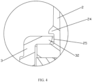
- the locking structure includes a clamping groove formed in the pump housing, a locking convex ring, and a clamping ring disposed on the lock bottle cap, and an upper side of the locking convex ring is provided with a conical surface gradually expanding from top to bottom, and an inner side surface of the clamping ring close to the pump housing is a conical surface gradually expanding from top to bottom.
- the pump rod is provided with an upper limiting stand and a lower limiting stand above and below the liquid inlet respectively
- the piston is located between the upper limiting stand and the lower limiting stand and is movable between the upper limiting stand and the lower limiting stand up and down
- the piston is provided with a sealing ring capable of cooperating with the lower limiting stand to achieve a sealed connection.
- the sealing ring capable of cooperating with the lower limiting stand to achieve a sealed connection.
- the lower limiting stand When the pump rod moves downwards, the lower limiting stand is separated from the sealing ring downwards, and the suction channel is communicated with the lower pump chamber through the liquid inlet, and the upper limiting stand moving downwards for a section can press the piston to push the piston to move downwards.
- an inner sleeve cooperating with the pump rod is disposed on the piston, the sealing ring is disposed at a lower end of the inner sleeve, the inner sleeve cooperates with the upper limiting stand through an upper end surface of the inner sleeve and is in sealed connection when the upper limiting stand presses downwards the upper end surface of the inner sleeve, and an upper end of the inner sleeve is provided with a convex ring protruding inwards and interfering and cooperating with an outer side wall of the pump rod.
- the spring is integrally formed by injection molding.
- the spring is of a hollow structure that is open at both ends, including an upper cup body, a lower cup body, and a straight cylinder body connecting the upper cup body and the lower cup body, all of which are elastic.
- the upper cup body and the lower cup body are symmetrically shaped into a cup shape.
- the inner diameters of the upper cup body and the lower cup body gradually expand from one end close to the straight cylinder body to the other end, and an outer protrusion is disposed at one end of each of the upper cup body and the lower cup body away from the straight cylinder body.
- the spring is of a hollow structure that is open at both ends, including an upper bowl body and a lower bowl body, both of which are elastic.
- the upper bowl body and the lower bowl body are symmetrical up and down, and the upper bowl body is shaped into a bowl-shaped structure with a large upper end and a small lower end.
- the lower bowl body is shaped into a bowl-shaped structure with a small upper end and a large lower end. The lower end of the upper bowl body and the upper end of the lower bowl body are connected to each other.
- the spring is an elastic plastic ring-shaped member with an opening in a side surface, and a reinforcing rib is disposed on an outer side surface of the elastic plastic ring-shaped member.
- a buckle capable of preventing the press head from being pressed downwards is detachably connected to the pump rod between the lock bottle cap and the press head.
- the buckle is made of the same plastic as the lock bottle cap.
- the present disclosure has the following beneficial effects. Since all parts of the present disclosure are made of a single type of plastic material, there is no need to disassemble and separate the press pump after recycling, and there is no need to sort different plastic materials.
- the plastic material can be directly melted into a liquid plastic and re-injected to form into other products for use, thereby lowering the difficulty and the recycling cost.
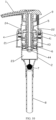
- an all-plastic single-material press pump which includes a press head 1, a pump housing 2, a lock bottle cap 3, a locking cap 21, a pump rod 4, a spring 5, a one-way valve 7, a piston 6, a dip tube 8 which are made of the same plastic material.
- the lock bottle cap 3 is connected to an upper end of the pump housing 2 in an inserted mode, the pump housing 2 is provided with an upper pump chamber 22 and a lower pump chamber 23.
- the locking cap 21 is disposed between the upper pump chamber 22 and the lower pump chamber 23.
- An upper end of the pump rod 4 is fixedly inserted into the press head 1.
- the pump rod 4 passes through the locking cap 21 and extends into the lower pump chamber 23.
- the spring 5 is disposed in the upper pump chamber 22.
- the pump rod 4 is provided with a suction channel 41.
- a lower end of the pump rod 4 is provided with a liquid inlet 42 connecting the suction channel 41 and the lower pump chamber 23.
- the piston 6 is located in the lower pump chamber 23 and is arranged around the pump rod 4 to move up and down along with the pump rod 4.
- the one-way valve 7 is located at a lower end of the lower pump chamber 23.
- the dip tube 8 is connected to a lower end of the pump housing 2 in an inserted mode.
- All parts of the all-plastic single-material press pump are made of the same type of plastic material. There is no need to disassemble and separate the press pump after recycling, and there is no need to sort different plastic materials.
- the plastic material can be directly melted into a liquid plastic and re-injected to form into other products for use, thereby lowering the difficulty and the recycling cost. Moreover, this also avoids the corrosion and contamination issues associated with the use of a metal spring.
- the press head 1, the pump housing 2, the lock bottle cap 3, the locking cap 21, the pump rod 4, the spring 5, the one-way valve 7, the piston 6, and the dip tube 8 are all made of a PE (Polyethylene) material or a PP (Polypropylene) material, such that the press pump is environmentally-friendly and safe.
- a gasket 31 is disposed on an inner side of the lock bottle cap 3.
- the gasket 31 is made of the same plastic material as the lock bottle cap 3.
- the gasket 31 can make the lock bottle cap 3 achieve better sealing when being connected to a daily chemical product bottle body.
- a locking structure restricting an upward and downward movement of the lock bottle cap 3 is disposed on an outer wall of the pump housing 2, which can prevent the pump housing 2 and the lock bottle cap 3 from loosening, thereby strengthening the stability of the connection.
- the locking structure includes a clamping groove 25 formed in the pump housing 2, a clamping convex ring 24, and a clamping ring 32 disposed on the lock bottle cap 3.
- An upper side of the locking convex ring 24 is provided with a conical surface gradually expanding from top to bottom, and an inner side surface of the clamping ring 32 close to the pump housing 2 is a conical surface gradually expanding from top to bottom.
- the locking convex ring 24 can limit the up-down movement of the lock bottle cap 3, so that the structure is simple and convenient and reliable.
- the clamping ring 32 is inserted into the clamping groove 25 from top to bottom, when the inner side surface of the clamping ring 32 close to the pump housing 2 is in contact with the conical surface on the upper side of the locking convex ring 24, the clamping ring 32 can be pressed into the clamping groove 25 downwards smoothly, so that there will be no major jamming when the clamping ring 32 is inserted into the clamping convex ring 24, making the assembling work of the lock bottle cap 3 and the pump housing 2 more convenient and smoother.
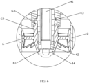
- the pump rod 4 is provided with an upper limiting stand 43 and a lower limiting stand 44 above and below the liquid inlet 42 respectively, and the piston 6 is located between the upper limiting stand 43 and the lower limiting stand 44 and can move up and down between the upper limiting stand 43 and the lower limiting stand 44.
- the piston 6 is provided with a sealing ring 61 capable of cooperating with the lower limiting stand 44 to achieve a sealed connection.
- a negative pressure is formed inside the lower pump chamber 23, and the one-way valve 7 is opened, allowing the liquid in the bottle to flow into the lower pump chamber 23 through the dip tube 8.
- the motion structure composed of the pump rod 4 and the piston 6 is simple, which facilitates easy assembly with fewer components.
- an inner sleeve 62 cooperating with the pump rod 4 is disposed on the piston 6.
- the sealing ring 61 is disposed at a lower end of the inner sleeve 62.
- the inner sleeve 62 cooperates with the upper limiting stand 43 through an upper end surface and is in sealed connection when the upper limiting stand 43 presses downwards the upper end surface of the inner sleeve 62, and an upper end of the inner sleeve 62 is provided with a convex ring protruding inwards and interfering and cooperating with an outer side wall of the pump rod 4.
- a lower middle part of the pump rod 4 is of a stepped shaft structure with a large top and a small bottom, and the outer diameter of the pump rod 4 corresponding to the upper limiting stand 43 is larger than the outer diameter of the pump rod 4 corresponding to the lower limiting stand 44.
- An inner hole of the inner sleeve 62 is large at the top and small at the bottom, and can allow the lower limiting stand 44 to pass from top to bottom and limit the passage of the upper limiting stand 43.
- the sealing ring 61 protrudes from a lower opening of the inner sleeve 62 and can allow the lower limiting stand 44 to pass from top to bottom under the action of an external force, resulting in a simple structure and easy assembly.
- the spring 5 is integrally formed by injection molding, which facilitates production and has high molding accuracy.
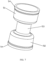
- the spring 5 is of a hollow structure that is open at both ends, including an upper cup body 51, a lower cup body 52, and a straight cylinder body 53 connecting the upper and lower cup bodies 52.
- the upper cup body 51 and the lower cup body 52 are symmetrical up and down and formed into a cup shape.
- the inner diameters of the upper cup body 51 and the lower cup body 52 both gradually expand from one end close to the straight cylinder body 53 to the other end.
- An outer protrusion 54 is disposed at one end of each of the upper cup body 51 and the lower cup body 52 away from the straight cylinder body 53.
- the spring is simple in structure and good in elasticity.
- the spring 5 is of a hollow structure that is open at both ends, including an upper bowl body 55 and a lower bowl body 56, both of which are elastic.
- the upper bowl body 55 and the lower bowl body 56 are symmetrical up and down, and the upper bowl body 55 is shaped into a bowl-shaped structure with a large upper end and a small lower end.
- the lower bowl body 56 is shaped into a bowl-shaped structure with a small upper end and a large lower end.
- the lower end of the upper bowl body 55 and the upper end of the lower bowl body 56 are connected to each other.
- the spring is simple in structure and good in elasticity.
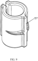
- the spring 5 is an elastic plastic ring-shaped member with an opening in a side surface.
- the spring is simple in structure and good in elasticity.
- a reinforcing rib 57 is disposed on an outer side surface of the elastic plastic ring-shaped member, which can enhance the strength of the elastic plastic ring-shaped member.
- a buckle 9 capable of preventing the press head 1 from being pressed downward is detachably connected to the pump rod 4 between the lock bottle cap 3 and the press head 1.
- the buckle 9 is made of the same type of plastic material as the lock bottle cap 3, which can prevent the user from accidentally pressing the press head 1 to cause liquid leakage.
- the one-way valve 7 is a pump bead.
- the pump bead is made of the same plastic material as the lock bottle cap 3 and has a simple structure.
Landscapes
- Reciprocating Pumps (AREA)
- Closures For Containers (AREA)
- Details Of Reciprocating Pumps (AREA)
- Containers And Packaging Bodies Having A Special Means To Remove Contents (AREA)
Applications Claiming Priority (2)
| Application Number | Priority Date | Filing Date | Title |
|---|---|---|---|
| CN202210732989.XA CN114873072A (zh) | 2022-06-27 | 2022-06-27 | 一种全塑单一材料按压泵 |
| PCT/CN2022/119647 WO2024000831A1 (zh) | 2022-06-27 | 2022-09-19 | 一种全塑单一材料按压泵 |
Publications (2)
| Publication Number | Publication Date |
|---|---|
| EP4484325A1 true EP4484325A1 (de) | 2025-01-01 |
| EP4484325A4 EP4484325A4 (de) | 2025-07-09 |
Family
ID=82681106
Family Applications (1)
| Application Number | Title | Priority Date | Filing Date |
|---|---|---|---|
| EP22948920.8A Pending EP4484325A4 (de) | 2022-06-27 | 2022-09-19 | Vollkunststoffeinzelmaterial-presspumpe |
Country Status (6)
| Country | Link |
|---|---|
| US (1) | US20250099995A1 (de) |
| EP (1) | EP4484325A4 (de) |
| JP (1) | JP7799073B2 (de) |
| CN (1) | CN114873072A (de) |
| CA (1) | CA3243259A1 (de) |
| WO (1) | WO2024000831A1 (de) |
Families Citing this family (4)
| Publication number | Priority date | Publication date | Assignee | Title |
|---|---|---|---|---|
| CN217696346U (zh) * | 2022-05-09 | 2022-11-01 | 中山市美捷时包装制品有限公司 | 一种全塑泡沫泵结构 |
| CN114873072A (zh) * | 2022-06-27 | 2022-08-09 | 中山市美捷时包装制品有限公司 | 一种全塑单一材料按压泵 |
| CN115069439A (zh) * | 2022-07-13 | 2022-09-20 | 广州尚功塑胶有限公司 | 一种单一材料的全塑泵及其应用的储料瓶 |
| CN118237193A (zh) * | 2024-05-09 | 2024-06-25 | 广东美捷时控股股份有限公司 | 一种全塑可回收按压泵 |
Family Cites Families (17)
| Publication number | Priority date | Publication date | Assignee | Title |
|---|---|---|---|---|
| JP3587940B2 (ja) * | 1996-08-15 | 2004-11-10 | 株式会社吉野工業所 | 液体吐出器 |
| JP4458894B2 (ja) | 2004-02-28 | 2010-04-28 | 株式会社吉野工業所 | 液体注出ポンプ装置 |
| ITVI20040183A1 (it) * | 2004-07-26 | 2004-10-26 | Taplast Spa | Elemento elastico per dispositivi erogatori di fluidi e relativo dispositivo di erogazione |
| CN107472683B (zh) | 2017-08-18 | 2023-04-11 | 潘玉霞 | 一种具有回吸功能的乳液泵 |
| US11035429B2 (en) | 2018-01-03 | 2021-06-15 | Silgan Dispensing Systems Corporation | Compression spring assembly and methods of using the same |
| CN210344127U (zh) * | 2019-07-29 | 2020-04-17 | 浙江晟祺实业有限公司 | 一种热塑性塑料弹簧及应用有该弹簧的泵芯结构 |
| CN110723408A (zh) * | 2019-10-18 | 2020-01-24 | 中山市美捷时包装制品有限公司 | 一种新型全塑料乳液泵结构 |
| KR102186042B1 (ko) | 2020-04-29 | 2020-12-03 | (주)연우 | 탄성 부재 및 이를 포함하는 펌프 조립체 |
| CN111924316A (zh) * | 2020-08-03 | 2020-11-13 | 宁波圣捷喷雾泵有限公司 | 一种环保液体泵 |
| KR102427023B1 (ko) * | 2020-08-24 | 2022-07-29 | 주식회사 삼화 | 액체 분사를 위한 펌프 |
| CN112173411A (zh) * | 2020-10-15 | 2021-01-05 | 中山市美捷时包装制品有限公司 | 一种全塑自锁泵 |
| CN214357714U (zh) * | 2020-12-23 | 2021-10-08 | 中山市美捷时包装制品有限公司 | 一种外置弹簧卡扣式按压泵 |
| CN112660600A (zh) * | 2020-12-23 | 2021-04-16 | 中山市美捷时包装制品有限公司 | 一种外置弹簧卡扣式按压泵结构 |
| CN214932184U (zh) * | 2021-05-19 | 2021-11-30 | 余姚市丹丹喷雾器有限公司 | 一种全塑可回收按压乳液泵 |
| CN114394327A (zh) * | 2022-01-18 | 2022-04-26 | 中山市美捷时包装制品有限公司 | 一种可回收全塑自锁泵 |
| CN114655563A (zh) * | 2022-03-30 | 2022-06-24 | 广州尚功塑胶有限公司 | 一种单一材料全塑乳液泵 |
| CN114873072A (zh) * | 2022-06-27 | 2022-08-09 | 中山市美捷时包装制品有限公司 | 一种全塑单一材料按压泵 |
-
2022
- 2022-06-27 CN CN202210732989.XA patent/CN114873072A/zh not_active Withdrawn
- 2022-09-19 WO PCT/CN2022/119647 patent/WO2024000831A1/zh not_active Ceased
- 2022-09-19 JP JP2024544657A patent/JP7799073B2/ja active Active
- 2022-09-19 EP EP22948920.8A patent/EP4484325A4/de active Pending
- 2022-09-19 CA CA3243259A patent/CA3243259A1/en active Pending
- 2022-09-19 US US18/832,505 patent/US20250099995A1/en active Pending
Also Published As
| Publication number | Publication date |
|---|---|
| CN114873072A (zh) | 2022-08-09 |
| EP4484325A4 (de) | 2025-07-09 |
| WO2024000831A1 (zh) | 2024-01-04 |
| US20250099995A1 (en) | 2025-03-27 |
| JP2025502530A (ja) | 2025-01-24 |
| CA3243259A1 (en) | 2025-02-25 |
| JP7799073B2 (ja) | 2026-01-14 |
Similar Documents
| Publication | Publication Date | Title |
|---|---|---|
| EP4484325A1 (de) | Vollkunststoffeinzelmaterial-presspumpe | |
| EP4428054A1 (de) | Recycelbare selbstsperrende vollkunststoffpumpe | |
| US11415120B2 (en) | Waterproof emulsion pump with external spring | |
| CN102991839B (zh) | 使用弹性体活塞的液体泵、活塞组件及其生产方法 | |
| US12138645B2 (en) | Liquid pump | |
| CN216200039U (zh) | 一种塑料弹簧 | |
| CN113800113A (zh) | 一种全塑料乳液泵头 | |
| CN112810992A (zh) | 一种全塑按压泵 | |
| CN113636206A (zh) | 一种全塑料乳液泵头 | |
| CN112896781A (zh) | 一种乳液泵 | |
| CN214398005U (zh) | 一种全塑按压泵 | |
| US20240299964A1 (en) | Full-plastic vacuum pump head and vessel with the pump head | |
| CN214609073U (zh) | 一种乳液泵 | |
| US12241464B2 (en) | Full-plastic liquid pump | |
| CN114348467B (zh) | 按压式双混合微型泵头 | |
| CN216862430U (zh) | 按压式双液微型泵头 | |
| CN217674320U (zh) | 一种全塑材料按压泵 | |
| CN216862336U (zh) | 一种可回收全塑自锁泵 | |
| CN118237192A (zh) | 泵组件及具有内容物排出功能的容器 | |
| CN112797097B (zh) | 一种弹簧及乳液泵 | |
| KR102283159B1 (ko) | Pp플라스틱 소재로만 이루어진 누름펌프 | |
| CN215157242U (zh) | 一种新型全塑乳液泵 | |
| CN115258400A (zh) | 一种活塞组件、喷雾泵及容器 | |
| CN113401493B (zh) | 泡沫泵 | |
| CN222630025U (zh) | 一种分离式瓶盖防漏密封结构 |
Legal Events
| Date | Code | Title | Description |
|---|---|---|---|
| STAA | Information on the status of an ep patent application or granted ep patent |
Free format text: STATUS: THE INTERNATIONAL PUBLICATION HAS BEEN MADE |
|
| PUAI | Public reference made under article 153(3) epc to a published international application that has entered the european phase |
Free format text: ORIGINAL CODE: 0009012 |
|
| STAA | Information on the status of an ep patent application or granted ep patent |
Free format text: STATUS: REQUEST FOR EXAMINATION WAS MADE |
|
| 17P | Request for examination filed |
Effective date: 20240927 |
|
| AK | Designated contracting states |
Kind code of ref document: A1 Designated state(s): AL AT BE BG CH CY CZ DE DK EE ES FI FR GB GR HR HU IE IS IT LI LT LU LV MC MK MT NL NO PL PT RO RS SE SI SK SM TR |
|
| REG | Reference to a national code |
Ref country code: DE Ref legal event code: R079 Free format text: PREVIOUS MAIN CLASS: B65D0047340000 Ipc: B05B0011100000 |
|
| A4 | Supplementary search report drawn up and despatched |
Effective date: 20250605 |
|
| RIC1 | Information provided on ipc code assigned before grant |
Ipc: B05B 11/10 20230101AFI20250530BHEP |
|
| DAV | Request for validation of the european patent (deleted) | ||
| DAX | Request for extension of the european patent (deleted) |