EP4484345A1 - Vorrichtung und verfahren zum wechseln eines bogenstapels in einem bogenzuführer - Google Patents
Vorrichtung und verfahren zum wechseln eines bogenstapels in einem bogenzuführer Download PDFInfo
- Publication number
- EP4484345A1 EP4484345A1 EP23181786.7A EP23181786A EP4484345A1 EP 4484345 A1 EP4484345 A1 EP 4484345A1 EP 23181786 A EP23181786 A EP 23181786A EP 4484345 A1 EP4484345 A1 EP 4484345A1
- Authority
- EP
- European Patent Office
- Prior art keywords
- stack
- sheets
- bars
- residual
- stabilizing
- Prior art date
- Legal status (The legal status is an assumption and is not a legal conclusion. Google has not performed a legal analysis and makes no representation as to the accuracy of the status listed.)
- Withdrawn
Links
- 238000000034 method Methods 0.000 title claims description 12
- 230000000087 stabilizing effect Effects 0.000 claims abstract description 95
- 239000011111 cardboard Substances 0.000 claims description 5
- 239000011087 paperboard Substances 0.000 claims description 4
- 230000003028 elevating effect Effects 0.000 claims description 2
- 239000002184 metal Substances 0.000 description 4
- 229910052751 metal Inorganic materials 0.000 description 4
- 239000012528 membrane Substances 0.000 description 3
- 239000000463 material Substances 0.000 description 2
- 239000004033 plastic Substances 0.000 description 2
- 229920003023 plastic Polymers 0.000 description 2
- 229910000831 Steel Inorganic materials 0.000 description 1
- 229910052782 aluminium Inorganic materials 0.000 description 1
- XAGFODPZIPBFFR-UHFFFAOYSA-N aluminium Chemical compound [Al] XAGFODPZIPBFFR-UHFFFAOYSA-N 0.000 description 1
- 239000002131 composite material Substances 0.000 description 1
- 239000010985 leather Substances 0.000 description 1
- 238000004519 manufacturing process Methods 0.000 description 1
- 239000000123 paper Substances 0.000 description 1
- 239000010959 steel Substances 0.000 description 1
- 230000001360 synchronised effect Effects 0.000 description 1
Images


Classifications
-
- B—PERFORMING OPERATIONS; TRANSPORTING
- B65—CONVEYING; PACKING; STORING; HANDLING THIN OR FILAMENTARY MATERIAL
- B65H—HANDLING THIN OR FILAMENTARY MATERIAL, e.g. SHEETS, WEBS, CABLES
- B65H1/00—Supports or magazines for piles from which articles are to be separated
- B65H1/26—Supports or magazines for piles from which articles are to be separated with auxiliary supports to facilitate introduction or renewal of the pile
- B65H1/263—Auxiliary supports for keeping the pile in the separation process during introduction of a new pile
-
- B—PERFORMING OPERATIONS; TRANSPORTING
- B65—CONVEYING; PACKING; STORING; HANDLING THIN OR FILAMENTARY MATERIAL
- B65H—HANDLING THIN OR FILAMENTARY MATERIAL, e.g. SHEETS, WEBS, CABLES
- B65H1/00—Supports or magazines for piles from which articles are to be separated
- B65H1/08—Supports or magazines for piles from which articles are to be separated with means for advancing the articles to present the articles to the separating device
- B65H1/14—Supports or magazines for piles from which articles are to be separated with means for advancing the articles to present the articles to the separating device comprising positively-acting mechanical devices
-
- B—PERFORMING OPERATIONS; TRANSPORTING
- B65—CONVEYING; PACKING; STORING; HANDLING THIN OR FILAMENTARY MATERIAL
- B65H—HANDLING THIN OR FILAMENTARY MATERIAL, e.g. SHEETS, WEBS, CABLES
- B65H2301/00—Handling processes for sheets or webs
- B65H2301/40—Type of handling process
- B65H2301/42—Piling, depiling, handling piles
- B65H2301/422—Handling piles, sets or stacks of articles
- B65H2301/4225—Handling piles, sets or stacks of articles in or on special supports
- B65H2301/42256—Pallets; Skids; Platforms with feet, i.e. handled together with the stack
-
- B—PERFORMING OPERATIONS; TRANSPORTING
- B65—CONVEYING; PACKING; STORING; HANDLING THIN OR FILAMENTARY MATERIAL
- B65H—HANDLING THIN OR FILAMENTARY MATERIAL, e.g. SHEETS, WEBS, CABLES
- B65H2404/00—Parts for transporting or guiding the handled material
- B65H2404/50—Surface of the elements in contact with the forwarded or guided material
- B65H2404/56—Flexible surface
- B65H2404/562—Flexible surface involving inflatable elements
-
- B—PERFORMING OPERATIONS; TRANSPORTING
- B65—CONVEYING; PACKING; STORING; HANDLING THIN OR FILAMENTARY MATERIAL
- B65H—HANDLING THIN OR FILAMENTARY MATERIAL, e.g. SHEETS, WEBS, CABLES
- B65H2405/00—Parts for holding the handled material
- B65H2405/30—Other features of supports for sheets
- B65H2405/32—Supports for sheets partially insertable - extractable, e.g. upon sliding movement, drawer
- B65H2405/323—Cantilever finger member, e.g. reciprocating in parallel to plane of handled material
- B65H2405/3231—Cantilever during insertion but supported on both sides of the pile upon full insertion
-
- B—PERFORMING OPERATIONS; TRANSPORTING
- B65—CONVEYING; PACKING; STORING; HANDLING THIN OR FILAMENTARY MATERIAL
- B65H—HANDLING THIN OR FILAMENTARY MATERIAL, e.g. SHEETS, WEBS, CABLES
- B65H2405/00—Parts for holding the handled material
- B65H2405/30—Other features of supports for sheets
- B65H2405/32—Supports for sheets partially insertable - extractable, e.g. upon sliding movement, drawer
- B65H2405/324—Supports for sheets partially insertable - extractable, e.g. upon sliding movement, drawer between operative position and non operative position
-
- B—PERFORMING OPERATIONS; TRANSPORTING
- B65—CONVEYING; PACKING; STORING; HANDLING THIN OR FILAMENTARY MATERIAL
- B65H—HANDLING THIN OR FILAMENTARY MATERIAL, e.g. SHEETS, WEBS, CABLES
- B65H2511/00—Dimensions; Position; Numbers; Identification; Occurrences
- B65H2511/10—Size; Dimensions
- B65H2511/13—Thickness
-
- B—PERFORMING OPERATIONS; TRANSPORTING
- B65—CONVEYING; PACKING; STORING; HANDLING THIN OR FILAMENTARY MATERIAL
- B65H—HANDLING THIN OR FILAMENTARY MATERIAL, e.g. SHEETS, WEBS, CABLES
- B65H2555/00—Actuating means
- B65H2555/10—Actuating means linear
- B65H2555/11—Actuating means linear pneumatic, e.g. inflatable elements
-
- B—PERFORMING OPERATIONS; TRANSPORTING
- B65—CONVEYING; PACKING; STORING; HANDLING THIN OR FILAMENTARY MATERIAL
- B65H—HANDLING THIN OR FILAMENTARY MATERIAL, e.g. SHEETS, WEBS, CABLES
- B65H2801/00—Application field
- B65H2801/03—Image reproduction devices
- B65H2801/21—Industrial-size printers, e.g. rotary printing press
Definitions
- the invention refers to a device for changing a stack of sheets in a sheet feeder for a sheet-converting machine that can be operated without interruptions.
- the machine comprises a main supporting unit with an actuating unit for lifting and lowering the main supporting unit.
- the main supporting unit has a supporting surface to support a pallet carrying a stack of sheets.
- the sheet feeder also has a residual stack supporting unit with an actuating unit for lifting and lowering the residual stack supporting unit. Having a residual stack in addition to another pile allows the feeder to work without interruptions.
- the residual stack supporting unit comprises a plurality of residual stack bars extending substantially parallel to each other, substantially parallel to the supporting surface and substantially horizontally. the residual stack bars are coupled to an actuating unit for deploying the residual stack bars into a sheets region and retracting the residual stack bars from said region.
- the residual stack bars are arranged in the related supporting unit in a rake-like manner such that they can be deployed in respective slots of the pallet. Said pallet sits on the main supporting unit when the residual stack bars are deployed in the sheet region.
- Sheet converting machines in the sense of the present patent application are for example sheet cutting machines, sheet creasing machines or sheet printing machines.
- sheet-converting machines can be adapted to any kind of sheet material. Examples thereof are paper, cardboard, plastics, metal, composite materials, and leather.
- the rake-like arrangement of the residual stack bars means that a plurality of residual stack bars extends in a substantially parallel manner from a common basis. Thereby, one end of each residual stack bar is connected to this common basis, wherein a respective opposite end freely protrudes therefrom.
- Other words designating this arrangement are "fork-like" or "grid”. In the present patent application, these terms are seen as synonyms.
- the invention is related to a method for changing a stack of sheets without having to stop the machine.
- the method follows the following steps:
- EP 0 958 215 B1 discloses a device as described above, which can be used to carry out a method as described above.
- EP 3 924 281 B1 discloses a method where the residual stack bars may be retracted individually, resulting in a complex system.
- WO2021122109 discloses a method where the residual stack bars are retracted using an oscillating motion, thereby generating vibrations in the whole converting machine.
- the invention adds, to a device for changing a stack of sheets described in the introductory part of this disclosure, a stabilizing unit with a stabilizing bar actuating unit adapted to deploy and retract at least one stabilizing bar into and from the feeder region, where stacks of sheets are operated.
- the stabilizing bar is deployed between the residual stack bars and are substantially parallel to the supporting surface.
- the stabilizing unit comprises a hindering actuating unit configured to change the thickness of the stabilizing bar from a sliding configuration to a hindering configuration and vice-versa. The thickness is measured along the lifting direction of the main supporting unit.
- the stabilizing unit prevents damage to the sheets when the residual stack bars are retracted. While the system may work with one stabilizing bar, it is preferred to use two to four stabilizing bars.
- the invention is also about a method for changing a stack of sheets in a sheet feeder for a sheet converting machine, comprising the following steps:
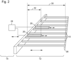
- Figure 1 shows a converting machine 1 with a sheet feeder 2.
- the sheet feeder 2 comprises a device 3 for changing a stack of sheets 4 in the sheet feeder 2.
- the device has a main supporting unit with a main stack actuating unit for lifting and lowering the main stack 4 by lifting or lowering the main supporting unit.
- the main supporting unit comprises a supporting surface 5 able to support a pallet 6 carrying a stack of sheets.
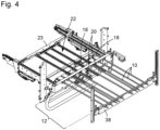
- the device also has a residual stack supporting unit 16 with a residual stack actuating unit for lifting and lowering a second stack of sheets by lifting and lowering the residual stack supporting unit 16.
- the second stack is a stack of sheets that has been partly consumed, where the supporting pallet 6 was removed to go fetch the next, replacement stack to be processed.
- the residual stack supporting unit 16 comprises a plurality of residual stack bars extending substantially parallel to each other and being substantially parallel to the supporting surface 5, i.e., being substantially horizontal.
- the residual stack bars 10 are coupled to a bar actuating unit 18 able to move the residual stack bars 10 into the feeder region 12 and retract the residual stack bars 10 from the feeder region 12, usually under the feed table 14 of the converting machine 1.
- the feeder region 12 is defined as the space in the feeder of the machine where the stacks of sheets are loaded and/or lifted.
- the residual stack bars 10 are arranged in the residual stack supporting unit 16 in a rake-like manner such that they can be positioned in respective slots 40 of a pallet 6 being supported on the main supporting unit when the residual stack bars 10 are in the feeder region 12.
- the device also has a stabilizing unit 22 with a stabilizing bar actuating unit 23 for deploying at least one, but preferably several stabilizing bars into the feeder region 12 and retracting them from the feeder region 12.
- the stabilizing bars 20 are moved into the feeder region 12 in-between the residual stack bars 10. They have the function of stabilizing the residual stack (i.e. the upper stack) and/or the replacement stack (i.e. the lower stack) to allow the residual stack supporting bars to retract without dragging the lowest sheet of the upper stack or the top sheet of the lower stack with them.
- the damages to the sheet occur when one of these sheets is dragged with the bars when the bar retracts. A damaged sheet may cause a machine jam and an interruption of the production process.
- the upper stack of sheets as the residual stack of sheets 8, the second stack of sheets or simply the stack of sheets.
- the lower stack of sheets as the replacement stack of sheets 4 or sometimes as the main stack of sheets.
- One way of moving the stabilizing bars 20 in between the residual stack bars 10 is by ensuring that the stabilizing bars 20 are thinner than the residual stack bars 10 and located in the same horizontal space/plane. Thus, said bars can be freely introduced between the residual stack of sheets 8 and the replacement stack of sheets 4 without touching the sheets.
- Another way of introducing the stabilizing bars 20 is to insert them into the feeder region 12 at a lower height than the residual stack bars 10 when there is enough space between the residual stack and the replacement stack of sheets 4, and then raising the stabilizing bars 20 to the height of the residual stack bars 10. By doing so, the stabilizing bars 20 do not need to be thinner than the residual stack bars 10 in the introductory step of the method.
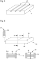
- the stabilizing unit 22 comprises a hindering actuating unit 24. It is configured to set the thickness of the stabilizing bars 20 from a sliding/thin configuration to a hindering/thick configuration and vice-versa. The thickness is measured along the lifting direction of the main supporting unit, in other words, we measure the thickness along a vertical direction.
- the bars have an inflatable part driven by a piston.
- the piston 58 can push compressed air in the inflatable part thereby increasing the thickness of the stabilizing bars 20.
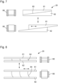
- the bars are made of two parts 61, 62 with an inclined surface 60 between them.
- the bar can be made thicker or thinner.
- the hindering actuating device is a device that moves the upper part of the stabilizing bar relative to the lower one, for example, using a rotation screw and a motor.
- FIG. 6 Another example is shown in Figure 6 , where the stabilizing bars 20 comprise two surfaces separated by inclined, flexible, blades. Similarly to the former example, the thickness of the stabilizing bars 20 can be varied by moving the upper surface relative to the lower surface of the bar.
- the inflatable bar is currently the preferred solution because inflating the bar does not induce any horizontal motion and is simpler to implement.
- the sheet feeder 2 works as follows: The stack of sheets is supported on a pallet 6 arranged on a main supporting unit. Once the bottom of the stack has reached a given height a substantial part of the stack of sheets is consumed and the machine starts replacing the stack by a new one. Thus, once a predefined height is reached, a plurality of residual stack bars is pushed into the respective slots of the pallet 6 supporting the stack of sheets. The bars are part of a residual stack supporting unit 16. The pallet 6 is moved away, and thus the stack of sheets is (solely) supported by the residual stack bars 10.
- the pallet 6 is withdrawn and replaced by a new one carrying a replacement stack of sheets 4.
- the new pallet 6 is placed on the main supporting unit.
- a plurality of stabilizing bars is introduced between the residual stack bars 10.
- the replacement stack of sheets 4 is raised until it touches the residual stack bars 10, such that the residual stack bars 10 are engaged between the bottommost sheet of the residual stack of sheets 8 and the topmost sheet of the replacement stack of sheets 4.
- the stabilizing bars 20 are made thicker, i.e., set into hindering configuration using the hindering actuating unit 24. This configuration reduces the contact forces between the residual stack bars 10 and the sheets in contact with said bars. It also induces friction forces between the stabilizing bars 20 and said uppermost and lowermost sheets of the stacks, which contributes to keeping said sheets in place.
- the device retracts the residual stack bars 10 from a feeder region 12 such that the residual stack of sheets 8 is at least partly supported by the replacement stack of sheets 4.
- the device retract the stabilizing bars 20, thereby merging the two stacks into a single one.
- the retractation of the stabilizing bars 20 may be performed after the retractation of the residual stack bars 10 or may overlap timewise. Nevertheless, the retractation of the residual stack bars 10 starts first.
- the retractation of the stabilizing bars 20 may start once the two stacks are partially merged.
- the merge of the two stacks induces a friction force that prevents the sheets from following the retractation path of the bars.
- the stabilizing bars 20 are set into a sliding configuration before retracting them.
- the stabilizing bars 20 are removed approximately at the same time as the end sections of the residual stack bars 10. In other words, once the end sections of the residual stack bars 10 approach the end section of the stabilizing bars 20, the stabilizing bars 20 are set into sliding configuration and are retracted along with the end sections of the residual stack bars 10.
- the stabilizing bars 20 have a length 32 which is a fraction of the length 30 of the residual stack bars 10. For example, 1/3 of the length. We could also make them half the length, a quarter of the length or 20% of the length.
- the reduced length of the stabilizing bars 20 allows for the stacks to merge while the stabilizing bars 20 are fully deployed, as shown in Figures 9a through 9f .
- the thickness of the bars is exaggerated compared to the size of the sheets to better illustrate the method.
- Figure 9a shows the residual stack of sheets 8 and the replacement stack of sheets 4 in contact with fully deployed residual stack bars, with a stabilizing bar in sliding configuration (and also fully deployed).
- the stabilizing bars 20 are made thicker than the residual stack bars 10.
- the stabilizing bars 20 reduce the contact forces between the stack of sheets and the residual stack bars 10.
- the residual stack bars 10 are being retracted, thus creating a region where the replacement stack and the residual stack of sheets 8 join.
- the end sections of the residual stack bars 10 approach the end section of the stabilizing bars 20.
- the stabilizing bars 20 are made thinner.
- the stabilizing bars 20 start to retract along with the residual stack bars 10, until Figure 9f where the two stacks of sheets are merged. Please note that if the stabilizing bars 20 are removed along with the residual stack bars 10 while in the sliding state 52, the stabilizing bars 20 are not in contact with the sheets while retracting, thanks to their smaller thickness.
- FIG. 6 An example of a stabilizing bar is shown in Figure 6 .
- the bar is made of a metal frame 54, for example made of steel or aluminum, and a flexible membrane 56, for example made of rubber.
- the surface of the top or bottom surface of the stabilizing bars 20 exhibit, when in hindering state 50, a higher friction coefficient with paper or cardboard than the residual stack bars 10.
- top and bottom surfaces we mean the surfaces that may be in contact with the sheets.
- the surface of the top or bottom side of the stabilizing bars 20 exhibits, when in hindering state 50, a higher friction coefficient with paper or cardboard than the surface of the stabilizing bars 20, which is in contact with the sheets when in a sliding state 52.
- This can be done, for example, by using the inflatable bar with a rubber or plastic membrane, and ensuring that the membrane gets in contact with the surface of the sheet in hindering (inflated) state, while the metal of the frame gets in contact with the sheet in deflated, sliding state 52.
- a stabilizing bar may have two sliding parts with an inclined surface 60.
- the Stabilizing bar actuating unit 23 may be made of a screw and a motor or made of a pneumatic actuator.
- a frame can be added, made of a material with a lower friction coefficient than the sliding parts (for example metal), so that the sliding parts are in contact with the sheets in hindering state 50, while the frame is in contact with the sheets in sliding state 52.
- a stabilizing bar may have two parts 61, 62 connected by inclined flexible blades 64, as shown in Figure 8 .
- the Stabilizing bar actuating unit 23 may be made of a screw and a motor or made of a pneumatic actuator. A similar frame with a lower friction coefficient can also be added to this alternative.
- end sections of the residual stack bars 10 facing away from the bar actuating unit 18 may be supported on a second supporting bar 38, when the residual stack bars 10 are fully deployed.
Landscapes
- Engineering & Computer Science (AREA)
- Mechanical Engineering (AREA)
- Sheets, Magazines, And Separation Thereof (AREA)
Priority Applications (1)
| Application Number | Priority Date | Filing Date | Title |
|---|---|---|---|
| EP23181786.7A EP4484345A1 (de) | 2023-06-27 | 2023-06-27 | Vorrichtung und verfahren zum wechseln eines bogenstapels in einem bogenzuführer |
Applications Claiming Priority (1)
| Application Number | Priority Date | Filing Date | Title |
|---|---|---|---|
| EP23181786.7A EP4484345A1 (de) | 2023-06-27 | 2023-06-27 | Vorrichtung und verfahren zum wechseln eines bogenstapels in einem bogenzuführer |
Publications (1)
| Publication Number | Publication Date |
|---|---|
| EP4484345A1 true EP4484345A1 (de) | 2025-01-01 |
Family
ID=87003356
Family Applications (1)
| Application Number | Title | Priority Date | Filing Date |
|---|---|---|---|
| EP23181786.7A Withdrawn EP4484345A1 (de) | 2023-06-27 | 2023-06-27 | Vorrichtung und verfahren zum wechseln eines bogenstapels in einem bogenzuführer |
Country Status (1)
| Country | Link |
|---|---|
| EP (1) | EP4484345A1 (de) |
Citations (4)
| Publication number | Priority date | Publication date | Assignee | Title |
|---|---|---|---|---|
| EP0958215B1 (de) | 1997-02-05 | 2001-10-31 | MAN Roland Druckmaschinen AG | Stapelwechselvorrichtung |
| DE102005006256A1 (de) * | 2005-02-11 | 2006-08-17 | Man Roland Druckmaschinen Ag | Einrichtung zum automatischen Stapelwechsel |
| WO2021122109A1 (en) | 2019-12-19 | 2021-06-24 | Bobst Mex Sa | Device and method for changing a sheet pile in a sheet pile feeder |
| EP3924281B1 (de) | 2019-02-11 | 2022-11-23 | Bobst Mex Sa | Vorrichtung und verfahren zum wechseln eines bogenstapels in einem bogenzuführer |
-
2023
- 2023-06-27 EP EP23181786.7A patent/EP4484345A1/de not_active Withdrawn
Patent Citations (4)
| Publication number | Priority date | Publication date | Assignee | Title |
|---|---|---|---|---|
| EP0958215B1 (de) | 1997-02-05 | 2001-10-31 | MAN Roland Druckmaschinen AG | Stapelwechselvorrichtung |
| DE102005006256A1 (de) * | 2005-02-11 | 2006-08-17 | Man Roland Druckmaschinen Ag | Einrichtung zum automatischen Stapelwechsel |
| EP3924281B1 (de) | 2019-02-11 | 2022-11-23 | Bobst Mex Sa | Vorrichtung und verfahren zum wechseln eines bogenstapels in einem bogenzuführer |
| WO2021122109A1 (en) | 2019-12-19 | 2021-06-24 | Bobst Mex Sa | Device and method for changing a sheet pile in a sheet pile feeder |
Similar Documents
| Publication | Publication Date | Title |
|---|---|---|
| JP6270050B2 (ja) | シート供給装置 | |
| EP3378810B2 (de) | Steigender stapler zur bildung von bogenstapeln und verfahren zur bildung von bogenstapeln | |
| US8240652B2 (en) | Method and apparatus for separating packages of interfolded sheets at high flexibility | |
| US10287113B2 (en) | Sheet stacker and method for forming stacks of sheets | |
| US10414615B2 (en) | Sheet stacker and method for forming stacks of sheets containing different jobs of sheets | |
| US11130306B2 (en) | Cardboard box dividing device and cardboard box production device | |
| EP4484345A1 (de) | Vorrichtung und verfahren zum wechseln eines bogenstapels in einem bogenzuführer | |
| JP7467640B2 (ja) | シートパイルフィーダ内のシートパイルを変更する装置及び方法 | |
| JP3332937B2 (ja) | 積み紙交換装置 | |
| JPS5913411B2 (ja) | 連続作動紙供給装置の載積紙変換装置 | |
| JP2012214297A (ja) | 積層体形成装置 | |
| KR102116625B1 (ko) | 인서트 시트들을 파지하는 파지 디바이스, 적재 디바이스, 블랭크들을 수용하는 스테이션 및 시트들의 형태로 요소들을 처리하는 기계 장치 | |
| JP5052862B2 (ja) | ノンストップ式の給紙装置または排紙装置の櫛歯状部材の、コンピュータ制御による引き出し | |
| JP4579203B2 (ja) | 複数種類の折り畳みが可能な布類の折り畳み装置 | |
| EP3147244A1 (de) | Blattstapel- und verfahren zur bildung von versetzten stapelbündeln | |
| JP2001088954A (ja) | 枚葉紙供給装置に装備される自動積み紙交換装置 | |
| EP2176044B1 (de) | Vorrichtung zur bildung von stapeln von platten, die einer benutzerstation zugeführt werden sollen | |
| US20090290969A1 (en) | Rotary lifting table | |
| JP2006193266A (ja) | ジグザグ折り畳み集積物における最上紙片の折り返し機構折り畳み集積物形成設備 | |
| CN119822102A (zh) | 进料器模块 | |
| JP2003063725A (ja) | シート整列装置 | |
| JPH058371A (ja) | 印刷機ヤレ板供給装置及び台替装置 | |
| JP2015212179A (ja) | サイドジョガー付き給紙装置 | |
| KR20140111431A (ko) | 간지공급장치 | |
| JP2002326184A (ja) | 断裁機 |
Legal Events
| Date | Code | Title | Description |
|---|---|---|---|
| PUAI | Public reference made under article 153(3) epc to a published international application that has entered the european phase |
Free format text: ORIGINAL CODE: 0009012 |
|
| STAA | Information on the status of an ep patent application or granted ep patent |
Free format text: STATUS: THE APPLICATION HAS BEEN PUBLISHED |
|
| AK | Designated contracting states |
Kind code of ref document: A1 Designated state(s): AL AT BE BG CH CY CZ DE DK EE ES FI FR GB GR HR HU IE IS IT LI LT LU LV MC ME MK MT NL NO PL PT RO RS SE SI SK SM TR |
|
| STAA | Information on the status of an ep patent application or granted ep patent |
Free format text: STATUS: THE APPLICATION HAS BEEN WITHDRAWN |
|
| 18W | Application withdrawn |
Effective date: 20250114 |