EP4484357A1 - Bloc d'usure réglable pour systèmes de mât - Google Patents
Bloc d'usure réglable pour systèmes de mât Download PDFInfo
- Publication number
- EP4484357A1 EP4484357A1 EP24177417.3A EP24177417A EP4484357A1 EP 4484357 A1 EP4484357 A1 EP 4484357A1 EP 24177417 A EP24177417 A EP 24177417A EP 4484357 A1 EP4484357 A1 EP 4484357A1
- Authority
- EP
- European Patent Office
- Prior art keywords
- wear
- housing
- adjustable
- mast
- base
- Prior art date
- Legal status (The legal status is an assumption and is not a legal conclusion. Google has not performed a legal analysis and makes no representation as to the accuracy of the status listed.)
- Pending
Links
Images








Classifications
-
- B—PERFORMING OPERATIONS; TRANSPORTING
- B66—HOISTING; LIFTING; HAULING
- B66F—HOISTING, LIFTING, HAULING OR PUSHING, NOT OTHERWISE PROVIDED FOR, e.g. DEVICES WHICH APPLY A LIFTING OR PUSHING FORCE DIRECTLY TO THE SURFACE OF A LOAD
- B66F9/00—Devices for lifting or lowering bulky or heavy goods for loading or unloading purposes
- B66F9/06—Devices for lifting or lowering bulky or heavy goods for loading or unloading purposes movable, with their loads, on wheels or the like, e.g. fork-lift trucks
- B66F9/075—Constructional features or details
- B66F9/08—Masts; Guides; Chains
-
- B—PERFORMING OPERATIONS; TRANSPORTING
- B66—HOISTING; LIFTING; HAULING
- B66F—HOISTING, LIFTING, HAULING OR PUSHING, NOT OTHERWISE PROVIDED FOR, e.g. DEVICES WHICH APPLY A LIFTING OR PUSHING FORCE DIRECTLY TO THE SURFACE OF A LOAD
- B66F9/00—Devices for lifting or lowering bulky or heavy goods for loading or unloading purposes
- B66F9/06—Devices for lifting or lowering bulky or heavy goods for loading or unloading purposes movable, with their loads, on wheels or the like, e.g. fork-lift trucks
- B66F9/075—Constructional features or details
-
- B—PERFORMING OPERATIONS; TRANSPORTING
- B66—HOISTING; LIFTING; HAULING
- B66F—HOISTING, LIFTING, HAULING OR PUSHING, NOT OTHERWISE PROVIDED FOR, e.g. DEVICES WHICH APPLY A LIFTING OR PUSHING FORCE DIRECTLY TO THE SURFACE OF A LOAD
- B66F7/00—Lifting frames, e.g. for lifting vehicles; Platform lifts
- B66F7/28—Constructional details, e.g. end stops, pivoting supporting members, sliding runners adjustable to load dimensions
-
- F—MECHANICAL ENGINEERING; LIGHTING; HEATING; WEAPONS; BLASTING
- F15—FLUID-PRESSURE ACTUATORS; HYDRAULICS OR PNEUMATICS IN GENERAL
- F15B—SYSTEMS ACTING BY MEANS OF FLUIDS IN GENERAL; FLUID-PRESSURE ACTUATORS, e.g. SERVOMOTORS; DETAILS OF FLUID-PRESSURE SYSTEMS, NOT OTHERWISE PROVIDED FOR
- F15B15/00—Fluid-actuated devices for displacing a member from one position to another; Gearing associated therewith
- F15B15/20—Other details, e.g. assembly with regulating devices
- F15B15/26—Locking mechanisms
-
- F—MECHANICAL ENGINEERING; LIGHTING; HEATING; WEAPONS; BLASTING
- F16—ENGINEERING ELEMENTS AND UNITS; GENERAL MEASURES FOR PRODUCING AND MAINTAINING EFFECTIVE FUNCTIONING OF MACHINES OR INSTALLATIONS; THERMAL INSULATION IN GENERAL
- F16C—SHAFTS; FLEXIBLE SHAFTS; ELEMENTS OR CRANKSHAFT MECHANISMS; ROTARY BODIES OTHER THAN GEARING ELEMENTS; BEARINGS
- F16C29/00—Bearings for parts moving only linearly
- F16C29/02—Sliding-contact bearings
Definitions
- This disclosure relates generally to mast systems for lift trucks or booms for reach trucks (stackers) and more specifically to methods and mechanisms for absorbing forces in mast systems for lift trucks or reach trucks (stackers) to avoid damage to carriage and mast components.
- mast or other lift systems i.e., booms
- carriages with lift forks arranged on masts (or booms) that raise and lower the carriages to pick and carry loads.
- Forward and rearward forces on the carriage are absorbed by rollers (or guide bearings) mounted on the carriage or mast and arranged within a mast channel.
- rollers or guide bearings mounted on the carriage or mast and arranged within a mast channel.
- a desired amount of clearance is provided between the rollers and the channel sidewalls such that only one sidewall or the other contacts the roller in response to a forward or rearward force on the carriage to absorb the force and to keep the rollers positioned within the mast channel as the carriage is raised and lowered.
- Top and bottom wear blocks are arranged on the carriage between the carriage and the mast channel to keep the inner wall of the mast channel from impacting directly against carriage components, such as the rollers.
- wear blocks can also be arranged at the top and bottom of additional mast channels to absorb side-to-side forces on mast rails.
- the wear pads are generally arranged as far apart as possible (typically close to the rollers) to absorb side-to-side (sideways) forces on the carriage or mast rails that occur during lifting of loads or truck travel while carrying loads on the lift forks.
- the wear blocks are attached to the carriage or mast rails by welding, bolts, or other mechanical or chemical connection. Wear pads are arranged in the wear blocks and may be secured by a threaded bolt arranged through a center of the wear pad and threaded into a receiving hole in a base of the wear block.
- the wear surface of the wear pad must therefore be maintained at a desired distance (e.g., clearance) from the channel wall to absorb the sideways forces without impairing the lift operation.
- a desired distance e.g., clearance
- the wear pads are designed to wear down over time, the distance between the wear pad and the channel wall is difficult to maintain at a constant level. If the clearance is too great, it can permit too much play (side-to-side movement) of the carriage and/or mast rails as they are raised and lowered, causing additional wear on the lift components and possibly metal-to-metal contact or scraping. If the clearance is too little, binding or sticking can occur during the lifting and lowering operations, interfering with the lift's proper operation.
- the wear pads eventually wear out completely. If the pads are not timely replaced, metal-to-metal scraping can occur that can cause damage to the channel wall and other lift components and will require the truck to be brought in for servicing.
- servicing or replacement of the wear pads is extremely difficult and time consuming.
- the truck must be brought back to the dealer or service center for servicing.
- the carriage and/or mast must often be removed to access the pad locations and to service or replace the wear pads.
- dedicated gaps may be provided in the mast channels to permit easier access to the wear pads. Although the gaps make access easier, it is still difficult to replace or service the wear blocks through these gaps.
- each mast leaving the factory may be shimmed uniquely for that mast. Because of the production process, each mast channel differs in straightness. Accordingly, in the factory, each mast is measured to find its most narrow point. That dimension is then used to determine the number of shims required for the wear pad leaving the factory. As the wear pad is used, one or more additional metal shims or shimming pads having a desired thickness can be placed in the wear block beneath the pad to push the pad outward to its original distance and allow a greater amount of the wear pad material to be worn down. In order to be able to shim the pads, the original distance from mast or carriage surface to pad surface should be known. Currently, however, that number is not provided with the mast for future servicing. And, regardless, it would still be difficult to measure out the shims to get the correct clearance.
- a conventional lift truck has multiple wear blocks with wear pads arranged along a carriage and/or mast channel to absorb side-to-side forces in the mast system.
- the wear pads are ideally arranged as far apart from each other as possible to maximize the ability to absorb the sideways forces.
- conventional wear pads may be difficult to access to service or replace.
- a wear block is designed and mounted to a carriage or mast channel in a manner that permits the wear pad height, such as a distance projecting away from a surface, to be easily adjusted to position a wear (contact) surface of the wear pad at a proper distance (clearance) from the opposite channel wall to absorb sideways forces and to prevent damage to carriage/mast components without interfering with lift operations.
- an adjustable wear block having an easily adjustable wear surface position (or wear pad height).
- a circular housing having internal ramped surface, such as threads, is attached to the carriage or mast rail so as to be arranged between the carriage or mast rail and a mast channel wall when the carriage or mast rail is mounted to the mast.
- the wear block housing can be attached to the carriage or mast rail by welding, bolts, adhesive, or other mechanical or chemical connection.
- a threaded base (formed of metal or other rigid material) is arranged in the housing such that its position within the housing can be adjusted by rotating the metal base with respect to the housing.
- a wear pad is attached to the base using one or more fasteners, an adhesive, or other connection mechanism.
- three threaded bolts are used to secure the wear pad to the rotatable base.
- a hexagonal hole or other tool receptacle can be arranged in or through a center of the base to permit a tool to be inserted therein to rotate the base with respect to the housing. As the base is rotated, the wear pad is either extended further from or retracted into the housing depending on the direction of rotation of the base.
- One or more locking holes can also be provided in the base to receive locking screws or pins that prevent rotation of the base when inserted, or other mechanisms can be provided to lock the position of the base.
- the locking screws can, for instance, be threaded bolts that are threaded into the locking holes.
- Matching holes can be arranged through the carriage or mast sidewall to which the wear block is attached to receive the locking screws or pins and the adjustment tool.
- a plug or cap may be used to cover a tool receptacle hole in the carriage or mast wall before and after adjustment of the wear pad height.
- the adjustable wear block can be made to easily retrofit to existing lift trucks such as by replicating a connection mechanism of the conventional wear block.
- screw holes can be arranged in locations on the adjustable wear block that match the mounting screws on or through the carriage or mast mounting surface. Additional holes can be formed through the carriage or mast mounting wall to provide access to the locking holes and tool receptacle.
- a clearance of the wear pad can be set to a desired distance by first adjusting the wear pad to a height where the wear surface contacts the mast channel wall and then rotating the base backwards by two full rotations of the adjustment tool (and therefore the base).
- a sticker or other markings can be placed around the tool receptacle hole with divisions indicating a relationship between the rotation of the adjustment tool and the height adjustment (or linear travel distance) of the wear pad.
- the base and housing each have a 6 mm thread pitch and each segment on the sticker can represent 0.5 mm of linear travel of the wear pad.
- the height of the wear pad can be hydraulically adjusted to maintain a desired clearance with the mast channel wall.
- a wear pad is arranged on or in communication with a hydraulic piston within a wear block.
- the wear pad and hydraulic piston can, for example, be the same size and shape in cross-section, or the hydraulic piston can be arranged to push a base plate or wear pad of any other desired shape.
- the wear pad itself may be the hydraulic piston.
- a hydraulic fluid valving system may be provided that ensures that the wear pad is arranged with the desired clearance from the mast channel wall.
- An oil feed can be provided to feed oil into a hydraulic cylinder behind the hydraulic piston that drives the wear pad.
- the oil feed is preferably supplied through a first cylinder having a piston arranged therein that can slide forward and backward throughout the length of the first cylinder.
- the first cylinder can have a fluid volume defined such that one stroke of the piston corresponds to a predetermined linear travel distance of the wear pad.
- the predetermined linear travel distance can, for example, be approximately about 2 mm.
- a check valve can be arranged through the piston so that oil is supplied through the piston into the hydraulic cylinder once the piston travels fully forward within the first cylinder.
- the check valve can include a preload spring that requires a predetermined force (pressure) before opening.
- the predetermined pressure can, for instance, be approximately about 1 bar.
- the check valve prevents oil from returning back into the oil feed.
- oil is supplied from the oil feed to the piston in the first cylinder.
- the piston is driven forward through the first cylinder until it reaches the end of the first cylinder.
- the piston drives the fluid from the first cylinder into the hydraulic cylinder behind the wear pad.
- the fluid As the fluid enters the hydraulic cylinder, it forces the wear pad outward. Since the first cylinder volume is defined such that full movement of the piston equals a predetermined distance (e.g., 2 mm) movement of the wear pad, the wear pad will be forced to move the predetermined linear distance by the movement of the piston or until the wear pad contacts the mast channel wall.
- the check valve will open and permit additional oil to be supplied through the check valve into the hydraulic cylinder, causing the wear pad to continue to move until it makes contact with the mast.
- the hydraulic piston cannot move any further and the hydraulic cylinder cannot receive any more oil.
- the oil feed stops or is stopped. With the oil feed stopped, the piston in the first cylinder is then free to move back to its original position as force is applied to the wear pad. As forces from the mast act on the wear pad, the wear pad pushes fluid from the hydraulic cylinder back into the first cylinder, driving the piston back towards its original position.
- the wear pad can be forced back by up to the predetermined distance before the piston reaches its original position and further movement of the wear pad is prevented.
- the clearance can be set to a predetermined distance by selecting a desired fluid volume for the first cylinder.
- Other ways of providing a predetermined distance of back travel are also contemplated. The key is that there is a set space/volume present in the hydraulic system that permits a certain amount of back travel of the wear pad to adjust the pad to its desired clearance.
- the amount of clearance can be made adjustable.
- the first cylinder can be provided with additional volume and an adjusting screw or other travel limiter can be provided to set the travel distance of the first piston and therefore the corresponding maximum linear travel distance of the wear pad. By adjusting the permitted linear travel distance of the wear pad, the clearance can be adjusted and set as desired.
- a second piston can be provided that controls a valve to determine when the oil is supplied to the hydraulic cylinder, such as when a mast is centered.
- the second piston can be arranged in a second cylinder with a retraction spring biasing it toward a closed position. The oil feed can be selectively supplied to the first cylinder through the second cylinder only when the second piston opens the valve.
- the second piston can open the valve to permit oil to flow into the first cylinder.
- the wear pad position is set when the mast is centered.
- a dump can be provided from a first end of the first cylinder (opposite the hydraulic cylinder) to permit the release of oil from the first end of the first cylinder when the first piston moves backwards.
- an automatically adjusting wear block that automatically adjusts a height of the wear pad to provide a desired clearance with the mast channel wall.
- an automatically adjusting wear block can include a wear block housing, a wear pad arranged in the housing, and a hydraulic system for adjusting the height of the wear pad.
- a button can be arranged on the wear block housing beside the wear pad to force the wear pad outward when depressed.
- a ramp can be provided along the mast channel to activate the button when the carriage/mast reaches a certain desired adjustment point along its travel.
- a hydraulic piston in a master cylinder is connected to a button.
- a ramp in the mast channel is configured to contact the button at the desired adjustment point during carriage/mast travel. When the ramp contacts the button, the button is depressed and the connected hydraulic piston forces hydraulic fluid from the master cylinder into a slave cylinder, driving a second hydraulic piston that forces the wear pad outward.
- Retention springs can be provided between the wear block and wear pad to keep the wear pad inside a receptacle of the wear block.
- a shim plate can be provided in the mast channel at the adjustment point in the carriage/mast travel to ensure that the wear pad extends only to the shim plate. This keeps the appropriate clearance with the mast channel wall.
- a first piston and cylinder assembly similar to that described earlier can be used to set a clearance for the wear pad.
- Check valves can be provided between the fluid reservoir and the master cylinder and between the master cylinder and the slave cylinder to ensure that the hydraulic fluid only flows in one direction.
- the auto adjusting wear pads can also be automatically aligned with the channel.
- Two or more slave cylinders can be provided along the wear block to drive different areas of the wear pad.
- each separate area of the wear pad can be driven by the appropriate amount to contact the shim plate in the channel or channel wall. In this way, different areas of the wear pad can extend from the wear block by different amounts to better match the alignment of the channel wall.
- the wear block and wear pad can have a circular cross-section.
- the wear pad can be arranged on a piston (such as using one or more threaded bolts) that is slidably arranged in a receptacle of the wear block.
- One or more O-rings can be provided around the piston to prevent hydraulic oil or grease from leaking.
- An oil/grease fitting can be arranged at a bottom of the wear block to supply oil/grease to the piston to drive it and the connected wear pad outward.
- One or more grease lines or oil supply lines can be used to supply oil/grease to one or more of the wear blocks from a single grease point or multiple grease points.
- Shim plates can be used to provide a stop point for the outward movement of the wear pads and to ensure a proper clearance with the channels or a first piston and cylinder assembly similar to that described earlier can be used to set a desired clearance.
- an adjustable wear block as provided in claim 1.
- Advantageous features are detailed in the dependent claims. Also provided is a method as detailed in the independent method claim. Again, advantageous method aspects are provided in the dependent method claims.
- spatially relative terms such as “right,” left,” “below,” “beneath,” “lower,” “above,” and “upper,” and the like, may be used herein for ease of description to describe one element or feature's relationship to another element or feature, as illustrated in the drawings. It should be recognized that the spatially relative terms are intended to encompass different orientations in addition to the orientation depicted in the figures. For example, if an object in the figures is turned over, elements described as “below” or “beneath” other elements or features would then be oriented “above” the other elements or features. Thus, the term “below” can, for example, encompass both an orientation of above and below. An object may be otherwise oriented ( e.g. , rotated 90 degrees or at other orientations) and the spatially relative descriptors used herein may be interpreted accordingly.
- connections and all operative connections may be direct or indirect. Similarly, unless clearly indicated otherwise, all connections and all operative connections may be rigid or non-rigid.
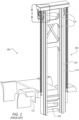
- Figure 1 is an isometric illustration of a frame 115 and mast system 200 for a conventional reach/lift truck 100.
- Figure 2 is a cross-sectional view of the mast system 200 of Figure 1 .
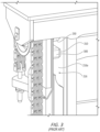
- Figure 3 is a close-up view of area A of the mast system 200 of Figure 1 .
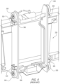
- Figure 4 is an isometric illustration of a carriage 220 that can be attached to the mast system 200 of Figure 1 .
- Figure 5 is a close-up view of a conventional wear block 300 and wear pad 310 arranged on the carriage 220 of Figure 4 .
- Figure 6A is an isometric illustration of the conventional wear block 300 and wear pad 310 of Figure 5 .
- figure 6B is a cross-sectional view of the wear block 300 and wear pad 310 of Figure 6 .
- a conventional lift truck 100 has a frame 115 on which a mast system 200 is arranged.
- Conventional mast or lift systems 200 comprise carriages 220 having lift forks (not shown) mounted to the carriages 220.
- the carriages 220 are raised and lowered along the masts 210 to pick and carry loads. Forward and rearward forces on the carriage 220 are absorbed by rollers (or guide bearings) 230 mounted on the carriage 220 and arranged within the mast channel 214.
- a desired amount of clearance is provided between the rollers 230 and the front and rear channel sidewalls such that only one sidewall or the other contacts the roller 230 in response to a forward or rearward force on the carriage 220 to absorb the force and keep the rollers 230 positioned within the mast channel 214 as the carriage 220 is raised and lowered.
- Top and bottom wear blocks 300 are arranged on the carriage 220 between the carriage 220 and the mast channel inner wall 214a to keep the inner wall 214a of the mast channel 214 from impacting directly against the carriage components, such as the carriage rollers 230.
- the wear blocks 300 are generally arranged as far apart as possible (typically close to the carriage rollers 230) to absorb side-to-side (sideways) forces on the carriage 220 that occur during lifting of loads or truck travel while carrying loads on the lift forks.
- the wear blocks 300 are attached to the carriage 220 by welding, bolts, or other mechanical or chemical connection.
- Wear pads 310 are arranged in the wear blocks 300 and secured by a threaded bolt 302 arranged through a hole 312 in the center of the wear pad 310 and threaded into a receiving hole 304 in the base of the wear block 300.
- wear blocks 300 can also be arranged at the top and bottom of additional mast channels 216 to absorb side-to-side forces on mast rails 212 and to keep mast channel walls 216a from impacting mast components such as rollers 230.
- the wear surface (outermost surface) 310a of the wear pad 310 must therefore be maintained at a desired distance (e.g., clearance) from the channel wall 214a, 216a to absorb the sideways forces without impairing the lift operation.
- a desired distance e.g., clearance
- the wear pads 310 are designed to wear down over time, the distance between the wear pad 310 and the channel wall 214a, 216a is difficult to maintain at a constant level. If the clearance is too great, it can permit too much play (side-to-side movement) of the carriage 220 and/or mast rails 212 as they are raised and lowered, causing additional wear on the lift components.
- wear pads 310 wear out completely, metal-to-metal contact can occur that can damage mast or carriage components. As noted previously, however, conventional wear pads 310 may be difficult to access to service, adjust, or replace.
- Figure 7 is an isometric view of a wear block 400 and wear pad 410 according to principles of the present inventive concepts, shown mounted on a carriage 220.
- Figure 8 is a cross-sectional top view of a mast system 200 showing wear blocks 400 and wear pads 410 arranged on a carriage 220 and mast rail 210 in mast channels 214, 216 according to principles of the present inventive concepts.
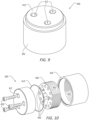
- Figure 9 is an isometric illustration of an adjustable wear block 400 according to principles of the present inventive concepts.
- Figure 10 is an exploded isometric illustration of the adjustable wear block 400 of Figure 9 .
- Figure 11 is an isometric view of the housing 402 and base 404 of the adjustable wear block 400 of Figure 10 .
- Figure 12 is a cross-sectional isometric view of the adjustable wear block 400 of Figure 9 .
- a wear block 400 is designed and mounted to a carriage 220 or mast rail 210 in a manner that permits the wear pad 410 height to be easily adjusted to position the wear surface 410a of the wear pad 410 at a proper distance (clearance) from the opposite channel wall 214a, 216a to absorb sideways forces and to prevent damage to mast components without interfering with lift operations.
- an adjustable wear block 400 having an easily adjustable wear surface 410a position (or wear pad height, a distance away from a surface).
- a circular housing 402 having internal threads 403 is attached to the carriage 220 so as to be arranged between the carriage 220 and a mast channel wall 214a when the carriage 220 is mounted in the mast system 200.
- the wear block housing 402 can be attached to the carriage 220 by welding, bolts, adhesive, or other mechanical or chemical connection.
- a threaded base 404 (formed of metal or other rigid material) having threads 405 matching the housing threads 403 is arranged in the housing 402 such that its position within the housing 402 can be adjusted by rotating the metal base 404 with respect to the housing 402.
- a wear pad 410 is attached to the base 404 using one or more fasteners, an adhesive, or other connection mechanism.
- three threaded bolts 430 are secured through holes 412 in the wear pad 410 to mounting holes 406 in the base 404 to secure the wear pad 410 to the rotatable base 404.
- a hexagonal hole or other tool receptacle 408 can be arranged in or through a center of the base 404 to permit a tool (such as a hex wrench or other tool) 440 (see Figures 13E-13F ) to be inserted therein to rotate the base 404 with respect to the housing 402.
- the adjustable wear block 400 can be made to easily retrofit to existing lift trucks 100 such as by replicating a connection mechanism of the conventional wear block 300.
- screw holes can be arranged in locations on the adjustable wear block that match the mounting screws on or through the carriage or mast mounting surface. Additional holes can be formed through the carriage or mast mounting wall to provide access to the locking holes and tool receptacle.
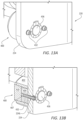
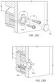
- Figures 13A-13F are isometric and isometric cross-sectional views of the adjustable wear block 400 of Figure 9 arranged on a wall 224 of a carriage 220, further illustrating a method for adjusting the adjustable wear block 400 according to principles of the present inventive concepts.
- a tool receptacle hole 224a can be arranged through the mounting wall 224 of the carriage 220 or mast rail 210 to permit easy adjustment of the wear pad 410 height using a tool 440, without the need to remove the carriage 220 or other mast system 200 components.
- One or more locking holes 407 can be provided in the bottom of the base 404 to receive one or more locking screws or pins 432 that prevent rotation of the base 404 when the locking screws 432 are inserted through a mounting wall 224 into the locking holes 407.
- the locking holes 407 can, for instance, be arranged in a circular pattern near an outside edge of the base 404 to permit the base 404 to be locked in any of numerous different rotational positions.
- the locking screws 432 can, for instance, be threaded bolts that are threaded into the threaded locking holes 407.
- Matching holes 224b can be arranged through the carriage or mast sidewall 224 to which the wear block 410 is attached to receive the locking screws or pins 432.
- a clearance of the wear pad 410 can be set to a desired distance by first adjusting the wear pad 410 to a height where the wear surface 410a contacts the mast channel wall 214a, 216a (by rotating the tool clockwise as indicated in Figure 13E ) and then rotating the base 404 backwards (by rotating the tool counterclockwise as indicated in Figure 13F ) by some amount (e.g., two full rotations of the adjustment tool 440 (and therefore the base 404)).
- a sticker 442 or other markings can be placed around the hole 224a for the adjustment tool 440 with divisions 444 indicating a relationship between the rotation of the tool 440 and the height adjustment (or linear travel distance) of the wear pad 410.
- the base threads 405 and housing threads 403 each have a 6 mm thread pitch and each segment 444 on the sticker 442 can represent 0.5 mm of linear travel of the wear pad 410.
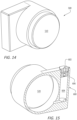
- Figure 14 is an isometric view of a hydraulic adjustable wear block 500 according to another embodiment of principles of the present inventive concepts.
- Figure 15 is a cross-sectional view of the hydraulic adjustable wear block 500 of Figure 14 .
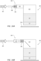
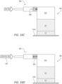
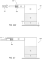
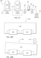
- Figures 16A-16E are schematic illustrations of the hydraulic adjustable wear block 500, illustrating a method of operating the hydraulic adjustable wear block 500 according to further principles of the present inventive concepts.
- a wear pad 510 can be hydraulically adjusted to maintain a desired clearance with the mast channel wall 214a.
- a wear pad 510 is arranged on a hydraulic piston 520 within a wear block 500.
- the wear pad 510 and hydraulic piston 520 can, for example, be the same size and shape in cross-section, or the hydraulic piston 520 can be arranged to push a base plate or wear pad of any other desired shape.
- the wear pad 510 itself may be the hydraulic piston 520.
- a hydraulic fluid valving system 600 may be provided that ensures that the wear pad 510 is arranged with the desired clearance C from the mast channel wall 214a.
- An oil feed 602 can be provided to feed oil (or other suitable hydraulic fluid) into the hydraulic cylinder 610 behind the hydraulic piston 520 that drives the wear pad 510.
- the oil feed 602 is preferably supplied through a first cylinder 604 having a piston 606 arranged therein that can slide forward and backward throughout the length of the first cylinder 604.
- the first cylinder 604 can have a fluid volume defined such that one stroke of the piston 606 corresponds to a predetermined linear travel distance of the wear pad 510.
- the predetermined linear travel distance can, for example, be approximately about 2 mm.
- a check valve 608 can be arranged through the piston 606 so that oil is supplied through the piston 606 into the hydraulic cylinder 610 once the piston 606 travels fully forward within the first cylinder 604.
- the check valve 608 can include a preload spring 609 that requires a predetermined force (pressure) before opening.
- the predetermined pressure can, for instance, be approximately about 1 bar.
- the check valve 608 prevents oil from returning back into the oil feed 602.
- Figure 17 is a schematic illustration of a hydraulic adjustable wear block 500A according to yet another embodiment of the present inventive concepts.
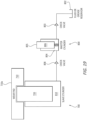
- Figure 18 is a schematic illustration of a hydraulic adjustable wear block 500B according to a still further embodiment of the present inventive concepts.
- Figure 19 is a schematic illustration of an automatically adjusting wear block 700 according to another embodiment of the present inventive concepts.
- the amount of clearance C can be made adjustable by providing extra volume in the first cylinder 604.
- the first cylinder 604 can be provided with additional volume and an adjusting screw 612 or other travel limiter to set the travel distance of the first piston 606 and therefore the corresponding linear travel distance of the wear pad 510.
- the clearance C can be adjusted and set as desired.
- a second piston (centering piston) 616 can be provided that acts as or controls a valve 620 to control when the oil is supplied to the hydraulic cylinder 610, such as when a mast 210 is centered.
- the second piston 616 can be arranged in a second cylinder 614 with a retraction spring 618 biasing it toward a closed valve position.
- the oil feed 602 can be selectively supplied to the first cylinder 604 through the second cylinder 614 only when the second piston 616 opens the valve 620.
- the second piston 616 can open the valve 620 to permit oil to flow into the first cylinder 604.
- Figure 19 is a schematic illustration of an automatically adjusting wear block 700 according to another embodiment of the present inventive concepts.
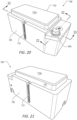
- Figure 20 is an isometric illustration of the automatically adjusting wear block 700 according to additional principles of the present inventive concepts.
- Figure 21 is another isometric illustration of the automatically adjusting wear block 700 of Figure 20 .
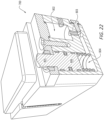
- Figure 22 is a cross-sectional isometric illustration of the automatically adjusting wear block 700 of Figure 20 .
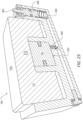
- Figure 23 is another cross-sectional isometric illustration of the automatically adjusting wear block 700 of Figure 20 .
- an automatically adjusting wear block 700 can be provided that automatically adjusts a height of the wear pad 710 to provide a desired clearance with the mast channel wall 214a at a predetermined travel point of the mast system 200.
- an automatically adjusting wear block 700 can include a wear block housing 702, a wear pad 710 arranged in the housing 702, and a hydraulic system 800 for adjusting the height of the wear pad 710.
- a button 805 can be arranged on the wear block housing 702 beside the wear pad 710 to force the wear pad 710 outward when depressed.
- a ramp 910 can be provided along the mast channel 214, 216 to activate the button 805 when the carriage/mast 220/210 reaches a certain desired adjustment point along its travel.
- a hydraulic piston 806 in a master cylinder 804 is connected to a button 805.
- a ramp 910 in the mast channel 214, 216 is configured to contact the button 805 at the desired adjustment point during carriage/mast 220/210 travel.
- the button 805 is depressed and the connected hydraulic piston 806 forces hydraulic fluid from the master cylinder 804 into a slave cylinder 810, driving a second hydraulic piston 720 that forces the wear pad 710 outward.
- Retention springs 712 can be provided between the wear block housing 702 and wear pad 710 to keep the wear pad 710 inside the wear block housing 702.
- a shim plate 920 can be provided in the mast channel 214, 216 at the adjustment point in the carriage/mast 220/210 travel to ensure that the wear pad surface 710a extends only to the shim plate 920. This keeps the appropriate clearance between the upper surface 710a of the wear pad 710 and the mast channel wall 214a.
- Check valves 803, 808 can be provided between the fluid reservoir 802 and the master cylinder 804 and between the master cylinder 804 and the slave cylinder 810 to ensure that the hydraulic fluid only flows in one direction.
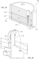
- the piston 1220 and wear pad 1210 are slidably arranged in a receptacle (cylinder) 1240 of the wear block 1200.
- the one or more O-rings 1230, 1232 are arranged around the piston to seal against the wall of the receptacle 1240 to prevent hydraulic oil or grease from leaking.
- the oil/grease fitting 1242 is arranged at a bottom of the wear block 1200 to supply oil/grease to the receptacle 1240 to drive the piston 1220 and the connected wear pad 1210 outward until it contacts a shim plate (not shown) or otherwise reaches a desired position.
- An operator can use a grease gun or other hydraulic fluid supply (i.e., hydraulic pump) to force oil/grease into the grease points 1300 and through the grease lines 1310, 1312 to drive pistons in the wear blocks 1320 outward.
- Shim plates can be used to provide a stop point for the outward movement of the wear pads 1320 and ensure a proper clearance with the channel walls 214a, 216a.
- one or more of the methods described with respect to Figures 16A-18 can be used to automatically set the proper clearance.
Landscapes
- Engineering & Computer Science (AREA)
- Mechanical Engineering (AREA)
- Structural Engineering (AREA)
- Transportation (AREA)
- General Engineering & Computer Science (AREA)
- Life Sciences & Earth Sciences (AREA)
- Geology (AREA)
- Civil Engineering (AREA)
- Physics & Mathematics (AREA)
- Fluid Mechanics (AREA)
- Forklifts And Lifting Vehicles (AREA)
Applications Claiming Priority (1)
| Application Number | Priority Date | Filing Date | Title |
|---|---|---|---|
| US18/207,879 US12522482B1 (en) | 2023-06-09 | 2023-06-09 | Adjustable wear block for mast systems |
Publications (1)
| Publication Number | Publication Date |
|---|---|
| EP4484357A1 true EP4484357A1 (fr) | 2025-01-01 |
Family
ID=91226972
Family Applications (1)
| Application Number | Title | Priority Date | Filing Date |
|---|---|---|---|
| EP24177417.3A Pending EP4484357A1 (fr) | 2023-06-09 | 2024-05-22 | Bloc d'usure réglable pour systèmes de mât |
Country Status (3)
| Country | Link |
|---|---|
| US (1) | US12522482B1 (fr) |
| EP (1) | EP4484357A1 (fr) |
| CN (1) | CN119100307A (fr) |
Citations (3)
| Publication number | Priority date | Publication date | Assignee | Title |
|---|---|---|---|---|
| US4417769A (en) * | 1982-03-29 | 1983-11-29 | Towmotor Corporation | Self adjusting bearing arrangement |
| CA1299528C (fr) * | 1988-04-29 | 1992-04-28 | M.W. Kenneth Nunweiler | Roulement anti-fro-tement reglable |
| EP3209596B1 (fr) * | 2014-10-24 | 2022-07-27 | CIJ Engineered Pty Ltd | Plaque d'usure pour bras télescopique |
Family Cites Families (22)
| Publication number | Priority date | Publication date | Assignee | Title |
|---|---|---|---|---|
| GB190930254A (en) | 1909-12-28 | 1910-03-31 | Philip Seymour Robinson | Improvements in Bearings for the Horizontal Cutter Spindles of Wood Planing, Moulding and similar Machines. |
| GB309691A (en) | 1928-03-05 | 1929-04-18 | Edgar Garbutt Taylor | Improvements in side block bearings for the ends or necks of machine bowls or rollers, applicable also to shafting |
| JPS58500439A (ja) | 1981-03-16 | 1983-03-24 | トウモ−タ− コ−ポレ−シヨン | 調節可能なスライダ軸受組立体 |
| SE460116B (sv) | 1985-02-01 | 1989-09-11 | Jungheinrich Kg | Transportdon, i synnerhet staplingsfordon |
| KR890001401Y1 (ko) * | 1985-10-30 | 1989-04-05 | 대우중공업주식회사 | 지게차용 마스트 실린더 완충장치 |
| US4759452A (en) | 1987-02-20 | 1988-07-26 | Faint Richard C | Articulated load bearing wear pad assembly |
| DE3801101C2 (de) | 1988-01-16 | 1996-02-01 | Kaup Gmbh & Co Kg | Anbaugerät mit einer Andruck- und Spielausgleichsvorrichtung für einen Hublader |
| US5183018A (en) | 1992-03-24 | 1993-02-02 | Cummins Engine Co., Inc. | Master cylinder with two-piece master piston |
| GB2375753B (en) | 2001-03-24 | 2004-11-17 | Bamford Excavators Ltd | Wear pad |
| FR2845678A1 (fr) * | 2002-09-06 | 2004-04-16 | Linde Ag | Equipement de levage a patins comme moyens de guidage pour un chariot elevateur |
| GB0718050D0 (en) | 2007-09-15 | 2007-10-24 | Bryce John M | Post drivers |
| US9061871B2 (en) * | 2010-09-01 | 2015-06-23 | Oiles Corporation | Mast assembly for forklift truck |
| US8517440B1 (en) | 2012-04-09 | 2013-08-27 | Cascade Corporation | Carton clamp arm with adjustable pivot block |
| ITMO20130158A1 (it) | 2013-05-31 | 2014-12-01 | Cnh Italia Spa | Dispositivo anti-usura regolabile per un braccio telescopico. |
| US10550886B2 (en) * | 2016-07-14 | 2020-02-04 | Cascade Corporation | Nonmetallic bearing on bearing assembly |
| US10066363B1 (en) | 2017-07-13 | 2018-09-04 | Cnh Industrial America Llc | Wear pad system |
| CN210859608U (zh) | 2019-11-11 | 2020-06-26 | 杭州诚信汽车轴承有限公司 | 用于操纵摩擦离合器的液压分离系统的从动缸 |
| US11111957B1 (en) * | 2020-07-22 | 2021-09-07 | Zoomlion Heavy Industry Na, Inc. | Wear pad |
| US11041526B1 (en) | 2020-07-25 | 2021-06-22 | Zoomlion Heavy Industry NA, Inc | Adjustable wear pad |
| CN212764437U (zh) | 2020-08-07 | 2021-03-23 | 温州宏福模具制造有限公司 | 一种eva2次成型两开模 |
| GB2609669B (en) * | 2021-08-13 | 2023-10-25 | Caterpillar Inc | Wear pad assembly and method for adjusting |
| US11772209B1 (en) * | 2022-04-22 | 2023-10-03 | Swanson Industries, Inc. | Mining shield base lift apparatuses and methods |
-
2023
- 2023-06-09 US US18/207,879 patent/US12522482B1/en active Active
-
2024
- 2024-05-22 EP EP24177417.3A patent/EP4484357A1/fr active Pending
- 2024-06-07 CN CN202410735921.6A patent/CN119100307A/zh active Pending
Patent Citations (3)
| Publication number | Priority date | Publication date | Assignee | Title |
|---|---|---|---|---|
| US4417769A (en) * | 1982-03-29 | 1983-11-29 | Towmotor Corporation | Self adjusting bearing arrangement |
| CA1299528C (fr) * | 1988-04-29 | 1992-04-28 | M.W. Kenneth Nunweiler | Roulement anti-fro-tement reglable |
| EP3209596B1 (fr) * | 2014-10-24 | 2022-07-27 | CIJ Engineered Pty Ltd | Plaque d'usure pour bras télescopique |
Also Published As
| Publication number | Publication date |
|---|---|
| US12522482B1 (en) | 2026-01-13 |
| CN119100307A (zh) | 2024-12-10 |
Similar Documents
| Publication | Publication Date | Title |
|---|---|---|
| JPS6331786Y2 (fr) | ||
| US7308971B2 (en) | Turn plate and slip plate centering and locking mechanism | |
| US11124398B2 (en) | Tilt-safe, high-capacity lift device | |
| JP5631020B2 (ja) | 平板状被検査体の試験装置 | |
| US10214399B2 (en) | Tilt-safe, high-capacity, bottle jack system and method | |
| US20090273233A1 (en) | Modular track tensioning system | |
| DE10207605C1 (de) | Reibgehemme mit Drillingskolbenentlastung | |
| US4750524A (en) | Apparatus for interchanging orifice plates for orifice flowmeter | |
| US12522482B1 (en) | Adjustable wear block for mast systems | |
| EP0893624A1 (fr) | Dispositif de transmission | |
| US12228244B2 (en) | Mechanical apparatus levelling mechanism and levelling method therefor | |
| CN106378706A (zh) | 滑块式伸缩自定心液压中心架 | |
| US20040237623A1 (en) | Compensating die holder | |
| DE10017507B4 (de) | Ausrichtvorrichtung für Schwerlasten und Verfahren zum Ausrichten von Schwerlasten | |
| CN111924747A (zh) | 水平运动顶升装置 | |
| US6273215B1 (en) | Multi vehicle position cantilevered lift | |
| DE3318434C2 (fr) | ||
| CN111943075B (zh) | 随动自锁三维千斤顶 | |
| EP0107228A1 (fr) | Mécanisme de verrouillage pour une cabine basculante de camion | |
| CN100479982C (zh) | 机床自动托板交换机 | |
| KR100554897B1 (ko) | 스크린 인쇄장치 | |
| US5443000A (en) | Calender | |
| CN118003070A (zh) | 一种用于铁路货车制动阀的智能组装系统主阀变位单元 | |
| US11713228B2 (en) | Tilt-safe, high-capacity lift device | |
| EP1097014B1 (fr) | Dispositif et procede servant a reguler l'ecoulement d'un metal en fusion |
Legal Events
| Date | Code | Title | Description |
|---|---|---|---|
| PUAI | Public reference made under article 153(3) epc to a published international application that has entered the european phase |
Free format text: ORIGINAL CODE: 0009012 |
|
| STAA | Information on the status of an ep patent application or granted ep patent |
Free format text: STATUS: THE APPLICATION HAS BEEN PUBLISHED |
|
| AK | Designated contracting states |
Kind code of ref document: A1 Designated state(s): AL AT BE BG CH CY CZ DE DK EE ES FI FR GB GR HR HU IE IS IT LI LT LU LV MC ME MK MT NL NO PL PT RO RS SE SI SK SM TR |
|
| STAA | Information on the status of an ep patent application or granted ep patent |
Free format text: STATUS: REQUEST FOR EXAMINATION WAS MADE |
|
| 17P | Request for examination filed |
Effective date: 20250627 |
|
| STAA | Information on the status of an ep patent application or granted ep patent |
Free format text: STATUS: EXAMINATION IS IN PROGRESS |