EP4484390A1 - Composition de verre, article en verre fabriqué à partir de la composition de verre, procédé de fabrication d'un article en verre et dispositif d'affichage - Google Patents
Composition de verre, article en verre fabriqué à partir de la composition de verre, procédé de fabrication d'un article en verre et dispositif d'affichage Download PDFInfo
- Publication number
- EP4484390A1 EP4484390A1 EP24183375.5A EP24183375A EP4484390A1 EP 4484390 A1 EP4484390 A1 EP 4484390A1 EP 24183375 A EP24183375 A EP 24183375A EP 4484390 A1 EP4484390 A1 EP 4484390A1
- Authority
- EP
- European Patent Office
- Prior art keywords
- glass
- glass article
- mol
- article
- display device
- Prior art date
- Legal status (The legal status is an assumption and is not a legal conclusion. Google has not performed a legal analysis and makes no representation as to the accuracy of the status listed.)
- Pending
Links
Images







Classifications
-
- C—CHEMISTRY; METALLURGY
- C03—GLASS; MINERAL OR SLAG WOOL
- C03C—CHEMICAL COMPOSITION OF GLASSES, GLAZES OR VITREOUS ENAMELS; SURFACE TREATMENT OF GLASS; SURFACE TREATMENT OF FIBRES OR FILAMENTS MADE FROM GLASS, MINERALS OR SLAGS; JOINING GLASS TO GLASS OR OTHER MATERIALS
- C03C3/00—Glass compositions
- C03C3/04—Glass compositions containing silica
- C03C3/076—Glass compositions containing silica with 40% to 90% silica, by weight
- C03C3/083—Glass compositions containing silica with 40% to 90% silica, by weight containing aluminium oxide or an iron compound
- C03C3/085—Glass compositions containing silica with 40% to 90% silica, by weight containing aluminium oxide or an iron compound containing an oxide of a divalent metal
-
- C—CHEMISTRY; METALLURGY
- C03—GLASS; MINERAL OR SLAG WOOL
- C03B—MANUFACTURE, SHAPING, OR SUPPLEMENTARY PROCESSES
- C03B21/00—Severing glass sheets, tubes or rods while still plastic
- C03B21/02—Severing glass sheets, tubes or rods while still plastic by cutting
-
- C—CHEMISTRY; METALLURGY
- C03—GLASS; MINERAL OR SLAG WOOL
- C03B—MANUFACTURE, SHAPING, OR SUPPLEMENTARY PROCESSES
- C03B27/00—Tempering or quenching glass products
- C03B27/02—Tempering or quenching glass products using liquid
- C03B27/03—Tempering or quenching glass products using liquid the liquid being a molten metal or a molten salt
-
- C—CHEMISTRY; METALLURGY
- C03—GLASS; MINERAL OR SLAG WOOL
- C03C—CHEMICAL COMPOSITION OF GLASSES, GLAZES OR VITREOUS ENAMELS; SURFACE TREATMENT OF GLASS; SURFACE TREATMENT OF FIBRES OR FILAMENTS MADE FROM GLASS, MINERALS OR SLAGS; JOINING GLASS TO GLASS OR OTHER MATERIALS
- C03C15/00—Surface treatment of glass, not in the form of fibres or filaments, by etching
-
- C—CHEMISTRY; METALLURGY
- C03—GLASS; MINERAL OR SLAG WOOL
- C03C—CHEMICAL COMPOSITION OF GLASSES, GLAZES OR VITREOUS ENAMELS; SURFACE TREATMENT OF GLASS; SURFACE TREATMENT OF FIBRES OR FILAMENTS MADE FROM GLASS, MINERALS OR SLAGS; JOINING GLASS TO GLASS OR OTHER MATERIALS
- C03C15/00—Surface treatment of glass, not in the form of fibres or filaments, by etching
- C03C15/02—Surface treatment of glass, not in the form of fibres or filaments, by etching for making a smooth surface
-
- C—CHEMISTRY; METALLURGY
- C03—GLASS; MINERAL OR SLAG WOOL
- C03C—CHEMICAL COMPOSITION OF GLASSES, GLAZES OR VITREOUS ENAMELS; SURFACE TREATMENT OF GLASS; SURFACE TREATMENT OF FIBRES OR FILAMENTS MADE FROM GLASS, MINERALS OR SLAGS; JOINING GLASS TO GLASS OR OTHER MATERIALS
- C03C21/00—Treatment of glass, not in the form of fibres or filaments, by diffusing ions or metals in the surface
-
- C—CHEMISTRY; METALLURGY
- C03—GLASS; MINERAL OR SLAG WOOL
- C03C—CHEMICAL COMPOSITION OF GLASSES, GLAZES OR VITREOUS ENAMELS; SURFACE TREATMENT OF GLASS; SURFACE TREATMENT OF FIBRES OR FILAMENTS MADE FROM GLASS, MINERALS OR SLAGS; JOINING GLASS TO GLASS OR OTHER MATERIALS
- C03C21/00—Treatment of glass, not in the form of fibres or filaments, by diffusing ions or metals in the surface
- C03C21/001—Treatment of glass, not in the form of fibres or filaments, by diffusing ions or metals in the surface in liquid phase, e.g. molten salts, solutions
- C03C21/002—Treatment of glass, not in the form of fibres or filaments, by diffusing ions or metals in the surface in liquid phase, e.g. molten salts, solutions to perform ion-exchange between alkali ions
-
- C—CHEMISTRY; METALLURGY
- C03—GLASS; MINERAL OR SLAG WOOL
- C03C—CHEMICAL COMPOSITION OF GLASSES, GLAZES OR VITREOUS ENAMELS; SURFACE TREATMENT OF GLASS; SURFACE TREATMENT OF FIBRES OR FILAMENTS MADE FROM GLASS, MINERALS OR SLAGS; JOINING GLASS TO GLASS OR OTHER MATERIALS
- C03C23/00—Other surface treatment of glass not in the form of fibres or filaments
-
- G—PHYSICS
- G09—EDUCATION; CRYPTOGRAPHY; DISPLAY; ADVERTISING; SEALS
- G09F—DISPLAYING; ADVERTISING; SIGNS; LABELS OR NAME-PLATES; SEALS
- G09F9/00—Indicating arrangements for variable information in which the information is built-up on a support by selection or combination of individual elements
- G09F9/30—Indicating arrangements for variable information in which the information is built-up on a support by selection or combination of individual elements in which the desired character or characters are formed by combining individual elements
-
- G—PHYSICS
- G09—EDUCATION; CRYPTOGRAPHY; DISPLAY; ADVERTISING; SEALS
- G09F—DISPLAYING; ADVERTISING; SIGNS; LABELS OR NAME-PLATES; SEALS
- G09F9/00—Indicating arrangements for variable information in which the information is built-up on a support by selection or combination of individual elements
- G09F9/30—Indicating arrangements for variable information in which the information is built-up on a support by selection or combination of individual elements in which the desired character or characters are formed by combining individual elements
- G09F9/301—Indicating arrangements for variable information in which the information is built-up on a support by selection or combination of individual elements in which the desired character or characters are formed by combining individual elements flexible foldable or roll-able electronic displays, e.g. thin LCD, OLED
Definitions
- the present invention relates to a glass composition, a glass article made from the glass composition, a method of manufacturing of a glass article, and a display device.
- Glass articles are widely used in electronic devices including display devices, building materials, and the like.
- a glass article is applied to a substrate of a flat panel display device, such as a liquid crystal display (“LCD”), an organic light-emitting display device (“OLED”) or an electrophoretic display device, or to a cover window for protecting the display device.
- LCD liquid crystal display
- OLED organic light-emitting display device
- electrophoretic display device or to a cover window for protecting the display device.
- a desired glass article applied to a foldable display device may have a thin thickness to relieve bending stress when folded and at the same time may have sufficient strength to withstand external impacts. Accordingly, attempts are made to improve the strength of a thin glass article by changing the component ratio of a composition of the glass article and the conditions of a manufacturing process.
- the present invention provides a glass composition having a novel composition ratio, a glass article made from the glass composition, a method of manufacturing of a glass article, and a display device including the glass article.
- a glass article includes a glass composition including 60 mole percent (mol%) to 70 mol% of SiO 2 , 5 mol% to 15 mol% of Al 2 O 3 , 5 to 15 mol% of Na 2 O, greater than 0 mol% and equal to or less than 5 mol% of K 2 O, 5 to 15 mol% of Li 2 O, and greater than 0 mol% and equal to or less than 5 mol% of MgO, and satisfying Relation (1) below: 0.1 ⁇ Al 2 O 3 / sum of Na 2 O , K 2 O , and Li 2 O ⁇ 0.7 where Al 2 O 3 , Na 2 O, K 2 O, and Li 2 O in the Relation (1) denote contents (mol%) of Al2O3, Na2O, K2O, and Li2O, respectively, in the glass composition, and the glass article has a thickness of 100 micrometers ( ⁇ m) or less.
- a thickness of the glass article may be in a range of 20 ⁇ m to 100 ⁇ m.
- a thermal expansion coefficient of the glass article may be in a range of 90*10 -7 per kelvin (K -1 ) to 100*10 -7 K -1 .
- a glass transition temperature of the glass article may be in a range of 425 degrees Celsius (°C) to 525 °C.
- a density of the glass article may be in a range of 2.38 grams per cubic centimeter (g/cm 3 ) to 2.48 g/cm 3 .
- an elastic modulus of the glass article may be in a range of 72 gigapascals (GPa) to 82 GPa.
- a Poisson ratio of the glass article may be in a range of 0.20 to 0.22.
- a hardness of the glass article may be in a range of 5.50 GPa to 6.50 GPa.
- a fracture toughness of the glass article may be in a range of 0.75 megapascal square root meter (MPa*m 0.5 ) to 0.85 MPa*m 0.5.
- a brittleness of the glass article may be in a range of 7.0 ⁇ m -0.5 to 8.0 ⁇ m -0.5 .
- a surface roughness may be in a range of 0.2 nm to 0.45 nm or in a range of 0.2 nm to 0.4 nm.
- the glass article may be a foldable glass article.
- a glass composition includes 60 mol% to 70 mol% of SiO 2 , 5 mol% to 15 mol% of Al 2 O 3 , 5 mol% to 15 mol% of Na 2 O, greater than 0 mol% and equal to or less than 5 mol% of K 2 O, 5 mol% to 15 mol% of Li 2 O, and greater than 0 mol% and equal to or less than 5 mol% of MgO based on a total weight, and satisfies Relation (1) below: 0.1 ⁇ Al 2 O 3 / sum of Na 2 O , K 2 O , and Li 2 O ⁇ 0.7 where Al 2 O 3 , Na 2 O, K 2 O, and Li 2 O in the Relation (1) denote contents (mol%) of Al 2 O 3 , Na 2 O, K 2 O, and Li 2 O, respectively, in the glass composition.
- a display device includes a display panel including a plurality of pixels, a cover window disposed on the display panel, and an optically clear bonding layer disposed between the display panel and the cover window, where the cover window includes a glass composition including 60 mol% to 70 mol% of SiO 2 , 5 mol% to 15 mol% of Al 2 O 3 , 5 mol% to 15 mol% of Na 2 O, greater than 0 mol% and equal to or less than 5 mol% of K 2 O, 5 mol% to 15 mol% of Li 2 O, and greater than 0 mol% and equal to or less than 5 mol% of MgO, and satisfying Relation (1) below and having a thickness of 100 ⁇ m or less.
- Al 2 O 3 , Na 2 O, K 2 O, and Li 2 O in the Relation (1) denote contents (mol%) of Al 2 O 3 , Na 2 O, K 2 O, and Li 2 O, respectively, in the glass composition, and the cover window has a thickness of 100 ⁇ m or less.
- the cover window may have a thickness of 20 ⁇ m to 100 ⁇ m.
- the cover window may have a thermal expansion coefficient of 90*10 -7 K -1 to 100*10 -7 K -1 .
- the cover window may have a glass transition temperature of 425 °C to 525 °C.
- the cover window may have a density of 2.38 g/cm 3 to 2.48 g/cm 3 .
- the cover window may have an elastic modulus of 72 GPa to 82 GPa.
- the cover window may have a Poisson ratio of 0.20 to 0.22.
- the cover window may have a hardness of 5.50 GPa to 6.50 GPa.
- the cover window may have a fracture toughness of 0.75 MPa*m 0.5 to 0.85 MPa*m 0.5 .
- the cover window may have a brittleness of 7.0 ⁇ m -0.5 to 8.0 ⁇ m -0.5 .
- the cover window may have a surface roughness of 0.2 nm to 0.45 nm or in a range of 0.2 nm to 0.4 nm.
- the display device may be a foldable display device.
- a method of manufacturing a glass article includes forming a glass composition into a glass having a plate shape, cutting the glass, first surface treating the glass, tempering the glass, and second surface treating the glass, where the glass composition includes a glass composition including 60 mol% to 70 mol% of SiO 2 , 5 mol% to 15 mol% of Al 2 O 3 , 5 mol% to 15 mol% of Na 2 O, greater than 0 mol% and equal to or less than 5 mol% of K 2 O, 5 mol% to 15 mol% of Li 2 O, and greater than 0 mol% and equal to or less than 5 mol% of MgO based on a total weight, and satisfying Relation (1) below.
- Al 2 O 3 , Na 2 O, K 2 O, and Li 2 O in the Relation (1) denote contents (mol%) of Al 2 O 3 , Na 2 O, K 2 O, and Li 2 O, respectively, in the glass composition.
- the first surface treating may be to etch the surface of the glass at an etching rate of 1 micrometer per minute ( ⁇ m/min) to 1.4 ⁇ m/min.
- the first surface treating may be to etch the surface of the glass by a thickness of 0.8 ⁇ m to 1.2 ⁇ m.
- the second surface treating may be to etch the surface of the glass at an etching rate of 1 ⁇ m/min to 1.4 ⁇ m/min.
- the second surface treating may be to etch the surface of the glass by a thickness of 0.2 ⁇ m to 0.8 ⁇ m.
- a surface roughness may be in a range of 0.2 nm to 0.45 nm or in a range of 0.2 nm to 0.4 nm.
- a glass composition in an embodiment may have a novel composition ratio of components, and a glass article made from the glass composition may have excellent mechanical strength, surface strength, and impact resistance properties while having flexibility.
- the display device including a glass article described above may have excellent flexibility and strength to the extent that it may be applied to a foldable display device.
- FIG. 1 is a perspective view of an embodiment of glass articles.
- Glass is used as a cover window for protecting a display, a substrate for a display panel, a substrate for a touch panel, an optical member such as a light guide plate, etc. in electronic devices including displays such as tablet personal computers ("PCs"), notebook PCs, smartphones, electronic books, televisions and PC monitors as well as refrigerators and washing machines including display screens.
- the glass may also be used for cover glass of vehicle dashboards, cover glass of solar cells, building interior materials, and windows of buildings or houses.
- Glass is desired to have great strength.
- glass for windows is desired to be thin to have relatively high transmittance and light weight but desired to be strong enough not to be easily broken by an external impact, for example.
- Glass with increased strength may be produced using a method such as chemical tempering or thermal tempering.
- tempered glass having various shapes are illustrated in FIG. 1 .
- a glass article 100 may be in the shape of a flat sheet or a flat plate.
- glass articles 101 through 103 may have a three-dimensional ("3D") shape including a bent portion.
- a glass article may have edges of a flat portion bent (refer to ⁇ 101'), may be generally curved (refer to '102'), or may be folded (refer to ⁇ 103'), for example.
- the glass article 100 may be shaped like a flat sheet or a flat plate but may have flexibility so that it may be a foldable glass article that may be folded or bent.
- the glass article 100 may be stretched or rolled.
- the glass articles 100 through 103 may have a rectangular planar shape. However, the glass articles 100 through 103 are not limited to the rectangular planar shape and may also have various planar shapes such as a rectangle with rounded corners, a square, a circle, and an oval. In the following embodiments, a flat plate having a rectangular planar shape will be described in an embodiment of the glass articles 100 through 103. However, it is clear that the invention is not limited thereto.
- the glass articles 100 through 103 may each include a first surface US, a second surface RS, and side surfaces SS.
- FIG. 2 is a perspective view illustrating an embodiment of an unfolded state of a display device to which a glass article is applied.
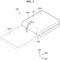
- FIG. 3 is a perspective view illustrating a folded state of the display device of FIG. 2 .
- a display device 500 in the embodiment may be a foldable display device.
- the glass article 100 of FIG. 1 may be applied to the display device 500 as a cover window.
- the glass article 100 may have flexibility so that it may be folded.
- a first direction DR1 may be a direction parallel to a side of the display device 500 in a plan view, e.g., a horizontal direction of the display device 500.
- a second direction DR2 may be a direction parallel to another side of the display device 500 in contact with the above side in a plan view, e.g., a vertical direction of the display device 500.
- a third direction DR3 may be a thickness direction of the display device 500.
- the display device 500 may be quadrangular, e.g., rectangular in a plan view.
- the display device 500 may be shaped like a rectangle with perpendicular corners or a rectangle with rounded corners in a plan view.
- the display device 500 may include two short sides disposed in the first direction DR1 and two long sides disposed in the second direction DR2 in a plan view.
- the display device 500 includes a display area DA and a non-display area NDA.
- the shape of the display area DA may correspond to the shape of the display device 500 in a plan view.
- the display area DA may also be quadrangular, e.g., rectangular, for example.
- the display area DA may include a plurality of pixels to display an image.
- the pixels may be arranged in a matrix direction. However, the invention is not limited thereto, and the pixels may be arranged in various other directions.
- Each of the pixels may be shaped like a rectangle, a rhombus, or a square in a plan view. However, the invention is not limited thereto. In an embodiment, each of the pixels may also be shaped like a quadrilateral other than a rectangle, a rhombus or a square, a circle, or an oval in a plan view, for example.
- the non-display area NDA may not display an image because it does not include pixels.
- the non-display area NDA may be disposed around the display area DA.
- the non-display area NDA may surround the display area DA.
- the invention is not limited thereto.
- the display area DA may also be partially surrounded by the non-display area NDA.
- the display device 500 may maintain both the folded state and the unfolded state.
- the display device 500 may be folded in an in-folding manner in which the display area DA is disposed inside as illustrated in FIG. 3 .
- portions of an upper surface of the display device 500 may face each other.
- the display device 500 may be folded in an out-folding manner in which the display area DA is disposed outside.
- portions of a lower surface of the display device 500 may face each other.
- the display device 500 may be a foldable device.
- foldable device is used to refer to devices that may be folded, including not only a folded device but also a device that may have both the folded state and the unfolded state.
- folding typically includes folding at an angle of about 180 degrees.
- the invention is not limited thereto, and folding at an angle of more than or less than 180 degrees, such as folding at an angle of 90 to less than 180 degrees or an angle of 120 to less than 180 degrees may also be understood as folding.
- even an incompletely folded state may also be also referred to as the folded state when it is not the unfolded state.
- a folded state at an angle of 90 degrees or less may be expressed as the folded state to distinguish it from the unfolded state as long as a maximum folding angle is 90 degrees or more, for example.
- the radius of curvature at the time of folding may be 5 millimeters (mm) or less, preferably, 1 mm to 2 mm or about 1.5 mm. However, the invention is not limited thereto.
- the display device 500 may include a folding area FDA, a first non-folding area NFA1, and a second non-folding area NFA2.
- the folding area FDA may be an area in which the display device 500 is folded
- the first non-folding area NFA1 and the second non-folding area NFA2 may be areas in which the display device 500 is not folded.
- the first non-folding area NFA1 may be disposed on a side, e.g., an upper side of the folding area FDA.
- the second non-folding area NFA2 may be disposed on the other side, e.g., a lower side of the folding area FDA.
- the folding area FDA may be an area bent with a predetermined curvature.
- the folding area FDA of the display device 500 may be set at a predetermined position.
- one folding area FDA or two or more folding areas FDA may be set at a predetermined position.
- the folding area FDA may not be limited to a predetermined position in the display device 500 but may be freely set in various areas.
- the display device 500 may be folded in the second direction DR2. As a result, a length of the display device 500 in the second direction DR2 may be reduced to about half. Therefore, a user may easily carry the display device 500.
- the direction in which the display device 500 is folded is not limited to the second direction DR2.
- the display device 500 may also be folded in the first direction DR1, for example.
- the length of the display device 500 in the first direction DR1 may be reduced to about half.
- each of the display area DA and the non-display area NDA overlaps the folding area FDA, the first non-folding area NFA1, and the second non-folding area NFA2.
- the invention is not limited thereto.
- each of the display area DA and the non-display area NDA may overlap at least one of the folding area FDA, the first non-folding area NFA1, and the second non-folding area NFA2, for example.
- FIG. 4 is a cross-sectional view illustrating an embodiment in which a glass article is applied as a cover window of a display device.
- the display device 500 may include a display panel 200, the glass article 100 disposed on the display panel 200 and serving as a cover window, and an optically clear bonding layer 300 disposed between the display panel 200 and the glass article 100 to bond the display panel 200 and the glass article 100 together.
- the display panel 200 may be, e.g., a self-luminous display panel such as an organic light-emitting display panel (“OLED”), an inorganic electroluminescent (“EL”) display panel, a quantum dot light-emitting display panel (“QED”), a micro-light-emitting diode (“LED”) display panel, a nano-LED display panel, a plasma display panel (“PDP”), a field emission display panel (“FED”) or a cathode ray tube (“CRT”) display panel or may be a light-receiving display panel such as a liquid crystal display (“LCD”) panel or an electrophoretic display (“EPD”) panel.
- OLED organic light-emitting display panel
- EL inorganic electroluminescent
- QED quantum dot light-emitting display panel
- LED micro-light-emitting diode
- nano-LED a plasma display panel
- PDP plasma display panel
- FED field emission display panel
- CRT cathode ray tube
- the display panel 200 may include a plurality of pixels PX and may display an image using light emitted from each pixel PX.
- the display device 500 may further include a touch member (not illustrated).
- the touch member may be internalized in the display panel 200.
- the touch member may be directly formed on a display member of the display panel 200 so that the display panel 200 itself may perform a touch function, for example.
- the touch member may be manufactured separately from the display panel 200 and then attached to an upper surface of the display panel 200 by an optically clear bonding layer.
- the glass article 100 is disposed on the display panel 200 to protect the display panel 200.
- the glass article 100 may be larger in size than the display panel 200.
- side surfaces of the glass article 100 may protrude outward from side surfaces of the display panel 200, but the invention is not limited to this case.
- the display device 500 may further include a printed layer (not illustrated) disposed on at least one surface of the glass article 100 in an edge portion of the glass article 100.
- the printed layer may prevent a bezel area of the display device 500 from being visible from the outside and, in some cases, may perform a decorative function.
- the optically clear bonding layer 300 is disposed between the display panel 200 and the glass article 100.
- the optically clear bonding layer 300 fixes the glass article 100 on the display panel 200.
- the optically clear bonding layer 300 may include an optical clear adhesive ("OCA”) or an optical clear resin (“OCR").
- the tempered glass article 100 described above will now be described in more detail.
- FIG. 5 is a cross-sectional view of a flat plate-shaped glass article.
- the glass article 100 may include a first surface US, a second surface RS, and side surfaces SS (refer to FIG. 1 ).
- the first surface US and the second surface RS of the flat plate-shaped glass article 100 are main surfaces having a relatively large area, and the side surfaces are outer surfaces connecting the first surface US and the second surface RS.
- the first surface US and the second surface RS face each other in the thickness direction.
- the light may usually be incident on any one of the first surface US and the second surface RS and then transmitted to the other surface.
- a thickness t of the glass article 100 is defined as a distance between the first surface US and the second surface RS.
- the thickness t of the glass article 100 may be in the range of, but not limited to, 100 ⁇ m or less, preferably be in the range of 20 ⁇ m to 100 ⁇ m. In an embodiment, the thickness t of the glass article 100 may be 80 ⁇ m or less. In another embodiment, the thickness t of the glass article 100 may be about 75 ⁇ m or less. In another embodiment, the thickness t of the glass article 100 may be about 70 ⁇ m or less. In another embodiment, the thickness t of the glass article 100 may be about 60 ⁇ m or less. In another embodiment, the thickness t of the glass article 100 may be about 65 ⁇ m or less.
- the thickness t of the glass article 100 may be about 50 ⁇ m or less. In another embodiment, the thickness t of the glass article 100 may be about 30 ⁇ m or less. In embodiments, the thickness t of the glass article 100 may be in the range of 20 ⁇ m to 50 ⁇ m or may have a value of about 30 ⁇ m.
- the glass article 100 may have a uniform thickness t. However, the invention is not limited thereto, and the glass article 100 may also have a different thickness t in each region.
- the glass article 100 may be tempered to have a predetermined stress profile therein.
- the glass article 100 after being tempered better prevents crack generation, crack propagation, and breakage due to an external impact than the glass article 100 before being tempered.
- the glass article 100 tempered through a tempering process may have various stresses in different regions.
- the stress values of the boundaries DOC1 and DOC2 between the compressive regions CSR1 and CSR2 and the tensile region CTR may be zero.
- the compressive stress in one compressive region CSR1 or CSR2 may have a different stress value according to position (i.e., depth from the surface).
- the tensile region CTR may have a different stress value according to depth from the surface US or RS.
- the first compressive region CSR1 and the second compressive region CSR2 may respectively include a first transition point TP1 and a second transition point TP2 at which the slope of the stress profile changes abruptly.
- the location of the compressive regions CSR1 and CSR2, the stress profile within the compressive regions CSR1 and CSR2, the compressive energy of the compressive regions CSR1 and CSR2, or the tensile energy of the tensile region CTR or the like may have a significant impact on the mechanical properties of the glass article 100, such as surface strength.
- FIG. 6 is a graph illustrating an embodiment of a stress profile of the glass article according to the embodiment of FIG. 5 .
- an x-axis represents the thickness direction of the glass article.
- compressive stress is represented by a positive value
- tensile stress is represented by a negative value.
- the magnitude of the compressive/tensile stress denotes the magnitude of an absolute value regardless of the sign of the value.
- the glass article 100 includes a first compressive region CSR1 extending (or expanding) from the first surface US to a first compression depth DOC1 and a second compressive region CSR2 extending (or expanding) from the second surface RS to a second compression depth DOC2.
- the tensile region CTR is disposed between the first compression depth DOC1 and the second compression depth DOC2.
- regions on both surface sides US and RS may be symmetrical to each other with respect to a center of the thickness t direction.
- compressive regions and a tensile region may also be disposed between facing side surfaces of the glass article 100 in a similar manner.
- the first compressive region CSR1 and the second compressive region CSR2 resist external impacts to prevent generation of cracks in the glass article 100 or breakage of the glass article 100.
- the compressive stresses of the first compressive region CSR1 and the second compressive region CSR2 tend to be greatest at the surfaces and decrease toward the inside of the glass article 100.
- the first compression depth DOC1 and the second compression depth DOC2 prevent cracks or grooves defined in the first and second surfaces US and RS from propagating to the tensile region CTR inside the glass article 100.
- Points corresponding to the first compression depth DOC1 and the second compression depth DOC2 correspond to the boundaries between the compressive regions CSR1 and CSR2 and the tensile region CTR and have a stress value of 0.
- the tensile stress of the tensile region CTR may be balanced with the compressive stresses of the compressive regions CSR1 and CSR2. That is, the total compressive stress (i.e., compressive energy) in the glass article 100 may be equal to the total tensile stress (i.e., tensile energy).
- the stress energy accumulated in one region having a predetermined width in the thickness t direction in the glass article 100 may be calculated by integrating a stress profile.
- the stress profile in the glass article 100 having a thickness of t is represented by a function f(x)
- the maximum tensile stress that meets the fragility criteria of the glass article 100 may satisfy, but not limited to, the following relation.
- a maximum tensile stress CT 1 may be 100 megapascals (Mpa) or less or may be 85 MPa or less.
- a maximum tensile stress CT 1 of 75 MPa or more may improve mechanical properties such as strength.
- the maximum tensile stress CT 1 may be, but is not limited to, 75 MPa to 85 MPa.
- the maximum tensile stress CT 1 of the glass article 100 may be generally disposed in a central portion of the glass article 100 in the thickness t direction. In an embodiment, the maximum tensile stress CT 1 of the glass article 100 may be disposed at a depth of 0.4 t to 0.6 t, at a depth of 0.45 t to 0.55 t, or at a depth of about 0.5 t, for example.
- the glass article 100 may be manufactured using a glass composition including predetermined components in a predetermined ratio. Depending on the composition ratio of the components included in the glass composition, the manufactured glass article 100 may have excellent strength and, at the same time, may have flexible nature and physical properties that make it applicable to a foldable display device.
- the glass composition that forms the glass article 100 may include 60 mole percent (mol%) to 70 mol% of SiO 2 , 5 mol% to 15 mol% of Al 2 O 3 , 5 mol% to 15 mol% of Na 2 O, greater than 0 mol% to 5 mol% of K 2 O, 5 mol% to 15 mol% of Li 2 O, and greater than 0 mol% to 5 mol% of MgO based on the total weight of the glass composition.
- SiO 2 may serve to form the framework of glass, increase chemical durability, and reduce generation of cracks when scratches (indentations) are formed on the glass surface.
- SiO 2 may be a network former oxide that forms a network of glass, and the glass article 100 manufactured to include SiO 2 may have a reduced coefficient of thermal expansion and improved mechanical strength.
- SiO 2 may be included in an amount of 60 mol% or more.
- SiO 2 may be included in the glass composition in an amount of 70 mol% or less.
- Al 2 O 3 serves to improve crushability of glass. That is, Al 2 O 3 may cause glass to be fragmented into a smaller number of pieces when the glass is broken.
- Al 2 O 3 may be an intermediate oxide that forms a bond with SiO 2 forming a network structure.
- Al 2 O 3 may act as an active component that improves ion exchange performance during chemical tempering and increases surface compressive stress after the tempering. When included in an amount of 5 mol% or more, Al 2 O 3 may effectively perform the above functions. To maintain acid resistance and meltability of glass, Al 2 O 3 may be included in an amount of 15 mol% or less.
- Na 2 O serves to form surface compressive stress through ion exchange and improve meltability of glass.
- Na 2 O may form non-bridging oxygen in a SiO 2 network structure by forming an ionic bond with oxygen of SiO 2 that forms the network structure.
- An increase in non-bridging oxygen may improve the flexibility of the network structure and cause the glass article 100 to have physical properties that make it applicable to a foldable display device.
- Na 2 O may effectively perform the above roles when included in an amount of 5 mol% or more. However, 15 mol% or less may be desirable in view of acid resistance of the glass article 100.
- K 2 O may replace Na with K to increase a compressive stress of the glass. Accordingly, K 2 O may contribute to realizing the flexible glass article 100 by improving folding reliability and the bending reliability of the glass article. K 2 O may meaningfully perform the function as described above when a content thereof is greater than 0 mol%. However, in terms of meltability of the glass article 100, it may be preferable that the content of K 2 O is 5 mol% or less.
- Li 2 O serves to form a surface compressive stress by ion exchange and improve meltability of the glass, similar to Na 2 O described above.
- Li 2 O may form non-bridging oxygen in the SiO 2 network structure by forming an ionic bond with oxygen of SiO 2 forming the network structure.
- An increase in the non-bridging oxygen may improve flexibility and a shock absorption function of the network structure, and the glass article 100 may have physical properties that it is applicable to the foldable display device. It is preferable in effectively performing the role as described above that a content of Li 2 O is 5 mol% or more. However, in terms of heat resistance of the glass article 100, it may be preferable that the content of Li 2 O is 15 mol% or less.
- MgO may improve a surface strength of glass and reduce a formation temperature of the glass.
- MgO may be a network modifier oxide modifying the SiO 2 network structure forming a network structure.
- MgO may decrease a refractive index of the glass and adjust a coefficient of thermal expansion and an elastic coefficient of the glass.
- MgO may meaningfully perform the function as described above when a content thereof is greater than 0 mol%. However, in terms of meltability of the glass article 100, it may be preferable that the content of MgO is 5 mol% or less.
- the glass composition may satisfy Relation (1) below. 0.1 ⁇ Al 2 O 3 / sum of Na 2 O , K 2 O , and Li 2 O ⁇ 0.7 where Al 2 O 3 , Na 2 O, K 2 O, and Li 2 O in Relation (1) denote contents (mol%) of Al 2 O 3 , Na 2 O, K 2 O, and Li 2 O. respectively.
- the value Al 2 O 3 /(sum of Na 2 O, K 2 O, and Li 2 O) may be also referred to as an R ratio.
- the glass article 100 manufactured using the glass composition in the embodiment may have characteristics and physical properties that make it applicable to a foldable display device.
- the glass article 100 may have flexibility so that it may be folded and unfolded and may have strength and chemical properties sufficient to make it applicable as a cover window of the display device 500, for example.
- a network structure formed by SiO 2 and Al 2 O 3 included in the glass composition may become a flexible network structure by the addition of Na 2 O, Li 2 O, and K 2 O.
- the addition of Na 2 O, Li 2 O, and K 2 O may cause Na ions, Li ions, or K ions to form ionic bonds with oxygen between bonds that form the network structure, e.g., bonds between SiO 2 , thereby increasing non-bridging oxygen.
- the increase in non-bridging oxygen in the network structure means that the bonds of the network structure are broken or open.
- the network structure of glass may have flexibility.
- the glass composition may include Na 2 O in an amount of 5 mol% or more, Li 2 O in an amount of 5 mol% or more, and K 2 O in an amount greater than 0 mol%, so that the manufactured glass article 100 may have sufficient flexibility.
- the glass composition may include Al 2 O 3 .
- the ratio of the Al 2 O 3 content to the sum of Na 2 O content, Li 2 O content, and K 2 O content may be adjusted within the range of 0.1 to 0.7 according to Relation (1) above. Accordingly, mechanical strength may be added to the network structure.
- the ratio (also referred to as R ratio) of the Al 2 O 3 content to the sum of Na 2 O content, Li 2 O content, and K 2 O content in the glass composition may be in the range of 0.1 to 0.7.
- Al 2 O 3 may have a tetrahedron crystal structure formed by SiO 2 .
- SiO 2 may have a tetrahedral crystal structure [SiO 4 ]
- Al 2 O 3 may also have a tetrahedral crystal structure [AlO 4 ] and a mechanical strength may be improved.
- the contents of Na 2 O, Li 2 O, and K 2 O compared to the contents of Al 2 O 3 may be formed at appropriate levels.
- the ratio (R ratio) of the Al 2 O 3 content to the sum of Na 2 O content, Li 2 O content, and K 2 O content in the glass composition is 0.1 or more
- the Na 2 O content, Li 2 O content, and K 2 O content may increase, and the increased Na 2 O, Li 2 O content, and K 2 O may break the SiO 2 network structure, thereby increasing the distance between atoms in the network structure. Accordingly, a lot of extra space may be formed in the SiO 2 network structure, and thus shock absorption characteristics and flexibility may be improved.
- the glass article 100 may have flexibility, sufficient strength against external impacts, and improved shock absorption characteristics.
- the glass composition may include 65.16 mol% of SiO 2 , 8.86 mol% of Al 2 O 3 , 9.72 mol% of Na 2 O, 3.2 mol% of K 2 O, 10.08 mol% of Li 2 O, and 2.99 mol% of MgO, and the R ratio according to Relation (1) above may be 0.385.
- the glass composition may, when desired, include components such as SnO 2 , Y 2 O 3 , La 2 O 3 , Nb 2 O 5 , Ta 2 O 5 and Gd 2 O 3 in addition to the components listed above.
- the glass composition may further include trace amounts of Sb 2 O 3 , CeO 2 , and/or As 2 O 3 as a refining agent.
- the glass composition having the above composition may be molded into the shape of plate glass using various methods known in the art. Once molded into the plate glass shape, the glass composition may be further processed to produce the glass article 100 that may be applied to the display device 500. However, the invention is not limited thereto, and the glass composition may also not be molded into the plate glass shape but may be directly molded into the glass article 100 applicable to a product without an additional molding process.
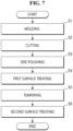
- FIG. 7 is a flowchart illustrating an embodiment of operations in a process of manufacturing a glass article.
- FIG. 8 is a schematic diagram illustrating a series of operations from a cutting operation to a second surface treating operation of FIG. 7 .
- a method of manufacturing a glass article 100 may include a molding operation (operation S1), a cutting operation (operation S2), a side polishing operation (operation S3), a first surface treating operation (operation S4), a tempering operation (operation S5), and a second surface treating operation (operation S6).
- the molding operation (operation S1) may include preparing a glass composition and molding the glass composition.
- the glass composition may have the above-described composition and components, which will not be described in detail here.
- the glass composition may be molded into a plate glass shape by a method such as a float process, a fusion draw process, or a slot draw process.
- the glass molded into the flat plate shape may be cut through the cutting operation (operation S2).
- the glass molded into the flat plate shape may have a size different from the size applied to a final glass article 100.
- glass may be molded in the state of a large-area substrate as a glass 10a of a mother substrate unit including a plurality of glass articles and then may be cut into a plurality of cells to produce a plurality of glass articles, for example.
- the final glass article 100 has a size of about 6 inches
- glass may be molded to a size (e.g., 120 inches) several to hundreds of times the size of the final glass article 100 and then cut to produce 20 flat plate shapes at once, for example. This may improve process efficiency as compared with when individual glass articles are molded separately.
- a desired shape may be formed through the cutting process.
- the cutting of the glass 10a of a mother substrate unit may be performed using a cutting knife 20, a cutting wheel, a laser, or the like.
- the glass cutting operation (operation S2) may be performed before the glass tempering operation (operation S5).
- the glass 10a corresponding to a mother substrate may also be tempered and then cut into final glass article sizes. In this case, however, cut surfaces (e.g., side surfaces) of the glass may not be tempered. Therefore, it is desirable to perform the tempering operation (operation S5) after completing the cutting operation (operation S2).
- a pre-tempering polishing operation may be performed between the glass cutting operation (operation S2) and the glass tempering operation (operation S5).
- the pre-tempering polishing operation may include the side polishing operation (operation S3) and the first surface treating operation (operation S4).
- the side polishing operation (operation S3) may be performed before the first surface treating operation (operation S4), but this order may be reversed.
- the side polishing operation (operation S3) is an operation of polishing side surfaces of the cut glass 10.
- the side surface of the glass 10 is polished to have a smooth surface.
- each side surface of the glass 10 may have a uniform surface through the side polishing operation (operation S3).
- the cut glass 10 may include one or more cut surfaces. In some cut glasses 10, two side surfaces of four side surfaces may be cut surfaces. In some other cut glasses 10, three side surfaces of four side surfaces may be cut surfaces. In some other cut glasses 10, all of four side surfaces may be cut surfaces. When the side surface is a cut surface, it may have different surface roughness from that of an uncut surface. In addition, even the cut surfaces may have different surface roughness. Therefore, by polishing each side surface through the side polishing operation (operation S3), each side surface may have uniform surface roughness or the like. Further, when there is a relatively small crack on the side surface, it may be removed through the side polishing operation (operation S3).
- the side polishing operation (operation S3) may be performed simultaneously on a plurality of cut glasses 10. That is, in a state where the plurality of cut glasses 10 are stacked, the stacked glasses 10 may be polished at the same time.
- the side polishing operation (operation S3) may be performed by a mechanical polishing method or a chemical mechanical polishing method using a polishing device 30.
- two opposite side surfaces of the cut glasses 10 may be polished simultaneously, and then the other two opposite side surfaces may be polished simultaneously, but the invention is not limited thereto.
- the first surface treating operation (operation S4) may heal the glasses 10.
- the reduced strength of the glass surface may be improved by first surface treating the cut glass 10.
- the first surface treating operation (operation S4) may be performed by accommodating the glasses 10 in a cassette and immersing the glasses 10 in a healing solution 40.
- the healing solution 40 may be a solution including or consisting of fluorine ions.
- the healing solution 40 may include or consist of at least one of hydrofluoric acid, sulfuric acid, hydrochloric acid, or ammonium fluoride, for example.
- the entirety of the surface of the glass 10 may be etched by the healing solution 40.
- Etching of the glass 10 may be performed at an etching rate of 1 micrometer per minute ( ⁇ m/min) to 1.4 ⁇ m/min, and may be performed with an etching thickness of the glass 10 in a range of 0.8 ⁇ m to 1.2 ⁇ m from the surface of the glass 10.
- the etching rate may be controlled by adjusting the concentration of the healing solution 40.
- the surface of the glass 10 may affect impact resistance properties in a state of having fine cracks. In the illustrated embodiment, it is possible to improve the impact resistance properties of the glass 10 by removing fine cracks of the glass 10 through etching.
- the glass tempering operation (operation S5) may be performed one or more times. In the following, performing the glass tempering operation (operation S5) three times is described as an example of, but the invention is not limited thereto, and the glass tempering operation (operation S5) may be performed once or twice.
- the first tempering operation includes a first ion exchange process in which the glass 10 is immersed in a first molten salt.
- the first molten salt may include or consist of sodium nitrate (NaNO 3 ) and potassium nitrate (KNO 3 ), the concentration of sodium (Na) ions in the cations in the molten salt may be 75 mol% to 25 mol%, and the concentration of potassium (K) ions may be 25 mol% to 75 mol%.
- the first ion exchange process may be performed for about 90 minutes to about 240 minutes at a temperature of approximately 385 degrees Celsius (°C) to 405 °C.
- lithium (Li) ions on the glass surface may be exchanged for sodium (Na) ions.
- glass including or consisting of lithium (Li) ions is exposed to sodium (Na) ions by a method such as immersing glass including or consisting of lithium (Li) ions in a molten salt tempering tank including or consisting of sodium nitrate (NaNO 3 )
- lithium (Li) ions of the glass surface are discharged to the outside and sodium (Na) ions may replace them. Since the exchanged sodium (Na) ions have a larger ionic radius than lithium (Li) ions, compressive stress may be generated. As the amount of exchanged sodium (Na) ions increases, compressive stress may increase.
- lithium (Li) ions may be eluted from the inside of the glass, and the sodium (Na) ion content in the mixed molten salt may generally decrease.
- the second tempering operation includes a second ion exchange process in which the glass 10 that has undergone the first tempering operation is immersed in a second molten salt.
- the second molten salt may include or consist of sodium nitrate (NaNO 3 ) and potassium nitrate (KNO 3 ), the content of sodium (Na) ions in the cations in the molten salt may be 5 mol% to 10 mol%, and the content of potassium (K) ions may be 90 mol% to 95 mol%.
- the second ion exchange process may be performed for about 30 minutes to about 120 minutes at a temperature of approximately 370 °C to 390 °C.
- the glass 10 including or consisting of sodium (Na) ions When the glass 10 including or consisting of sodium (Na) ions is exposed to potassium (K) ions by immersing it in a mixed molten salt bath including or consisting of potassium nitrate (KNO 3 ) and sodium nitrate (NaNO 3 ), sodium (Na) ions in the glass are discharged to the outside and the potassium (K) ions may replace them. Since the exchanged potassium (K) ions have a larger ionic radius than the sodium (Na) ions, it may generate compressive stress. The greater the amount of potassium (K) ions exchanged, the greater the compressive stress.
- the third tempering operation includes a third ion exchange process in which the glass that has undergone the second tempering operation is immersed in a third molten salt.
- the third molten salt includes potassium nitrate (KNO 3 ), and the concentration of potassium (K) ions in the cations in the molten salt may be 99.5 mol% to 100 mol%.
- the third ion exchange process may be performed for about 5 minutes to about 10 minutes at a temperature of approximately 370 °C to 390 °C.
- Sodium (Na) ions inside the glass that are not exchanged in the ion exchange process of the second tempering operation may be exchanged for potassium (K) ions.
- the ion exchange process may be performed on the surface of the glass.
- the second surface treating operation (operation S6) may be performed.
- the reduced strength of the glass surface may be improved by performing a second surface treatment on the glass 10, similarly to the first surface treating operation (operation S4) described above.
- the second surface treating operation (operation S6) may be performed by accommodating the glasses 10 in the cassette and immersing the glass 10 in the healing solution 40.
- the healing solution 40 may be a solution including or consisting of fluorine ions.
- the healing solution 40 may include or consist of at least one of hydrofluoric acid, sulfuric acid, hydrochloric acid, or ammonium fluoride, for example.
- the entirety of the surface of the glass 10 may be etched by the healing solution 40. Etching of the glass 10 may be performed at an etching rate of 1 ⁇ m/min to 1.4 ⁇ m/min, and may be performed with an etching thickness of the glass 10 in a range of 0.2 ⁇ m to 0.8 ⁇ m from the surface of the glass 10.
- the glass 10 may have a surface roughness through the first surface treating operation (operation S4) and the second surface treating operation (operation S6).
- the surface roughness of the glass 10 may range from 0.2 nm to 0.45 nm, preferably from 0.2 nm to 0.4 nm.
- a shape machining process may be further performed as desired after the second surface treating operation (operation S6).
- a 3D machining process may be performed after the second surface treating operation (operation S6) is completed, for example.
- the glass article 100 manufactured through the above processes may have a component ratio similar to the component ratio of the glass composition.
- the glass article 100 may include 60 mol% to 70 mol% of SiO 2 , 5 mol% to 15 mol% of Al 2 O 3 , 5 mol% to 15 mol% of Na 2 O, greater than 0 mol% to 5 mol% of K 2 O, 5 mol% to 15 mol% of Li 2 O, and greater than 0 mol% to 5 mol% of MgO, for example.
- the glass composition for manufacturing the glass article 100 may satisfy Relation (1) below. 0.1 ⁇ Al 2 O 3 / sum of Na 2 O , K 2 O , and Li 2 O ⁇ 0.7 where Al2O3, Na 2 O, K 2 O, and Li 2 O are contents (mol%) of the components.
- the glass article 100 made from the glass composition described above may have a thickness of 100 ⁇ m or less, preferably, 20 ⁇ m to 100 ⁇ m and may satisfy the following physical properties.
- a glass composition comprising 65.15 mol% of SiO 2 , 8.86 mol% of Al 2 O 3 , 9.72 mol% of Na 2 O, 3.20 mol% of K 2 O, 10.08 mol% of Li 2 O, and 2.99 mol% of MgO was prepared.
- the glass composition was molded, cut, side polished and tempered to form a glass article.
- the first and second surface treatments were not performed.
- a glass article was manufactured by performing molding, cutting, side polishing, first surface treatment, tempering, and second surface treatment using the glass composition.
- the first surface treatment and the second surface treatment are performed at an etching rate of 0.29 ⁇ m/min by immersing the glasses in the healing solution including or consisting of hydrofluoric acid (“HF"), sulfuric acid (H 2 SO 4 ) and ammonium fluoride (NH 4 F) at a temperature of 30 degrees.
- the total etching thickness of the glass article etched in the first surface treatment and the second surface treatment was 1 ⁇ m.
- a glass article was manufactured under the same conditions as in Embodiment 1 except that the first surface treatment and the second surface treatment were performed at an etching rate of 0.65 ⁇ m/min.
- a glass article was manufactured under the same conditions as in Embodiment 1 except that the first surface treatment and the second surface treatment were performed at an etching rate of 1.26 ⁇ m/min.
- a glass article was manufactured under the same conditions as in Embodiment 1 except that the first surface treatment and the second surface treatment were performed at an etching rate of 0.43 ⁇ m/min by immersing the glass into the healing solution including or consisting of hydrofluoric acid (HF), hydrochloric acid (HCl) and ammonium fluoride (NH 4 F).
- the healing solution including or consisting of hydrofluoric acid (HF), hydrochloric acid (HCl) and ammonium fluoride (NH 4 F).
- a glass article was manufactured under the same conditions as in Embodiment 4 except that the first surface treatment and the second surface treatment were performed at an etching rate of 0.74 ⁇ m/min.
- a glass article was manufactured under the same conditions as in Embodiment 4 except that the first surface treatment and the second surface treatment were performed at an etching rate of 1.37 ⁇ m/min.
- the glass article according to Comparative Example 1 that has not been including or consisting of the surface treatment operations showed the surface roughness of 0.14 nm
- the glass articles according to Embodiments 1 to 6 which have been including or consisting of the surface treatment operations showed the surface roughness of approximately 0.35 nm to 0.44 nm.
- Embodiments 1, 2 and 3 glass articles were manufactured by varying the total etching thickness of the first and second surface treatments to 3 ⁇ m, 5 ⁇ m, and 10 ⁇ m. The results together with Comparative Example 1 are shown in FIG. 16 .
- FIG. 16 is a graph showing surface roughness according to etching thickness of glass articles manufactured according to Comparative Example 1 and Embodiment 1, 2, and 3.
- the surface roughness of the glass articles according to Embodiments 1 to 3 was found to be within the range of about 0.35 nm to about 0.50 nm.
- the glass articles were manufactured by performing molding, cutting, side polishing, first surface treatment, tempering, and second surface treatment using the glass composition.
- the first surface treatment and the second surface treatment are performed by immersing the glasses in the healing solution including or consisting of hydrofluoric acid (HF), sulfuric acid (H 2 SO 4 ) and ammonium fluoride (NH 4 F) at a temperature of about 30 degrees.
- the first surface treatment was performed differently with total etching thicknesses of 0.5 ⁇ m, 1.0 ⁇ m, 1.5 ⁇ m, and 2.0 ⁇ m at etching rates of 0.4 ⁇ m/min, 0.8 ⁇ m/min, and 1.2 ⁇ m/min, respectively.
- the second surface treatment was performed equally with a total etching thickness of 0.5 ⁇ m at an etching rate of 1.2 ⁇ m/min.
- FIG. 17 is a graph showing PDT result of a glass article according to Experimental Example 3.
- FIG. 18 schematically illustrates a PDT device.
- composition of the glass articles according to Comparative Example 2 and Embodiment 7 are shown in Table 2 below.
- density, glass transition temperature, hardness, fracture toughness, brittleness, elastic modulus, thermal expansion coefficient, and Poisson ratio of the glass articles according to Comparative Example 2 and Embodiment 7 were measured and shown in Table 3 below.
- the glass transition temperature Tg was checked using differential thermal analysis (“DTA”) equipment by preparing 5 grams (g) of each composition and raising the temperature at a rate of 10 kelvin per minute (K/min) to the glass transition temperature range.
- the thermal expansion coefficient was checked using a thermo-mechanical analyzer ("TMA") by preparing a specimen with a size of 10 ⁇ 10 ⁇ 13 millimeter (mm 3 ) for each composition and raising the temperature at a rate of 10 K/min to the glass transition temperature range.
- DTA differential thermal analysis
- K/min kelvin per minute
- the elastic modulus and the Poisson ratio were checked using an elastic modulus tester by preparing a specimen with a size of 10 ⁇ 20 ⁇ 3 cubic millimeters (mm 3 ) for each composition and checking the stress and strain of the specimen.
- Equations (3) and (4) The hardness and the fracture toughness were calculated using Equations (3) and (4) below by applying a load of 4.9 newton (N) for 30 seconds with a Vickers hardness tester using a 19 ⁇ m size diamond tip.
- H V 1.854 ⁇ F a 2
- Hv Vickers hardness
- F is a load
- a is an indentation length.
- K IC ⁇ ⁇ H V ⁇ a 1 2 0.15 ⁇ K ⁇ c a ⁇ 3 2
- K IC fracture toughness
- ⁇ constraint value ( ⁇ ⁇ 3)
- Hv Vickers hardness
- K is a constant (3.2)
- a is an indentation length
- c a crack length.
- Embodiment 7 has a higher elastic modulus compared to Comparative Example 2.
- Elastic modulus may mean excellent flexibility.
- Embodiment 7 has a higher fracture toughness compared to Comparative Example 2. Fracture toughness may mean excellent impact resistance properties.
- a PDT was performed on the glass articles according to Comparative Example 2 and Embodiment 7, and the results are shown in FIG. 19 .
- FIG. 19 is a graph showing PDT result of a glass article according to Comparative Example 2 and Embodiment 7.
- the glass article according to Comparative Example 2 broke at approximately 4 cm, but the glass article according to Embodiment 7 broke at approximately 7 cm, indicating that the glass article was broken at a higher height.
- the glass article according to Embodiment 7 has excellent impact resistance.
Landscapes
- Chemical & Material Sciences (AREA)
- Engineering & Computer Science (AREA)
- Organic Chemistry (AREA)
- Materials Engineering (AREA)
- Chemical Kinetics & Catalysis (AREA)
- Life Sciences & Earth Sciences (AREA)
- General Chemical & Material Sciences (AREA)
- Geochemistry & Mineralogy (AREA)
- Physics & Mathematics (AREA)
- Theoretical Computer Science (AREA)
- General Physics & Mathematics (AREA)
- Thermal Sciences (AREA)
- Glass Compositions (AREA)
- Devices For Indicating Variable Information By Combining Individual Elements (AREA)
Applications Claiming Priority (1)
| Application Number | Priority Date | Filing Date | Title |
|---|---|---|---|
| KR1020230084907A KR20250004461A (ko) | 2023-06-30 | 2023-06-30 | 유리 조성물, 이로부터 제조된 유리 제품, 유리 제품의 제조 방법 및 디스플레이 장치 |
Publications (1)
| Publication Number | Publication Date |
|---|---|
| EP4484390A1 true EP4484390A1 (fr) | 2025-01-01 |
Family
ID=91621074
Family Applications (1)
| Application Number | Title | Priority Date | Filing Date |
|---|---|---|---|
| EP24183375.5A Pending EP4484390A1 (fr) | 2023-06-30 | 2024-06-20 | Composition de verre, article en verre fabriqué à partir de la composition de verre, procédé de fabrication d'un article en verre et dispositif d'affichage |
Country Status (4)
| Country | Link |
|---|---|
| US (1) | US20250002394A1 (fr) |
| EP (1) | EP4484390A1 (fr) |
| KR (1) | KR20250004461A (fr) |
| CN (1) | CN119219329A (fr) |
Citations (5)
| Publication number | Priority date | Publication date | Assignee | Title |
|---|---|---|---|---|
| JP2006228431A (ja) * | 1999-05-13 | 2006-08-31 | Nippon Sheet Glass Co Ltd | 磁気ディスク用ガラス基板、磁気ディスク用ガラス基板の製造方法及び磁気ディスク |
| US20120134025A1 (en) * | 2010-11-30 | 2012-05-31 | Shandon Dee Hart | Anti-glare glass sheet having compressive stress equipoise and methods thereof |
| WO2017120424A1 (fr) * | 2016-01-08 | 2017-07-13 | Corning Incorporated | Verres en aluminosilicate de lithium pouvant être renforcés chimiquement à résistance intrinsèque aux dommages |
| US20210269356A1 (en) * | 2020-02-27 | 2021-09-02 | Samsung Display Co., Ltd. | Glass article and method for manufacturing the same |
| CN113582553A (zh) * | 2021-08-11 | 2021-11-02 | 芜湖长信科技股份有限公司 | 一种超薄玻璃盖板加工工艺 |
-
2023
- 2023-06-30 KR KR1020230084907A patent/KR20250004461A/ko active Pending
-
2024
- 2024-01-31 US US18/429,164 patent/US20250002394A1/en active Pending
- 2024-06-20 EP EP24183375.5A patent/EP4484390A1/fr active Pending
- 2024-06-27 CN CN202410846526.5A patent/CN119219329A/zh active Pending
Patent Citations (5)
| Publication number | Priority date | Publication date | Assignee | Title |
|---|---|---|---|---|
| JP2006228431A (ja) * | 1999-05-13 | 2006-08-31 | Nippon Sheet Glass Co Ltd | 磁気ディスク用ガラス基板、磁気ディスク用ガラス基板の製造方法及び磁気ディスク |
| US20120134025A1 (en) * | 2010-11-30 | 2012-05-31 | Shandon Dee Hart | Anti-glare glass sheet having compressive stress equipoise and methods thereof |
| WO2017120424A1 (fr) * | 2016-01-08 | 2017-07-13 | Corning Incorporated | Verres en aluminosilicate de lithium pouvant être renforcés chimiquement à résistance intrinsèque aux dommages |
| US20210269356A1 (en) * | 2020-02-27 | 2021-09-02 | Samsung Display Co., Ltd. | Glass article and method for manufacturing the same |
| CN113582553A (zh) * | 2021-08-11 | 2021-11-02 | 芜湖长信科技股份有限公司 | 一种超薄玻璃盖板加工工艺 |
Also Published As
| Publication number | Publication date |
|---|---|
| CN119219329A (zh) | 2024-12-31 |
| US20250002394A1 (en) | 2025-01-02 |
| KR20250004461A (ko) | 2025-01-08 |
Similar Documents
| Publication | Publication Date | Title |
|---|---|---|
| US11161771B2 (en) | Glass article and display device including the same | |
| EP4245734A1 (fr) | Composition de verre, article en verre préparé à partir de celle-ci et dispositif d'affichage comprenant l'article en verre | |
| EP3838858A1 (fr) | Article de verre et dispositif d'affichage le comprenant | |
| EP4484390A1 (fr) | Composition de verre, article en verre fabriqué à partir de la composition de verre, procédé de fabrication d'un article en verre et dispositif d'affichage | |
| US12122710B2 (en) | Glass article and display device including the same | |
| US20240300847A1 (en) | Glass composition, glass article made from the glass composition, and display device | |
| US20240190755A1 (en) | Glass composition, glass article made from the glass composition, and display device including the same | |
| US20240239703A1 (en) | Glass composition, glass article made from the glass composition, and display device | |
| EP4245733A1 (fr) | Composition de verre, article en verre préparé à partir de celle-ci et dispositif d'affichage | |
| EP4400484A1 (fr) | Article en verre et dispositif d'affichage le comprenant | |
| US20240228363A1 (en) | Glass composition, glass article prepared therefrom, and display device | |
| US20260116809A1 (en) | Glass article, display device including the same, and electronic device | |
| US12568595B2 (en) | Glass article and display device including the same | |
| KR20230136870A (ko) | 유리 조성물, 이로부터 제조된 유리 제품 및 디스플레이 장치 | |
| US20250042800A1 (en) | Glass article and display device including the same | |
| US20230219837A1 (en) | Glass composition, glass article prepared from the glass composition, and display device |
Legal Events
| Date | Code | Title | Description |
|---|---|---|---|
| PUAI | Public reference made under article 153(3) epc to a published international application that has entered the european phase |
Free format text: ORIGINAL CODE: 0009012 |
|
| STAA | Information on the status of an ep patent application or granted ep patent |
Free format text: STATUS: THE APPLICATION HAS BEEN PUBLISHED |
|
| AK | Designated contracting states |
Kind code of ref document: A1 Designated state(s): AL AT BE BG CH CY CZ DE DK EE ES FI FR GB GR HR HU IE IS IT LI LT LU LV MC ME MK MT NL NO PL PT RO RS SE SI SK SM TR |
|
| STAA | Information on the status of an ep patent application or granted ep patent |
Free format text: STATUS: REQUEST FOR EXAMINATION WAS MADE |
|
| 17P | Request for examination filed |
Effective date: 20250630 |