EP4484645A1 - Procédé de commande de l'état de fonctionnement d'un actionneur hydraulique d'une unité de bourrage d'un engin de construction de vois ferrées et agencement pour la mise en oeuvre du procédé - Google Patents
Procédé de commande de l'état de fonctionnement d'un actionneur hydraulique d'une unité de bourrage d'un engin de construction de vois ferrées et agencement pour la mise en oeuvre du procédé Download PDFInfo
- Publication number
- EP4484645A1 EP4484645A1 EP24184170.9A EP24184170A EP4484645A1 EP 4484645 A1 EP4484645 A1 EP 4484645A1 EP 24184170 A EP24184170 A EP 24184170A EP 4484645 A1 EP4484645 A1 EP 4484645A1
- Authority
- EP
- European Patent Office
- Prior art keywords
- operating state
- hydraulic
- control valve
- actuator
- tamping
- Prior art date
- Legal status (The legal status is an assumption and is not a legal conclusion. Google has not performed a legal analysis and makes no representation as to the accuracy of the status listed.)
- Granted
Links
Images


Classifications
-
- F—MECHANICAL ENGINEERING; LIGHTING; HEATING; WEAPONS; BLASTING
- F15—FLUID-PRESSURE ACTUATORS; HYDRAULICS OR PNEUMATICS IN GENERAL
- F15B—SYSTEMS ACTING BY MEANS OF FLUIDS IN GENERAL; FLUID-PRESSURE ACTUATORS, e.g. SERVOMOTORS; DETAILS OF FLUID-PRESSURE SYSTEMS, NOT OTHERWISE PROVIDED FOR
- F15B11/00—Servomotor systems without provision for follow-up action; Circuits therefor
- F15B11/006—Hydraulic "Wheatstone bridge" circuits, i.e. with four nodes, P-A-T-B, and on-off or proportional valves in each link
-
- E—FIXED CONSTRUCTIONS
- E01—CONSTRUCTION OF ROADS, RAILWAYS, OR BRIDGES
- E01B—PERMANENT WAY; PERMANENT-WAY TOOLS; MACHINES FOR MAKING RAILWAYS OF ALL KINDS
- E01B27/00—Placing, renewing, working, cleaning, or taking-up the ballast, with or without concurrent work on the track; Devices therefor; Packing sleepers
- E01B27/12—Packing sleepers, with or without concurrent work on the track; Compacting track-carrying ballast
- E01B27/13—Packing sleepers, with or without concurrent work on the track
- E01B27/16—Sleeper-tamping machines
-
- F—MECHANICAL ENGINEERING; LIGHTING; HEATING; WEAPONS; BLASTING
- F15—FLUID-PRESSURE ACTUATORS; HYDRAULICS OR PNEUMATICS IN GENERAL
- F15B—SYSTEMS ACTING BY MEANS OF FLUIDS IN GENERAL; FLUID-PRESSURE ACTUATORS, e.g. SERVOMOTORS; DETAILS OF FLUID-PRESSURE SYSTEMS, NOT OTHERWISE PROVIDED FOR
- F15B11/00—Servomotor systems without provision for follow-up action; Circuits therefor
- F15B11/02—Systems essentially incorporating special features for controlling the speed or actuating force of an output member
- F15B11/024—Systems essentially incorporating special features for controlling the speed or actuating force of an output member by means of differential connection of the servomotor lines, e.g. regenerative circuits
-
- E—FIXED CONSTRUCTIONS
- E01—CONSTRUCTION OF ROADS, RAILWAYS, OR BRIDGES
- E01B—PERMANENT WAY; PERMANENT-WAY TOOLS; MACHINES FOR MAKING RAILWAYS OF ALL KINDS
- E01B2203/00—Devices for working the railway-superstructure
- E01B2203/12—Tamping devices
- E01B2203/125—Tamping devices adapted for switches or crossings
-
- F—MECHANICAL ENGINEERING; LIGHTING; HEATING; WEAPONS; BLASTING
- F15—FLUID-PRESSURE ACTUATORS; HYDRAULICS OR PNEUMATICS IN GENERAL
- F15B—SYSTEMS ACTING BY MEANS OF FLUIDS IN GENERAL; FLUID-PRESSURE ACTUATORS, e.g. SERVOMOTORS; DETAILS OF FLUID-PRESSURE SYSTEMS, NOT OTHERWISE PROVIDED FOR
- F15B2211/00—Circuits for servomotor systems
- F15B2211/30—Directional control
- F15B2211/305—Directional control characterised by the type of valves
- F15B2211/30525—Directional control valves, e.g. 4/3-directional control valve
-
- F—MECHANICAL ENGINEERING; LIGHTING; HEATING; WEAPONS; BLASTING
- F15—FLUID-PRESSURE ACTUATORS; HYDRAULICS OR PNEUMATICS IN GENERAL
- F15B—SYSTEMS ACTING BY MEANS OF FLUIDS IN GENERAL; FLUID-PRESSURE ACTUATORS, e.g. SERVOMOTORS; DETAILS OF FLUID-PRESSURE SYSTEMS, NOT OTHERWISE PROVIDED FOR
- F15B2211/00—Circuits for servomotor systems
- F15B2211/30—Directional control
- F15B2211/305—Directional control characterised by the type of valves
- F15B2211/3056—Assemblies of multiple valves
- F15B2211/30565—Assemblies of multiple valves having multiple valves for a single output member, e.g. for creating higher valve function by use of multiple valves like two 2/2-valves replacing a 5/3-valve
- F15B2211/30575—Assemblies of multiple valves having multiple valves for a single output member, e.g. for creating higher valve function by use of multiple valves like two 2/2-valves replacing a 5/3-valve in a Wheatstone Bridge arrangement (also half bridges)
-
- F—MECHANICAL ENGINEERING; LIGHTING; HEATING; WEAPONS; BLASTING
- F15—FLUID-PRESSURE ACTUATORS; HYDRAULICS OR PNEUMATICS IN GENERAL
- F15B—SYSTEMS ACTING BY MEANS OF FLUIDS IN GENERAL; FLUID-PRESSURE ACTUATORS, e.g. SERVOMOTORS; DETAILS OF FLUID-PRESSURE SYSTEMS, NOT OTHERWISE PROVIDED FOR
- F15B2211/00—Circuits for servomotor systems
- F15B2211/30—Directional control
- F15B2211/32—Directional control characterised by the type of actuation
- F15B2211/327—Directional control characterised by the type of actuation electrically or electronically
-
- F—MECHANICAL ENGINEERING; LIGHTING; HEATING; WEAPONS; BLASTING
- F15—FLUID-PRESSURE ACTUATORS; HYDRAULICS OR PNEUMATICS IN GENERAL
- F15B—SYSTEMS ACTING BY MEANS OF FLUIDS IN GENERAL; FLUID-PRESSURE ACTUATORS, e.g. SERVOMOTORS; DETAILS OF FLUID-PRESSURE SYSTEMS, NOT OTHERWISE PROVIDED FOR
- F15B2211/00—Circuits for servomotor systems
- F15B2211/30—Directional control
- F15B2211/32—Directional control characterised by the type of actuation
- F15B2211/327—Directional control characterised by the type of actuation electrically or electronically
- F15B2211/328—Directional control characterised by the type of actuation electrically or electronically with signal modulation, e.g. pulse width modulation [PWM]
-
- F—MECHANICAL ENGINEERING; LIGHTING; HEATING; WEAPONS; BLASTING
- F15—FLUID-PRESSURE ACTUATORS; HYDRAULICS OR PNEUMATICS IN GENERAL
- F15B—SYSTEMS ACTING BY MEANS OF FLUIDS IN GENERAL; FLUID-PRESSURE ACTUATORS, e.g. SERVOMOTORS; DETAILS OF FLUID-PRESSURE SYSTEMS, NOT OTHERWISE PROVIDED FOR
- F15B2211/00—Circuits for servomotor systems
- F15B2211/60—Circuit components or control therefor
- F15B2211/635—Circuits providing pilot pressure to pilot pressure-controlled fluid circuit elements
- F15B2211/6355—Circuits providing pilot pressure to pilot pressure-controlled fluid circuit elements having valve means
-
- F—MECHANICAL ENGINEERING; LIGHTING; HEATING; WEAPONS; BLASTING
- F15—FLUID-PRESSURE ACTUATORS; HYDRAULICS OR PNEUMATICS IN GENERAL
- F15B—SYSTEMS ACTING BY MEANS OF FLUIDS IN GENERAL; FLUID-PRESSURE ACTUATORS, e.g. SERVOMOTORS; DETAILS OF FLUID-PRESSURE SYSTEMS, NOT OTHERWISE PROVIDED FOR
- F15B2211/00—Circuits for servomotor systems
- F15B2211/70—Output members, e.g. hydraulic motors or cylinders or control therefor
- F15B2211/705—Output members, e.g. hydraulic motors or cylinders or control therefor characterised by the type of output members or actuators
- F15B2211/7051—Linear output members
- F15B2211/7053—Double-acting output members
-
- F—MECHANICAL ENGINEERING; LIGHTING; HEATING; WEAPONS; BLASTING
- F15—FLUID-PRESSURE ACTUATORS; HYDRAULICS OR PNEUMATICS IN GENERAL
- F15B—SYSTEMS ACTING BY MEANS OF FLUIDS IN GENERAL; FLUID-PRESSURE ACTUATORS, e.g. SERVOMOTORS; DETAILS OF FLUID-PRESSURE SYSTEMS, NOT OTHERWISE PROVIDED FOR
- F15B2211/00—Circuits for servomotor systems
- F15B2211/70—Output members, e.g. hydraulic motors or cylinders or control therefor
- F15B2211/75—Control of speed of the output member
Definitions
- the invention relates to a method for controlling the operating state of a hydraulic actuator which, as part of a working unit of a construction machine, in particular a tamping unit of a track construction machine, provides movable mechanical unit components, in particular a tool holder or a tamping tool, and whose pressure chambers are connected with their working connections to the line system of a hydraulic circuit by means of at least one control valve.
- the invention is based on the object of specifying an improvement over the prior art for a method for controlling the operating state of a hydraulic actuator of the type mentioned at the outset. It is also an object of the invention to specify an arrangement which is suitable for carrying out this method.
- the subject matter of the invention is a method for controlling the operating state of a hydraulic actuator which, as part of a working unit of a construction machine, in particular a tamping unit of a track-laying machine, provides movable mechanical unit components, in particular a tool holder or a tool, and whose pressure chambers are connected with their working connections to the line system of a hydraulic circuit by means of at least one control valve, whereby on the one hand the operating state is maintained when the pressure chambers of the actuator are completely separated from the line system of the hydraulic circuit by means of the at least one control valve and on the other hand a change in the operating state takes place by means of a clocked control of the at least one control valve.
- seat valves are used which are controlled in a clocked manner and do not cause any leakage oil losses when separated from the hydraulic system.
- An advantageous embodiment of the method according to the invention provides that the pressure fluctuations in the independent pressure controls of the working connections of the pressure chambers of the actuator are dampened by compensating movements by at least one hydraulic accumulator connected to the working connections of the actuator or to the hydraulic line system. It is advantageous for the method that the temporal rate of the operating state change is determined by the clock ratio of the control signal of at least one control valve.
- the duty cycle is the ratio of the time duration T A of a signal level of the control signal, which switches a control valve from a passive basic position to an active position and leaves it in this position, to the time duration T P in which the signal level of the control signal does not result in any change in the passive basic position of the control valve.
- the duty cycle is the ratio of the time duration T A of a signal level of the control signal, which switches a control valve from a passive basic position to an active position and leaves it in this position, to the sum of the total time duration T A +T P , which is made up of the above time duration T A and the time duration T P , in which the signal level of the control signal does not result in a change in the passive basic position of the control valve.
- the clock rate of the control signal of the control valves is set as a function of the characteristic variables of the working unit, such that the change in the operating state occurs quasi-continuously over time.
- An example of a characteristic physical quantity of the working unit is the mass of the unit.
- the clock rate f T is the reciprocal of the sum T A +T P , which is composed of the time period T A during which a control valve is in an active switching position and the time period T P during which the control valve is in the passive switching position.
- a control valve which is connected to a first working connection of the hydraulic actuator via a connecting line
- another control valve which is connected to a second working connection of the hydraulic actuator via a further connecting line
- the actuator in the hydraulic line system can be bypassed by a bypass circuit by controlling the control valves.
- the operating state is characterized by the angle that a movable part of a tamping tool, in particular a tamping pick, of a tamping unit of the track construction machine assumes in relation to a rest position.
- the operating state is characterized by the stroke that a piston of the auxiliary cylinder of a tamping unit of a track construction machine assumes in relation to an initial position.
- the operating state is characterized by a stroke that a piston of the translatory hydraulic cylinder of a lifting unit of a track construction machine assumes in relation to a basic position.
- control valves in the arrangement for carrying out the above-mentioned process are designed as seat valves in order to avoid oil leakage.
- At least one 4/3-way seat valve is used.
- a 4/3-way seat valve is characterized by four connections each, which are arranged as two inlets and two outputs, and by the three defined switching positions: (1) no connections between both inlets and both outputs, (2) connection between the first inlet and the first output and the second inlet and the second output, and (3) connection between the first inlet and the second output and the second inlet and the first output.
- a 2/2-way seat valve is characterized by two ports each arranged as an inlet and an outlet, and by two defined switching positions: (1) no connection between inlet and output and (2) connection between inlet and output.
- Both 4/3-way valves and 2/2-way valves in seat design are available from various valve manufacturers such as Parker, Rexroth, HAWE, Hydac or Bucher under the names Parker GS02, Rexroth SEC, HAWE NBVP, Hydac WSM or Bucher WS22.
- each control valve consists of at least two valves connected in parallel in order to be able to control either larger volume flows of the hydraulic medium or to increase the reliability of the valve arrangement.
- Fig. 1 represents a valve arrangement according to the prior art which is suitable for maintaining the operating state of a hydraulic actuator over a definable period of time.
- a releasable check valve 2a or 2b must be provided between the two outputs of the proportional slide valve in front of the working connections A or B of a hydraulic actuator (not shown) in order to ensure the desired functionality. Without these check valves 2a, 2b, leakage oil losses would occur, which would cause the actuator to change its operating state if the pressure chambers were separated from the hydraulic system.
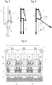
- Fig. 2 the application of the hydraulic actuator 7 in a tamping unit 4 for tamping a sleeper 9, which together with rails 8 forms a track grid supported on a ballast bed 10, is shown.
- the tamping unit 4 is itself connected to the machine frame 3 of a track construction machine and comprises a tamping tool with a pair of swivel arms 5, with which a tamping pick can be inserted by means of the tamping pick holder 6. is connected.
- the tamping tines arranged in two rows with increasing distance from the rail can be pivoted upwards via their tamping tine holders 6 in order to enable the tamping tools to be used in a way that is adapted to the position of the rails 8 at switches.
- Fig. 3 is the tamping unit of Fig. 2 simplified with the links essential for understanding the swiveling process, i.e. the U-shaped swivel arm 5, the tamping pick holder 6 with tamping pick and the hydraulic actuator 7.
- Fig. 4 illustrated by two schematic figures showing the arrangement of Fig. 3 was replaced by a combination of basic geometric-kinematic elements.
- the tamping tine holder 6 and tamping tine are connected to the swivel arm 5 of the tamping unit 4 via a pivot bearing.
- the hydraulic actuator 7 is rotatably connected to the swivel arm 5 of the tamping unit 4 on the one hand and to the tamping tine holder 6 with tamping tine on the other. In an initial position of the piston of the actuator 7, the tamping tine holder 6 and tamping tine are aligned parallel to the swivel arm 5 and can thus participate in the tamping process when the tamping unit 4 is lowered.
- Tamping with one or more tamping picks in the open position serves to achieve a significantly improved tamping result for switches, particularly in the case of a tamping machine whose tamping units 4 cannot be moved horizontally or can only be moved horizontally to a limited extent.
- Fig. 5 represents a variant of the tamping unit 4, in which three identical tamping units 4A, 4B and 4C with individually pivotable tamping pick holders 6 with tamping picks for tamping one sleeper 9 each of a track grid with rails 8 mounted on a ballast bed 10 are arranged to form a combined unit 4 for the synchronous tamping of up to three sleepers 9.
- the hydraulic actuators 7A are used to pivot the tamping picks, the positioning movement is carried out by means of the positioning cylinders 7B and the lowering of one of the units is carried out by means of a hydraulic actuator 7C.
- a variant of the valve arrangement 12a, 12b, 12c and 12d is shown, which allows a hydraulic actuator 7, 7A, 7B, 7C to be controlled according to the method according to the invention.
- the hydraulic actuator 7, 7A, 7B, 7C is a translatory actuator with a piston that divides the cylinder pressure chamber into a piston-side pressure chamber and a rod-side pressure chamber.
- the working connection of the piston-side pressure chamber of the hydraulic actuator 7, 7A, 7B, 7C, designated with A, is connected to the connection T of the hydraulic line system by means of the valve 12a.
- Valve 12c connects A with the connection P of the hydraulic line system.
- valve 12b enables the establishment of a connection between the working port B of the rod-side pressure chamber of the hydraulic actuator 7 and the port T of the hydraulic line system, while valve 12d is arranged to connect the working port B to the port P.
- hydraulic accumulators 13 are located between the pressure chamber connections A, B of the hydraulic actuator 7, 7A, 7B, 7C and the control valves 12a, 12b, 12c and 12d to reduce or avoid pressure fluctuations.
- On-off valves each with two connections and two different switching positions (1) and (2), are used as control valves 12a, 12b, 12c and 12d.
- the passive basic position (1) of such an on-off control valve 12a, 12b, 12c or 12d separates its output from its input. If the on-off control valve 12a, 12b, 12c or 12d is activated against a spring force by an electromagnetic actuating device, in the active position (2) the valve output is connected to the valve input in such a way that the hydraulic medium can act either statically or dynamically both in the direction of the pressure chamber of the hydraulic actuator 7 and in the direction of the connections P and T of the hydraulic line system.
- Fig. 6b shows a 4/3 way seat valve 12e as an alternative to the Fig. 6a shown 2/2 way seat valves 12a-12d. Specifically, the 2/2 way seat valves 12a-12d are replaced by a 4/3 way seat valve 12e.
- coupling means that flexibility is lost when controlling the actuator 7.
- connection P and connection T directly to one another in order to route the hydraulic medium past the actuator (bypass).
- a construction machine 14 is shown on a track, the machine frame of which is connected to a tamping unit 4 and a lifting and straightening unit 15.
- the lifting and straightening unit 15 analogous to the tamping unit 4, there are also various hydraulic actuators 7 for carrying out mostly translational movements.
- Fig. 8 finally shows a switch arrangement consisting of rails 8 and sleepers 9 of a track as a section of a track network in plan view, wherein the switch is set by means of the switch setting device 16.
Landscapes
- Engineering & Computer Science (AREA)
- Physics & Mathematics (AREA)
- Fluid Mechanics (AREA)
- Mechanical Engineering (AREA)
- General Engineering & Computer Science (AREA)
- Architecture (AREA)
- Civil Engineering (AREA)
- Structural Engineering (AREA)
- Fluid-Pressure Circuits (AREA)
Applications Claiming Priority (1)
| Application Number | Priority Date | Filing Date | Title |
|---|---|---|---|
| ATA50507/2023A AT527373A1 (de) | 2023-06-27 | 2023-06-27 | Steuerung eines hydraulischen Aktors |
Publications (3)
| Publication Number | Publication Date |
|---|---|
| EP4484645A1 true EP4484645A1 (fr) | 2025-01-01 |
| EP4484645C0 EP4484645C0 (fr) | 2026-03-11 |
| EP4484645B1 EP4484645B1 (fr) | 2026-03-11 |
Family
ID=91670142
Family Applications (1)
| Application Number | Title | Priority Date | Filing Date |
|---|---|---|---|
| EP24184170.9A Active EP4484645B1 (fr) | 2023-06-27 | 2024-06-25 | Procédé de commande de l'état de fonctionnement d'un actionneur hydraulique d'une unité de bourrage d'un engin de construction de voies ferrées et engin de construction de voies ferrées pour la mise en oeuvre du procédé |
Country Status (2)
| Country | Link |
|---|---|
| EP (1) | EP4484645B1 (fr) |
| AT (2) | AT527373A1 (fr) |
Citations (4)
| Publication number | Priority date | Publication date | Assignee | Title |
|---|---|---|---|---|
| DE10315460A1 (de) * | 2003-03-27 | 2004-10-21 | Steuerungstechnik Staiger Gmbh & Co. Produktions-Vertriebs-Kg | Ventilanordnung für gasförmige und flüssige Medien |
| EP2642132A2 (fr) * | 2012-03-20 | 2013-09-25 | Robert Bosch Gmbh | Agencement de soupape pilote hydraulique et agencement de soupape hydraulique en étant équipé |
| EP2650549A2 (fr) * | 2012-04-12 | 2013-10-16 | Robert Bosch Gmbh | Agencement électro-hydraulique, procédé de commande de l'agencement électro-hydraulique et machine de travail mobile dotée de l'arrangement électro-hydraulique |
| WO2020052879A1 (fr) * | 2018-09-13 | 2020-03-19 | Plasser & Theurer Export Von Bahnbaumaschinen Gmbh | Procédé et dispositif servant à effectuer un bourrage sous les traverses d'une voie ferrée |
Family Cites Families (20)
| Publication number | Priority date | Publication date | Assignee | Title |
|---|---|---|---|---|
| AT294895B (de) | 1965-06-24 | 1971-12-10 | Plasser Bahnbaumasch Franz | Maschine zum Unterstopfen eines Gleises |
| AT339358B (de) | 1974-05-09 | 1977-10-10 | Plasser Bahnbaumasch Franz | Antriebs- und steuereinrichtung fur vibrier- und verstellbare werkzeuge einer gleisbearbeitungsmaschine, insbesondere fahrbare gleisstopfmaschine |
| AT364383B (de) | 1979-02-26 | 1981-10-12 | Plasser Bahnbaumasch Franz | Gleisstopfmaschine mit stopftiefensteuerung |
| DE3709211A1 (de) * | 1987-03-20 | 1988-10-06 | Wabco Westinghouse Steuerung | Einrichtung zur steuerung des kolbens eines arbeitszylinders |
| DE4311191C2 (de) | 1993-04-05 | 1995-02-02 | Deere & Co | Hydrauliksystem zur Versorgung offener oder geschlossener Hydraulikfunktionen |
| DE19813852C2 (de) | 1998-03-27 | 2002-04-11 | Ammann Verdichtung Gmbh | Schwingungserreger, Vibrationsplatte, sowie Verfahren zur mechanischen Schwingungserzeugung |
| US6640685B2 (en) | 2001-02-07 | 2003-11-04 | David M. Hamby | Closed loop electrohydraulic actuator control circuit |
| US6918248B2 (en) * | 2001-04-17 | 2005-07-19 | Caterpillar Inc | Independent metering valve assembly for multiple hydraulic load functions |
| US6598391B2 (en) | 2001-08-28 | 2003-07-29 | Caterpillar Inc | Control for electro-hydraulic valve arrangement |
| DE10322877A1 (de) | 2003-05-21 | 2004-12-30 | Daimlerchrysler Ag | Sitzventil |
| DE102006058913A1 (de) * | 2006-12-13 | 2008-06-19 | Zf Friedrichshafen Ag | Steuerungsvorrichtung für ein Getriebe |
| FR2929664B1 (fr) | 2008-04-08 | 2010-06-04 | Agence Spatiale Europeenne | Procede de commande d'un actionneur hydraulique. |
| DE102012020581A1 (de) | 2012-10-22 | 2014-04-24 | Robert Bosch Gmbh | Hydraulische Schaltung für eine hydraulische Achse und eine hydraulische Achse |
| AT513973B1 (de) | 2013-02-22 | 2014-09-15 | System7 Railsupport Gmbh | Stopfaggregat für eine Gleisstopfmaschine |
| DE102014003084A1 (de) * | 2014-03-01 | 2015-09-03 | Hydac Fluidtechnik Gmbh | Digitalhydraulisches Antriebssystem |
| AT516311B1 (de) | 2014-10-06 | 2016-06-15 | System 7 - Railsupport GmbH | Gleisstopfmaschine zum Verdichten der Schotterbettung eines Gleises |
| AT517843B1 (de) | 2015-11-24 | 2017-05-15 | Plasser & Theurer Export Von Bahnbaumaschinen Gmbh | Verfahren sowie Stopfaggregat zum Unterstopfen eines Gleises |
| DE102018205821A1 (de) | 2018-04-17 | 2019-10-17 | Robert Bosch Gmbh | Vibrationsantreiben mit einem Mehrflächenzylinder |
| AT522456B1 (de) * | 2019-10-08 | 2020-11-15 | Plasser & Theurer Export Von Bahnbaumaschinen Gmbh | Stopfaggregat zum Unterstopfen von Schwellen eines Gleises |
| DE102021116038A1 (de) | 2021-06-21 | 2022-12-22 | RWT Hornegger & Thor GmbH | Elektrohydraulisches steuerventil und dessen anwendung in einem load-sensing-system |
-
2023
- 2023-06-27 AT ATA50507/2023A patent/AT527373A1/de active IP Right Grant
- 2023-06-27 AT ATGM8005/2025U patent/AT18604U1/de unknown
-
2024
- 2024-06-25 EP EP24184170.9A patent/EP4484645B1/fr active Active
Patent Citations (4)
| Publication number | Priority date | Publication date | Assignee | Title |
|---|---|---|---|---|
| DE10315460A1 (de) * | 2003-03-27 | 2004-10-21 | Steuerungstechnik Staiger Gmbh & Co. Produktions-Vertriebs-Kg | Ventilanordnung für gasförmige und flüssige Medien |
| EP2642132A2 (fr) * | 2012-03-20 | 2013-09-25 | Robert Bosch Gmbh | Agencement de soupape pilote hydraulique et agencement de soupape hydraulique en étant équipé |
| EP2650549A2 (fr) * | 2012-04-12 | 2013-10-16 | Robert Bosch Gmbh | Agencement électro-hydraulique, procédé de commande de l'agencement électro-hydraulique et machine de travail mobile dotée de l'arrangement électro-hydraulique |
| WO2020052879A1 (fr) * | 2018-09-13 | 2020-03-19 | Plasser & Theurer Export Von Bahnbaumaschinen Gmbh | Procédé et dispositif servant à effectuer un bourrage sous les traverses d'une voie ferrée |
Also Published As
| Publication number | Publication date |
|---|---|
| AT18604U1 (de) | 2025-12-15 |
| AT527373A1 (de) | 2025-01-15 |
| EP4484645C0 (fr) | 2026-03-11 |
| EP4484645B1 (fr) | 2026-03-11 |
Similar Documents
| Publication | Publication Date | Title |
|---|---|---|
| EP0615583B1 (fr) | Recuperateur d'energie | |
| EP0620371B1 (fr) | Système hydraulique pour alimentation de fonctions hydrauliques ouvertes ou fermées | |
| DE4100988A1 (de) | Hydraulisches antriebssystem | |
| DE102017117335A1 (de) | Betätigungseinheit für ein Prozessventil sowie Prozessventil | |
| DE2140882C3 (de) | Hydraulische Verstelleinrichtung für höhenverstellbare Arbeitsgeräte, insbesondere landwirtschaftliche Bodenbearbeitungsgeräte | |
| DE2130655C3 (de) | Druckmittelnotversorgungseinnchtung für einen hydraulischen Arbeitskreis | |
| DE3245288A1 (de) | Verfahren zur einsparung von energie beim stellen eines ausruestungszylinders an einem hydraulikbagger durch eine hydraulikschaltung | |
| DE102014007439A1 (de) | Pneumatisches Antriebssystem und Verfahren zu seinem Betreiben | |
| EP4484645A1 (fr) | Procédé de commande de l'état de fonctionnement d'un actionneur hydraulique d'une unité de bourrage d'un engin de construction de vois ferrées et agencement pour la mise en oeuvre du procédé | |
| DE3340676A1 (de) | Vorrichtung zum versorgen einer steueranordnung mit steuerdruckmittel | |
| DE69029904T2 (de) | Hydraulische schaltungsanordnung | |
| DE2937764A1 (de) | Hydraulisches system | |
| DE19681624B4 (de) | Druckmittelsystem, insbesondere zum Anwenden und Steuern einer Hochhebeauslegereinheit, in Verbindung mit einer Arbeitsmaschine | |
| EP2466154B1 (fr) | Dispositif de commande hydroélectrique | |
| EP0238782B1 (fr) | Unité de vanne à 5/3 voies | |
| DE102008008102A1 (de) | Verfahren und Vorrichtung zur Druckmittelversorgung von zumindest drei hydraulischen Verbrauchern | |
| DE19548943B4 (de) | Ventilanordnung | |
| DE10247967B3 (de) | Mehrwegeventil mit Fluidsparmaßnahmen | |
| EP0735275B1 (fr) | Dispositif à crans | |
| DE10148962C1 (de) | Steuervorrichtung | |
| DE2753507B2 (de) | Hydraulische Steuerung für einen Rundschalttisch | |
| EP1419910B1 (fr) | Suspension hydropneumatique | |
| DE2800814A1 (de) | Hydraulische steuereinrichtung | |
| DE102004048642A1 (de) | Hydraulische Steueranordnung | |
| DE102011013187B4 (de) | Abluftnutzschaltung |
Legal Events
| Date | Code | Title | Description |
|---|---|---|---|
| PUAI | Public reference made under article 153(3) epc to a published international application that has entered the european phase |
Free format text: ORIGINAL CODE: 0009012 |
|
| STAA | Information on the status of an ep patent application or granted ep patent |
Free format text: STATUS: THE APPLICATION HAS BEEN PUBLISHED |
|
| AK | Designated contracting states |
Kind code of ref document: A1 Designated state(s): AL AT BE BG CH CY CZ DE DK EE ES FI FR GB GR HR HU IE IS IT LI LT LU LV MC ME MK MT NL NO PL PT RO RS SE SI SK SM TR |
|
| STAA | Information on the status of an ep patent application or granted ep patent |
Free format text: STATUS: REQUEST FOR EXAMINATION WAS MADE |
|
| 17P | Request for examination filed |
Effective date: 20250701 |
|
| GRAP | Despatch of communication of intention to grant a patent |
Free format text: ORIGINAL CODE: EPIDOSNIGR1 |
|
| STAA | Information on the status of an ep patent application or granted ep patent |
Free format text: STATUS: GRANT OF PATENT IS INTENDED |
|
| TPAC | Observations filed by third parties |
Free format text: ORIGINAL CODE: EPIDOSNTIPA |
|
| RIC1 | Information provided on ipc code assigned before grant |
Ipc: E01B 27/16 20060101AFI20250925BHEP Ipc: F15B 11/00 20060101ALI20250925BHEP Ipc: F15B 11/024 20060101ALI20250925BHEP Ipc: E02F 9/22 20060101ALI20250925BHEP |
|
| INTG | Intention to grant announced |
Effective date: 20251008 |
|
| GRAS | Grant fee paid |
Free format text: ORIGINAL CODE: EPIDOSNIGR3 |
|
| GRAA | (expected) grant |
Free format text: ORIGINAL CODE: 0009210 |
|
| STAA | Information on the status of an ep patent application or granted ep patent |
Free format text: STATUS: THE PATENT HAS BEEN GRANTED |
|
| AK | Designated contracting states |
Kind code of ref document: B1 Designated state(s): AL AT BE BG CH CY CZ DE DK EE ES FI FR GB GR HR HU IE IS IT LI LT LU LV MC ME MK MT NL NO PL PT RO RS SE SI SK SM TR |
|
| REG | Reference to a national code |
Ref country code: CH Ref legal event code: F10 Free format text: ST27 STATUS EVENT CODE: U-0-0-F10-F00 (AS PROVIDED BY THE NATIONAL OFFICE) Effective date: 20260311 Ref country code: GB Ref legal event code: FG4D Free format text: NOT ENGLISH |
|
| REG | Reference to a national code |
Ref country code: DE Ref legal event code: R026 Ref document number: 502024000850 Country of ref document: DE |
|
| PLBI | Opposition filed |
Free format text: ORIGINAL CODE: 0009260 |
|
| REG | Reference to a national code |
Ref country code: CH Ref legal event code: L11 Free format text: ST27 STATUS EVENT CODE: U-0-0-L10-L11 (AS PROVIDED BY THE NATIONAL OFFICE) Effective date: 20260325 |
|
| REG | Reference to a national code |
Ref country code: DE Ref legal event code: R096 Ref document number: 502024000850 Country of ref document: DE |
|
| REG | Reference to a national code |
Ref country code: IE Ref legal event code: FG4D Free format text: LANGUAGE OF EP DOCUMENT: GERMAN |
|
| 26 | Opposition filed |
Opponent name: HP3 REAL GMBH Effective date: 20260313 |
|
| U01 | Request for unitary effect filed |
Effective date: 20260319 |
|
| U07 | Unitary effect registered |
Designated state(s): AT BE BG DE DK EE FI FR IT LT LU LV MT NL PT RO SE SI Effective date: 20260326 |