EP4484684A2 - Gâche électrique - Google Patents
Gâche électrique Download PDFInfo
- Publication number
- EP4484684A2 EP4484684A2 EP24179682.0A EP24179682A EP4484684A2 EP 4484684 A2 EP4484684 A2 EP 4484684A2 EP 24179682 A EP24179682 A EP 24179682A EP 4484684 A2 EP4484684 A2 EP 4484684A2
- Authority
- EP
- European Patent Office
- Prior art keywords
- door opener
- terminal block
- circuit board
- housing
- block
- Prior art date
- Legal status (The legal status is an assumption and is not a legal conclusion. Google has not performed a legal analysis and makes no representation as to the accuracy of the status listed.)
- Pending
Links
Images





Classifications
-
- E—FIXED CONSTRUCTIONS
- E05—LOCKS; KEYS; WINDOW OR DOOR FITTINGS; SAFES
- E05B—LOCKS; ACCESSORIES THEREFOR; HANDCUFFS
- E05B47/00—Operating or controlling locks or other fastening devices by electric or magnetic means
- E05B47/0046—Electric or magnetic means in the striker or on the frame; Operating or controlling the striker plate
- E05B47/0047—Striker rotating about an axis parallel to the wing edge
-
- H—ELECTRICITY
- H01—ELECTRIC ELEMENTS
- H01R—ELECTRICALLY-CONDUCTIVE CONNECTIONS; STRUCTURAL ASSOCIATIONS OF A PLURALITY OF MUTUALLY-INSULATED ELECTRICAL CONNECTING ELEMENTS; COUPLING DEVICES; CURRENT COLLECTORS
- H01R9/00—Structural associations of a plurality of mutually-insulated electrical connecting elements, e.g. terminal strips or terminal blocks; Terminals or binding posts mounted upon a base or in a case; Bases therefor
- H01R9/03—Connectors arranged to contact a plurality of the conductors of a multiconductor cable, e.g. tapping connections
- H01R9/031—Connectors arranged to contact a plurality of the conductors of a multiconductor cable, e.g. tapping connections for multiphase cables, e.g. with contact members penetrating insulation of a plurality of conductors
-
- H—ELECTRICITY
- H01—ELECTRIC ELEMENTS
- H01R—ELECTRICALLY-CONDUCTIVE CONNECTIONS; STRUCTURAL ASSOCIATIONS OF A PLURALITY OF MUTUALLY-INSULATED ELECTRICAL CONNECTING ELEMENTS; COUPLING DEVICES; CURRENT COLLECTORS
- H01R9/00—Structural associations of a plurality of mutually-insulated electrical connecting elements, e.g. terminal strips or terminal blocks; Terminals or binding posts mounted upon a base or in a case; Bases therefor
- H01R9/22—Bases, e.g. strip, block, panel
- H01R9/24—Terminal blocks
- H01R9/2458—Electrical interconnections between terminal blocks
- H01R9/2466—Electrical interconnections between terminal blocks using a planar conductive structure, e.g. printed circuit board
Definitions
- the invention relates to an electric door opener.
- connection block on the well-known door openers is usually designed with clamping screws for connecting the connection cables and requires screwing work with a screwdriver tool.
- the electrical connections in the door opener on the well-known door openers are made via wiring.
- the invention is based on the object of improving the electrical connections within the door opener in connection with the connection block in order to obtain advantages in the manufacture and/or assembly and/or handling of the door opener.
- the anchor, the change and the door opener latch are preferably connected in a line.
- the electrically switchable locking device can be electrically switched in a locking switching position and a release switching position in such a way that in the locking switching position it switches the door opener latch into a locking position and in the release switching position it switches the door opener latch into a release position.
- Preferred embodiments can provide that the first terminal block and the circuit board are immobile with the rest of the door opener housing and the second terminal block is movable relative to the door opener housing or vice versa: that the second terminal block is immobile with the rest of the door opener housing and the first terminal block and the circuit board are movable relative to the door opener housing.
- Preferred embodiments can provide that the second terminal block and/or a part of the second terminal block is arranged and/or guided in a receiving space in the interior of the first terminal block, preferably guided linearly, and/or is arranged and/or guided in a receiving space between the first terminal block and the circuit board, preferably guided linearly.
- the second terminal block has a receiving and/or supporting device acting as a stamp and/or an anvil for the at least one connecting cable.
- Preferred embodiments can provide that by relative movement between the first terminal block and the second terminal block, the second terminal block and/or a part of the second terminal block in the receiving space can be selectively adjusted to two positions, namely a first position and a second position, wherein the first position is an assembly position in which the connecting cable arranged in the receiving and/or support device is arranged out of contact with the insulation displacement terminal, and wherein the second position is a preferably latchable contact position in which the connecting cable arranged in the receiving and/or support device is arranged in contact with the insulation displacement terminal.
- Preferred embodiments can provide that the first terminal block and/or the second terminal block has at least one inlet opening for the connection cable, wherein the inlet opening is preferably designed as an elongated hole with an extension direction along the direction of the relative movement between the second terminal block and the first terminal block.
- the second terminal block is designed at one end as an actuating end, preferably with a handle device, e.g. as an engagement recess, and has the receiving and/or supporting device for the connecting cable at its free end.
- the first clamping block forms an outer wall, preferably a front side of the door opener housing, wherein the vertical extension of the outer wall formed by the first clamping block, preferably front wall, is shorter than the vertical extension of an adjacent outer wall, preferably front wall or side wall of the door opener housing, forming a gap between the actuating end of the second clamping block and a preferably parallel edge of the door opener housing, preferably the bottom edge or the ceiling edge of the door opener housing, wherein during the relative movement between the second clamping block and the first clamping block, the actuating end of the second clamping block can be adjusted within the gap, preferably in a lockable manner.
- Preferred embodiments can provide that the actuating end of the second terminal block is arranged in the region of the gap in the second position and/or contact position of the second terminal block, forming a residual gap between the actuating end of the second terminal block and the edge of the door opener housing, preferably the bottom edge or the ceiling edge of the door opener housing.
- Preferred embodiments may provide that the actuating end of the second clamping block is arranged in the first position and/or mounting position in the gap such that the actuating end of the second terminal block is flush with the edge of the door opener housing, preferably the lower edge or the upper edge of the door opener housing, or protrudes beyond this edge.
- Preferred embodiments may provide that the first terminal block and the circuit board are connected via a plurality of pins which are arranged perpendicular to the planar extension of the first terminal block and/or the circuit board.
- Preferred embodiments can provide that at least one of the pins is firmly connected to the first terminal block and is inserted and/or fixed with its free end into a receptacle, preferably a blind hole or through hole in the circuit board, or vice versa, that at least one of the pins is firmly connected to the circuit board and is inserted and/or fixed with its free end into a receptacle, preferably a blind hole or through hole in the first terminal block.
- Preferred embodiments may provide that pins are designed as spacers which form a gap between the first terminal block and the circuit board for receiving and/or guiding the relative movement between the first terminal block and the second terminal block.
- the first terminal block has at least one through-hole and the circuit board has at least one contact pad in alignment with the at least one through-hole, which is connected to the conductor track or tracks of the circuit board, wherein the at least one through-hole is for the passage of at least one contact pin and the contact pad is for contacting the free end of the at least one contact pin extending through it for the purpose of supplying current to the conductor track or tracks of the printed circuit board.
- the at least one insulation displacement terminal of the circuit board protrudes and/or protrudes from the plate-shaped body of the circuit board made of plastic or from the plate-shaped body of the circuit board provided with a plastic coating and forms at least one insulation displacement contact with at least one of the conductor tracks of the circuit board during the relative movement between the second terminal block and the first terminal block and/or the circuit board, preferably for connecting the at least one connection cable, and that it is preferably provided that the circuit board has at least one further area connected to at least one of the conductor tracks, preferably protruding and/or protruding from the body of the circuit board made of plastic and/or from the body of the circuit board provided with a plastic coating, forming a non-cutting contact, preferably a pure plug connection, preferably for connecting an electrical or electronic component, e.g. an SMD diode.
- the first clamping block is made of plastic, preferably glass fiber reinforced plastic, preferably manufactured as an injection molded part.
- the second clamping block is made of plastic, preferably glass fiber reinforced plastic, preferably manufactured as an injection molded part.
- the circuit board has a coating made of plastic or has a body made of plastic, preferably glass fiber reinforced plastic, which is preferably designed as a plastic injection molded part and/or as a circuit board, preferably with a wall thickness in the range of 1.5 mm.
- Preferred embodiments can provide that the conductor tracks of the circuit board are designed as metallic conductors, preferably formed by etching processes, and/or are formed from separately manufactured metallic parts, preferably stamped parts.
- Preferred embodiments can provide that the conductor tracks in the circuit board are arranged on an outer side and/or in the interior of the circuit board, preferably in a form-fitting and/or integrated manner, preferably by inserting or casting the conductor tracks or by subsequently applying or inserting them into grooves and fixing them by gluing or soldering.
- the armature 4, the change 5 and the door opener latch 1 are connected in a line one behind the other.
- the electrically switchable locking device 3 can be electrically switched in a locking switching position and a release switching position such that in the locking switching position it switches the door opener latch 1 into a locking position and in the release switching position it switches the door opener latch 1 into a release position.
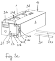
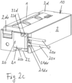
- the door opener 10 shown in the figures has a connection block for the electrical connection via connection cable 20x, which is designed as an assembly 20.
- This assembly comprises a first terminal block 21 as a housing-fixed terminal block, a second terminal block 22 as a movable terminal block and a circuit board 23 which is connected to the first terminal block in a housing-fixed manner. As will be described in more detail below.
- the electric door opener 10 should - as is the rule in practice - be installed on a stationary frame of a door and is associated with a lock mounted on the door leaf.
- the reverse installation is also possible in principle, where the electric door opener is mounted on the door leaf and the associated lock is mounted on the stationary door frame.
- the door can be - as is often the case in practice - a revolving door with a revolving leaf.
- the door opener 10 interacts with a lock latch of the associated lock via its door opener latch 1. This interaction is as follows: When the door is in the closed position, the lock latch engages behind the door opener latch 1. When the electrically switchable locking device 3 is in the locked position, the door opener latch 1 is in the locked position. In its closed position, the door is blocked against movement of the door in the opening direction by the door opener latch 1 which is in the locked position.
- the door opener latch 1 which is locked in the locked position, forms a fixed stop for the lock latch against movement of the door in the opening direction.
- the lock latch cannot pass the locked door opener latch 1.
- the electrically switchable locking position 3 When the electrically switchable locking position 3 is switched to its release position, it sets the door opener latch to the release position. With the door opener latch in this position, the door can then be moved from the closed position in the opening direction. The lock latch passes the door opener latch 1, which is no longer locked. When passing, the door opener latch 1 is pushed over against the force of its return spring.
- the lock latch can be designed as a spring-loaded, so-called shooting latch. It has a slope on the side facing the closing direction, which interacts with the door opener latch when the door is closed, in such a way that the lock latch can pass the door opener latch when the door is moved into the closed position while it is in the closed position.
- the lock latch is overpressed, ie retracted into the lock against its return spring.
- connection device designed as module 20:
- the assembly 20 is arranged on a front side of the door opener housing 2. It forms part of the front side 2s of the door opener housing.
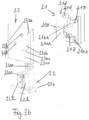
- the circuit board 23 has two conductor tracks 23y, each of the conductor tracks 23y being electrically connected to an insulation displacement terminal 23sk assigned to it.
- the insulation displacement terminals 23sk are firmly connected to the circuit board 23 and protrude beyond the extension plane of the circuit board.
- the circuit board is connected to the coil of the electrically switchable locking device 3 via coil wires 3x.
- the coil wires 3x are connected to the assigned conductor tracks 23y via corresponding coil connections 23ax.
- first terminal block 21 which is mounted in the door opener housing 2, preferably in one or more fastening grooves and/or catches:
- This first terminal block 21 is mounted in a fixed manner to the housing.
- the circuit board 23 is connected to the first terminal block 21 in a fixed manner via pins 21z.
- the first terminal block 21 forms a Part of the door opener housing 2, which in the present case has a cuboid-shaped basic configuration.
- the circuit board 23 is - as already mentioned - part of an end wall 2s of the door opener housing.
- the fastening of the first terminal block 21 in the housing is realized on one side in connection with the housing rear wall adjacent to the terminal block 21 and on the other side in connection with the front housing block adjacent to the terminal block 21.
- This second terminal block 22 acts as a movable stamp that interacts with the insulation displacement contacts 23sk of the circuit board 23 to create and/or release the insulation displacement contacts between the connection cables 20x and the insulation displacement contacts 23sk. This interaction takes place when the movable terminal block 22 is moved upwards in the illustration in the figures via its actuating end 22b, which is formed at the bottom end and has an engagement. This is a sliding movement in which the two stamp-like holders 22h of the terminal block 22 are moved in a linearly guided manner in complementary receiving spaces, which are formed inside the fixed terminal block 21 as shaft-like receiving and guide spaces.
- the contact position is maintained as an insulation displacement contact between the connecting cables 20x and the insulation displacement terminals 23sk.
- receiving and/or support devices 22ax are formed, in which the connecting cables 20x are inserted, so that when the terminal block 22 is pushed up, the connecting cables held in the holders 22h are taken along and in the upper position come into cutting contact with the insulation displacement terminals 23sk.
- FIG. 2a the movable clamping block 22 is in its lower position, ie a position 1 as the assembly position.
- the connecting cables 20x can be inserted through the inlet openings 21 dx in the first fixed terminal block 21.
- the inlet openings are designed as through holes in such a way that the connecting cables can be inserted into the respective receiving and guide space and are thereby inserted into the receiving and/or support device 22ax at the upper end of the stamp-like holders 22h of the movable terminal block 22.
- This assembly position with inserted connecting cables 20x is in Fig. 2b shown.
- Fig. 2c the contact position, ie the active position, is shown in which the insulation displacement connection between the insulation displacement terminals 22sk and the connecting cables 20x is made and maintained.
- the terminal block 22 is pushed upwards, namely into its upper position in which the insulation displacement connection is formed.
- the terminal block 22 can be locked in this position, e.g. by a latch.
Landscapes
- Lock And Its Accessories (AREA)
- Patch Boards (AREA)
Applications Claiming Priority (1)
| Application Number | Priority Date | Filing Date | Title |
|---|---|---|---|
| DE102023115017.0A DE102023115017A1 (de) | 2023-06-07 | 2023-06-07 | Elektrischer Türöffner |
Publications (2)
| Publication Number | Publication Date |
|---|---|
| EP4484684A2 true EP4484684A2 (fr) | 2025-01-01 |
| EP4484684A3 EP4484684A3 (fr) | 2025-03-12 |
Family
ID=91375813
Family Applications (1)
| Application Number | Title | Priority Date | Filing Date |
|---|---|---|---|
| EP24179682.0A Pending EP4484684A3 (fr) | 2023-06-07 | 2024-06-03 | Gâche électrique |
Country Status (2)
| Country | Link |
|---|---|
| EP (1) | EP4484684A3 (fr) |
| DE (1) | DE102023115017A1 (fr) |
Family Cites Families (4)
| Publication number | Priority date | Publication date | Assignee | Title |
|---|---|---|---|---|
| ES1058768Y (es) * | 2004-10-28 | 2005-05-16 | Nadal Badal S A | Conector modular. |
| DE102010018176A1 (de) * | 2010-04-22 | 2011-10-27 | Dorma Gmbh + Co. Kg | Türöffner |
| DE102020131199A1 (de) * | 2020-11-25 | 2022-05-25 | Brose Fahrzeugteile Se & Co. Kommanditgesellschaft, Bamberg | Baugruppe für ein Fahrzeug mit einer einen biegesteifen Draht aufweisenden Leitungseinheit und Herstellungsverfahren |
| DE102021129577A1 (de) * | 2021-11-12 | 2023-05-17 | WAGO Verwaltungsgesellschaft mit beschränkter Haftung | Leiteranschlussklemme |
-
2023
- 2023-06-07 DE DE102023115017.0A patent/DE102023115017A1/de active Pending
-
2024
- 2024-06-03 EP EP24179682.0A patent/EP4484684A3/fr active Pending
Also Published As
| Publication number | Publication date |
|---|---|
| DE102023115017A1 (de) | 2024-12-12 |
| EP4484684A3 (fr) | 2025-03-12 |
Similar Documents
| Publication | Publication Date | Title |
|---|---|---|
| DE102019127464B3 (de) | Anschlusseinrichtung zum Anschließen einer elektrischen Leitung | |
| EP0920714B2 (fr) | Appareil electrique ou electronique | |
| EP1816706B1 (fr) | Borne de connexion électrique | |
| EP3743961B1 (fr) | Système modulaire permettant de fabriquer un appareil électrique et dispositif de serrage | |
| DE202022002389U1 (de) | Direktsteckfederkraftmodul | |
| DE102013114519A1 (de) | Türöffner mit elektrischem Anschlussblock | |
| DE10103187B4 (de) | Elektrische Klemme | |
| EP3813198B1 (fr) | Dispositif de raccordement permettant de raccorder une conduite électrique | |
| EP3698440B1 (fr) | Pince de fixation | |
| DE10205470C1 (de) | Anschlusskontakt | |
| DE102006042408A1 (de) | Steckvorrichtung zum Stecken auf eine elektrische Schaltvorrichtung | |
| DE102008014180B4 (de) | Trennklemme, insbesondere Neutralleiter-Trennklemme | |
| EP4484684A2 (fr) | Gâche électrique | |
| WO2021148423A1 (fr) | Ensemble d'un dispositif électronique comportant un boîtier électronique et une bande de base | |
| DE102012203554A1 (de) | Sammelschienenabgreifklemme | |
| EP1547454B1 (fr) | Appareil electronique pourvu d'un support de circuit a logement flottant | |
| WO2004023606A1 (fr) | Borne de traversee | |
| DE10216574B4 (de) | Wandeinbaugehäuse für elektrische Bauteile | |
| DE19817433C2 (de) | Elektrische Anschlußbaueinheit | |
| DE19846196A1 (de) | Verbinder für eine Fahrzeug-Batterie | |
| BE1032147B1 (de) | Sensor-Aktor-Verteiler | |
| DE102023109567A1 (de) | Modulares elektrisches Verbindungssystem für einen Schaltschrank | |
| DE102017105413B4 (de) | Elektrisches Reiheneinbaugerät und Anordnung von elektrischen Reiheneinbaugeräten | |
| DE102024127861A1 (de) | Anschlussklemme zum Anschließen einer elektrischen Leitung | |
| DE102023132109A1 (de) | Sensor-Aktor-Verteiler |
Legal Events
| Date | Code | Title | Description |
|---|---|---|---|
| PUAI | Public reference made under article 153(3) epc to a published international application that has entered the european phase |
Free format text: ORIGINAL CODE: 0009012 |
|
| STAA | Information on the status of an ep patent application or granted ep patent |
Free format text: STATUS: THE APPLICATION HAS BEEN PUBLISHED |
|
| AK | Designated contracting states |
Kind code of ref document: A2 Designated state(s): AL AT BE BG CH CY CZ DE DK EE ES FI FR GB GR HR HU IE IS IT LI LT LU LV MC ME MK MT NL NO PL PT RO RS SE SI SK SM TR |
|
| PUAL | Search report despatched |
Free format text: ORIGINAL CODE: 0009013 |
|
| STAA | Information on the status of an ep patent application or granted ep patent |
Free format text: STATUS: REQUEST FOR EXAMINATION WAS MADE |
|
| AK | Designated contracting states |
Kind code of ref document: A3 Designated state(s): AL AT BE BG CH CY CZ DE DK EE ES FI FR GB GR HR HU IE IS IT LI LT LU LV MC ME MK MT NL NO PL PT RO RS SE SI SK SM TR |
|
| RIC1 | Information provided on ipc code assigned before grant |
Ipc: H01R 4/24 20180101ALI20250205BHEP Ipc: E05B 47/00 20060101AFI20250205BHEP |
|
| 17P | Request for examination filed |
Effective date: 20250211 |
|
| GRAP | Despatch of communication of intention to grant a patent |
Free format text: ORIGINAL CODE: EPIDOSNIGR1 |
|
| STAA | Information on the status of an ep patent application or granted ep patent |
Free format text: STATUS: GRANT OF PATENT IS INTENDED |
|
| RIC1 | Information provided on ipc code assigned before grant |
Ipc: E05B 47/00 20060101AFI20260227BHEP Ipc: H01R 4/24 20180101ALI20260227BHEP |
|
| INTG | Intention to grant announced |
Effective date: 20260317 |