EP4484721A1 - Détection du détachement d'un conduit d'un séparateur de gaz de carter de vilebrequin - Google Patents
Détection du détachement d'un conduit d'un séparateur de gaz de carter de vilebrequin Download PDFInfo
- Publication number
- EP4484721A1 EP4484721A1 EP23181423.7A EP23181423A EP4484721A1 EP 4484721 A1 EP4484721 A1 EP 4484721A1 EP 23181423 A EP23181423 A EP 23181423A EP 4484721 A1 EP4484721 A1 EP 4484721A1
- Authority
- EP
- European Patent Office
- Prior art keywords
- load
- gas separator
- threshold value
- measured
- crankcase
- Prior art date
- Legal status (The legal status is an assumption and is not a legal conclusion. Google has not performed a legal analysis and makes no representation as to the accuracy of the status listed.)
- Pending
Links
Images



Classifications
-
- F—MECHANICAL ENGINEERING; LIGHTING; HEATING; WEAPONS; BLASTING
- F01—MACHINES OR ENGINES IN GENERAL; ENGINE PLANTS IN GENERAL; STEAM ENGINES
- F01M—LUBRICATING OF MACHINES OR ENGINES IN GENERAL; LUBRICATING INTERNAL COMBUSTION ENGINES; CRANKCASE VENTILATING
- F01M11/00—Component parts, details or accessories, not provided for in, or of interest apart from, groups F01M1/00 - F01M9/00
- F01M11/10—Indicating devices; Other safety devices
-
- F—MECHANICAL ENGINEERING; LIGHTING; HEATING; WEAPONS; BLASTING
- F01—MACHINES OR ENGINES IN GENERAL; ENGINE PLANTS IN GENERAL; STEAM ENGINES
- F01M—LUBRICATING OF MACHINES OR ENGINES IN GENERAL; LUBRICATING INTERNAL COMBUSTION ENGINES; CRANKCASE VENTILATING
- F01M13/00—Crankcase ventilating or breathing
- F01M13/02—Crankcase ventilating or breathing by means of additional source of positive or negative pressure
- F01M13/021—Crankcase ventilating or breathing by means of additional source of positive or negative pressure of negative pressure
-
- F—MECHANICAL ENGINEERING; LIGHTING; HEATING; WEAPONS; BLASTING
- F01—MACHINES OR ENGINES IN GENERAL; ENGINE PLANTS IN GENERAL; STEAM ENGINES
- F01M—LUBRICATING OF MACHINES OR ENGINES IN GENERAL; LUBRICATING INTERNAL COMBUSTION ENGINES; CRANKCASE VENTILATING
- F01M13/00—Crankcase ventilating or breathing
- F01M13/04—Crankcase ventilating or breathing having means for purifying air before leaving crankcase, e.g. removing oil
-
- F—MECHANICAL ENGINEERING; LIGHTING; HEATING; WEAPONS; BLASTING
- F01—MACHINES OR ENGINES IN GENERAL; ENGINE PLANTS IN GENERAL; STEAM ENGINES
- F01M—LUBRICATING OF MACHINES OR ENGINES IN GENERAL; LUBRICATING INTERNAL COMBUSTION ENGINES; CRANKCASE VENTILATING
- F01M13/00—Crankcase ventilating or breathing
- F01M13/02—Crankcase ventilating or breathing by means of additional source of positive or negative pressure
- F01M13/021—Crankcase ventilating or breathing by means of additional source of positive or negative pressure of negative pressure
- F01M2013/026—Crankcase ventilating or breathing by means of additional source of positive or negative pressure of negative pressure with pumps sucking air or blow-by gases from the crankcase
-
- F—MECHANICAL ENGINEERING; LIGHTING; HEATING; WEAPONS; BLASTING
- F01—MACHINES OR ENGINES IN GENERAL; ENGINE PLANTS IN GENERAL; STEAM ENGINES
- F01M—LUBRICATING OF MACHINES OR ENGINES IN GENERAL; LUBRICATING INTERNAL COMBUSTION ENGINES; CRANKCASE VENTILATING
- F01M13/00—Crankcase ventilating or breathing
- F01M13/04—Crankcase ventilating or breathing having means for purifying air before leaving crankcase, e.g. removing oil
- F01M2013/0422—Separating oil and gas with a centrifuge device
-
- F—MECHANICAL ENGINEERING; LIGHTING; HEATING; WEAPONS; BLASTING
- F01—MACHINES OR ENGINES IN GENERAL; ENGINE PLANTS IN GENERAL; STEAM ENGINES
- F01M—LUBRICATING OF MACHINES OR ENGINES IN GENERAL; LUBRICATING INTERNAL COMBUSTION ENGINES; CRANKCASE VENTILATING
- F01M2250/00—Measuring
- F01M2250/62—Load
Definitions
- the present disclosure relates to a method of a control unit of detecting detachment of a conduit arranged to be attached to an inlet of a crankcase gas separator in fluid connection with a crankcase of a combustion engine, and a control device performing the method.
- combustion gases may leak from the combustion chamber and end up inside the crankcase.
- crankcase gas This leaking causes pressure to build up in the crankcase over time and the gases can condense and mix with the oil vapor that is present in the crankcase, which causes sludge to form or the oil to degrade. This is undesired both from an environmental and engine performance perspective. For certain types of combustion engines, legislation even requires crankcase gas to be disposed of in an environmentally friendly manner.
- crankcase gas separator a device known as a crankcase gas separator.
- an issue with known separators is that a hose or conduit from the crankcase supplying the crankcase gas to the separator easily can be disconnected from the separator, in which case ventilation will fail.
- One objective is to solve, or at least mitigate, this problem in the art and thus to provide a method of detecting any detachment of a conduit from an inlet of a crankcase gas separator.
- a method of a control unit of detecting detachment of a gas flow conduit arranged to be attached to a crankcase gas separator in fluid connection with a crankcase of a combustion engine comprises measuring a load of a motor operating the crankcase gas separator, determining whether at least one of the measured load exceeds an upper load threshold value and the measured load is below a lower load threshold value, and if so detecting that the gas flow conduit is indicated to have been detached from the crankcase gas separator.
- a control unit configured to detect detachment of a gas flow conduit arranged to be attached to a crankcase gas separator in fluid connection with a crankcase of a combustion engine.
- the control unit is configured to measure a load of a motor operating the crankcase gas separator, determine whether at least one of the measured load exceeds an upper load threshold value and the measured load is below a lower load threshold value, and if so to detect that the gas flow conduit is indicated to have been detached from the crankcase gas separator.
- control device of the second aspect being configured to perform the method of the first aspect and its various embodiments, it may be detected by measuring a load of a motor operating the crankcase gas separator whether or not a gas flow conduit, such as the gas flow conduit at the inlet of the separator has been detached.
- the gas flow conduit is an inlet conduit arranged to be attached to an inlet of the crankcase gas separator or an outlet conduit arranged to be attached to an outlet of the crankcase gas separator.
- the measured load exceeding the upper load threshold value indicates that the inlet conduit has been detached from the crankcase gas separator with the inlet being open or that the outlet conduit has been detached from the crankcase gas separator with the outlet being open.
- the measured load being below the lower load threshold value indicates that the inlet conduit has been detached from the crankcase gas separator with the inlet being plugged or that the outlet conduit has been detached from the crankcase gas separator with the outlet being plugged.
- the determining of the measured load exceeding an upper threshold load value comprises determining that the measured load increases from a first lower level to a second higher level exceeding the upper load threshold value within a specified time period.
- the determining of the measured load exceeding an upper threshold load value comprises determining that the measured load exceeds the upper threshold load value for a specified number of sequential load measurements.
- the determining that the measured load exceeds the upper threshold load value for a specified number of sequential load measurements comprises determining that the measured load does not exceed a yet higher threshold load value during the specified number of sequential load measurements.
- the determining of the measured load being below a lower threshold load value comprises determining that the measured load is below the lower load threshold value for the specified number of sequential load measurements.
- the determining that the measured load is below the lower threshold load value for a specified number of sequential load measurements comprises determining that the measured load does not fall below a yet lower load threshold value during the specified number of sequential load measurements.
- an operational mode of the combustion engine is selected where an expected load of the motor will not exceed the upper load threshold value.
- an operational mode of the combustion engine is selected where an expected load of the motor will not fall below the lower load threshold value.
- the measuring of a load comprises measuring a load of a motor operating the crankcase gas separator both at a first operational mode of the combustion engine and at a second operational mode of the combustion engine, and the determining comprises determining, for both operational modes of the combustion engine, whether the measured load exceeds an upper load threshold value or the measured load is below a lower load threshold value and if so, detecting that the gas flow conduit is indicated to have been detached from the crankcase gas separator.
- the method further comprises providing an alert that the gas flow conduit is detected to have been detached from the crankcase gas separator.
- the motor is configured to cause a rotating member of the crankcase gas separator to rotate in order to cause the crankcase gas to flow through the crankcase gas separator to be separated into a gaseous phase exiting the crankcase gas separator via a gas outlet and into a liquid phase exiting the crankcase gas separator via a liquid outlet.
- the load of the motor operating the crankcase gas separator is measured by either measuring power or current consumption of the motor.
- a computer program comprising computer-executable instructions for causing a control unit of the second aspect to perform the method of the fist aspect when the computer-executable instructions are executed on a processing unit included in the control unit.
- a computer program product comprising a non-transitory computer readable medium, the computer readable medium having the computer program according to the third aspect embodied thereon.
- FIG 1 schematically illustrates an internal combustion engine (ICE) 40 according to an example in which embodiments may be implemented .
- the ICE 40 comprises a crankcase 41 and a centrifugal separator 1 for cleaning of crankcase gas, which separator 1 is controlled by control unit 28.
- the ICE 40 will in practice comprises far more components than those illustrated for brevity in Figure 1 .
- the separator 1 will be described in detail with reference to Figure 2 below.
- the ICE 30 may be a compression ignition or spark ignition four-stroke or two-stroke ICE.
- the ICE 30 comprises at least one piston arranged in a cylinder bore of the ICE 30.
- a connecting rod connects the piston with a crankshaft 42 inside the crankcase 41.
- the piston reciprocates in the cylinder bore and drives the crankshaft 42.
- crankcase gas may comprise, oil, other liquid hydrocarbons, soot, and other solid combustion residues.
- control unit 28 By means of control unit 28, the rotational speed and thereby the cleaning efficiency of the centrifugal separator 1 may be controlled in a suitable way so that a required cleaning of the supplied gas is obtained, as will be discussed in more detail with reference to Figure 2 below.
- a conduit 18 fluidly connects an interior of the crankcase 41 with the centrifugal separator 1.
- the crankcase gas is separated into a gaseous phase and a liquid phase.
- the separated liquid phase is lead out of the centrifugal separator via a liquid outlet 29, back to the crankcase 41.
- the gaseous phase is lead out of the centrifugal separator 1, via a gas outlet 30 and an outlet conduit 35, to a fresh gas inlet of the ICE 40.
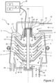
- FIG 2 shows a section of a prior art centrifugal crankcase gas separator 1 for which embodiments may be implemented .
- the separator 1 comprises a stationary casing 2, which is configured to be mounted to a combustion engine (such as engine XX illustrated in Figure 1 ), such as a diesel engine.
- the separator 1 is mounted at a suitable position, for instance on top or at a side of the combustion engine.
- the separator 1 also is suitable for cleaning gases from other sources than combustion engines, for instance machine tools which frequently contains large amounts of liquid impurities in the form of oil droplets or oil mist.
- the stationary casing 2 encloses a separation space 3 through which a gas flow is permitted.
- the stationary casing 2 comprises, or is formed by, a surrounding side wall 4, a first end wall 5 and a second end wall 6.
- the separator 1 comprises a rotating member 7, which is arranged to rotate around an axis X of rotation. It should be noted that the stationary casing 2 is stationary in relation to the rotating member 7, and preferably in relation to the combustion engine to which it may be mounted.
- the rotating member 7 comprises a spindle 8 and a stack of separation discs 9 attached to the spindle 8. All the separation discs of the stack 9 are provided between a first end plate 10 and a second end plate 11.
- the spindle 8, and thus the rotating member 7, is rotatably supported in the stationary casing 2 by means of a first bearing 12 and a second bearing 13, the bearings being arranged one on each side of the stack of separation discs 9.
- the upper bearing 12 is supported by a cap 19 which by a cylindrical part surrounds an upper end portion of the centrifugal rotor shaft, i.e. the spindle 8, the upper end portion being situated axially above the upper bearing 12.
- the cap 19 also has an annular plain portion 20, through which the cap is supported by a partition 21 in the stationary casing 2.
- the plain annular portion 20 of the cap 19 is provided with through holes 22, through which the inlet conduit 18 communicates with a central space 15.
- the cap 19 supports on its inside, around the end portion of the spindle 8, a stator 24 belonging to an electrical motor 23.
- a rotor 25 belonging to this electrical motor 23 is supported by the end portion of the centrifugal rotor shaft, i.e. the spindle 8.
- a narrow annular slot 26 is formed between the motor stator 24 and the motor rotor 25.
- the electrical motor 23 in this example has no bearings of its own, through which its rotor 25 would be rotatably journalled in its stator 24. Instead, the two bearings 12 and 13, through which the rotating member 7 is journalled in the stationary casing 2, are utilized for the journalling of the rotor 25 of the electrical motor 23.
- the separation discs of the stack 9 are frustoconical and extend outwardly and upwardly from the spindle 8.
- the separation discs thus comprise a flat portion 9a, which extend perpendicularly to the axis of rotation X, and a conical portion 9b, that extend outwardly and upwardly from the flat portion 9a.
- separation discs also could extend outwardly and downwardly, or even radially.
- the separation discs of the stack 9 are provided at a distance from each other by means of distance members (not disclosed) in order to form gaps 14 between adjacent separation discs 9, i.e. a gap 14 between each pair of adjacent separation discs 9.
- the axial thickness of each gap 14 may e.g. be in the order of 1-2 mm.
- the separation discs of the stack 9 may be made of plastic or metal.
- the number of separation discs in the stack 9 is normally higher than indicated in Figure 2 and may be for instance 50 to 100 separation discs 9 depending on the size of the centrifugal separator.
- the rotating member 7 defines the central space 15 formed by a hole in each of the separation discs 9.
- the central space 15 is formed by a plurality of through holes 16, each extending through the first end plate 10 and through each of the separation discs 9, but not through the second end plate 11.
- the through holes 16 are arranged in the flat portions 9a of the separation discs.
- the separator 1 comprises a gas inlet 17 for the supply of the gas to be cleaned.
- the gas inlet 17 extends through the stationary casing 2, and more precisely through the first end wall 5.
- the gas inlet 17 communicates with the central space 15 so that the gas to be cleaned is conveyed from the inlet 17 via the central space 15 to the gaps 14 of the stack of separation discs 9.
- the gas inlet 17 is configured to communicate with the crankcase of the combustion engine (or any other source of gas) via the inlet conduit 18 permitting the supply of crankcase gas from the crankcase to the gas inlet 17 and further to the central space 15 and the gaps 14 as explained above.
- the centrifugal separator 1 comprises a drainage outlet 29 configured to permit discharge of liquid impurities separated from the gas and a gas outlet 30 configured to permit discharge of cleaned gas, as previously described with reference to Figure 1 .
- the drainage outlet is in this example arranged as a conduit in the second end wall 6, but the drainage outlet 29 may also be embodied in the form of through holes arranged in the lower end wall 6 so that separated liquid impurities flow through the second bearing 13 as they are drained from the separation space 3.
- the gas outlet 30 is in this example arranged in the second end wall 6 at a radial distance that is shorter than the radial distance to the drainage outlet 29, but the gas outlet 30 could also be arranged e.g. in the surrounding side wall 4.
- control unit 28 By means of control unit 28, the rotational speed and thereby the cleaning efficiency of the centrifugal separator 1 may be controlled in a suitable way so that a required cleaning of the supplied gas is obtained.
- connection 27 which extend into the casing 1 and further through the cap 14 into the stator 18 of the motor.
- This connection 27 could also be used for supplying the electrical motor 23 with current.
- the control unit 28 includes a device for driving the electrical motor 23 at different speeds. Different kinds of devices for speed regulation of motors (both direct-current and alternate-current motors) are well known. For a direct-current motor a simple device for voltage control may be used. For an alternate-current motor various kinds of frequency control equipment may be used.
- the control unit 28 may further comprise a communication interface 31, such as a transmitter/receiver, via which it may receive data from the electrical motor 23 and various sensors or the engine to which the separator is mounted and further transmit data to the electrical motor 23.
- a communication interface 31 such as a transmitter/receiver, via which it may receive data from the electrical motor 23 and various sensors or the engine to which the separator is mounted and further transmit data to the electrical motor 23.
- the received data may for instance include data on a measured pressure from a pressure sensor 32 at the gas inlet 17, as indicated by dotted arrow "A.
- the transmitted data may for instance include a control signal for controlling the speed of the electrical motor 23.
- the control unit 28 is further configured to carry out a method for detecting detachment of the conduit 18 from the inlet 17 of the separator 1 by measuring a load of the electrical motor 23 according to embodiments disclosed herein.
- the control unit 28 may comprise a processing unit 33, such as a central processing unit, which is configured to execute computer code instructions which for instance may be stored in a memory 34 such as a Random Access Memory (RAM), a Flash memory or a hard disk drive.
- the memory 34 may thus form a (non-transitory) computer-readable medium for storing such computer code instructions.
- the processing unit 33 is arranged to cause the control unit 28 to carry out the method according to embodiments when an appropriate computer program comprising computer-executable instructions is downloaded to the memory 34 and executed by the processing unit 33.
- the memory 34 may also be a computer program product comprising the computer program.
- the computer program may be transferred to the memory 34 by means of a suitable computer program product, such as a Digital Versatile Disc (DVD) or a memory stick.
- DVD Digital Versatile Disc
- the computer program may be downloaded to the memory 34 over a network.
- the processing unit 33 may alternatively be embodied in the form of a digital signal processor (DSP), an application specific integrated circuit (ASIC), a field-programmable gate array (FPGA), a complex programmable logic device (CPLD), etc.
- the control unit 28 may further comprise a communication interface (wired and/or wireless) over which the control unit 28 is configured to transmit and receive data, for instance to an Electronic Control Unit (ECU) of a vehicle in which the separator 1 is arranged.
- ECU Electronic Control Unit
- control unit 28 is separate from the centrifugal separator 1.
- control unit 28 may also be a part of the separator 1, such as forming a part of the electrical motor 23.
- control unit 28 with all its functions could be arranged at the electrical motor 23, such as being connected to the stator 24 supported by the cap 19.
- the rotating member 17 is kept in rotation by supply of current to the electrical motor 23, and contaminated gas - e.g. crankcase gas from the crankcase of an internal combustion engine - is supplied to the gas inlet 17 via the conduit 18.
- contaminated gas - e.g. crankcase gas from the crankcase of an internal combustion engine - is supplied to the gas inlet 17 via the conduit 18.
- This gas is conducted further into the central space 15 and from there into and through the interspaces 14 between the separation discs of the stack 9.
- the gas is brought to rotate, whereby it is pumped further on radially outwardly through gaps or the interspaces 14.
- the control unit 28 controls the rotational speed of the rotating part of the separator 1 by sending signals to the electrical motor 23.
- the control unit is configured to control the electrical motor 23 to drive at three different drive modes; a first drive mode having a first constant rotational speed of between 7.500 and 12.000 rpm and which represents a nominal speed of the separator 1, a second drive mode having a second constant rotational speed that is about 2000 rpm above the first constant rotational speed and a third drive mode having a third constant rotational speed that is about 2000 rpm below the first constant rotational speed.
- the separator 1 is a vital part of the emission controlling system of a diesel engine and as previously mentioned, it is crucial for the cleaning process that the conduit 18 is not removed from the inlet 17 of the separator 1 (or that the outlet conduit 35 is not removed from the gas outlet 30).
- the inlet conduit 18 (typically a hose-type connection) can easily be disconnected from the separator 1; the conduit 18 to the separator 1 must be detachable for service reasons, which also makes it easy to disconnect the conduit 18 from the separator 1.
- the conduit 18 transporting the crankcase gases is connected to the separator 1 with a snap-fit connection.
- Forthcoming emission legislations e.g. Euro 7, will most likely include requirements stipulating a tamper free and/or tamper evident connection to the separator, and possibly even requiring tamper detection diagnostics to be provided.
- the load of the separator 1 may be indirectly measured by measuring power consumption of the electrical motor 23 that causes the rotating member 7 for creating the flow of blow-by gas through the separator 1; the higher the blow-by gas flow rate, the higher the power consumption of the motor 23.
- a typical blow-by flow rate is 50-60 l/m while at max ICE torque the blow-by flow rate amounts to 150 - 250 l/m, which is directly reflected in the power consumption of the electrical motor 23.
- Figure 3 illustrates the power consumption of the motor 23 as a function of blow-by flow rate at 20°C and 100°C, respectively. As can be seen, for a given operational mode of the ICE 40, the power consumption of the motor 23 is linear with the blow-by flow rate.
- Figures 4a and 4b illustrate two different separator load scenarios - as represented by power consumption of the motor 23 driving the rotating member 7 of the separator 1 - measured over a time period in a sequence of measurements according to an embodiment.
- the measurements made for determining conduit detachment are performed during an upstart phase of the vehicle in which the separator 1 is arranged.
- Figure 5 showing a flowchart illustrating a method of detecting detachment of the inlet conduit 18 of the separator 1 according to an embodiment.
- a first step S101 the load L of the electric motor 23 is measured.
- this may be performed by the control unit 28 measuring consumed power, or indirectly consumed current of the motor 23 operating the rotating member 7 of the separator 1.
- this may be the control unit 28 directly controlling the separator 1 but may alternatively be embodied by a control unit of the vehicle in which the separator 1 is arranged, such as e.g. an ECU commonly used in trucks or cars for controlling functionality of the vehicle.
- step S102 it is determined whether or not the measure motor load L is either above a set upper load threshold value TU or below a set lower load threshold value TL.
- Figures 4a and 4b for brevity show 24 sequential measurements of the motor load, in practice hundreds or thousands of sequential measurements may be undertaken.
- control unit 28 may perform all steps S101-S103, the steps may alternatively be performed by the ECU of the vehicle in which the separator 1 is installed. It may also be envisaged that some step(s) are performed by the control unit 28 while others are performed by the ECU. For instance, the control unit 28 may perform the measurement of step S101 and provide the ECU with the measured load, wherein the ECU performs steps S102 and S103.
- Figures 6a and 6b illustrate motor load during two normal operational modes of the ICE 40 with the conduit 18 firmly being attached to the inlet 17 of the separator 1.
- Figure 6a illustrates a high-load operational mode, where for instance a vehicle in which the ICE 40 is arranged to travel uphill causing the ICE 40 to operate at high load.
- Figure 6b illustrates a low-load operational mode, where for instance the vehicle in which the ICE 40 is arranged travels downhill causing the ICE 40 to operate at low rpms.
- the operational mode of the ICE 40 may be taken into account such that the set threshold values TU, TL do not coincide with the motor loads that typically would occur during the measurements during which presence of the conduit 18 is to be detected.
- an operational mode may be selected for the ICE 40 where an expected load of the motor 23 will not exceed the upper load threshold value TU in case detection of a detached conduit 18 with an open inlet 17 is attempted, while an operational mode may be selected for the ICE 40 where an expected load of the motor 23 does not fall below the lower load threshold value TL in case detection of a detached conduit 18 with a plugged inlet 17 is attempted.
- numerous parameters may affect the load of the motor 23 driving the rotating member 7 of the separator 1, such as e.g. power and/or current consumption of the particular motor 23 being utilized, oil temperature, separator rotational speed, separator temperature, ICE load, vehicle mileage or separator age, engine air inlet pressure (pressure after engine filter but before turbo compressor), key ignition, etc.
- the load will typically vary momentarily since the gas entering the separator 1 normally comprises oil, soot, and various particles, while in the case of a detached conduit 18, the load is relatively constant.
- the measured load may have to exceed the set upper load threshold value TU (or be below the set lower load threshold value TL) for a specified time period, i.e. for a specified number M of sequential measurements.
- M would be far greater than just 10 measurements, such as hundreds or thousands of consecutive measurements.
- Figures 8a and 8b illustrate a further embodiment, where in addition to requiring that the measured motor load is above TU or below TL for M consecutive measurements, the measured motor load is not allowed to exceed a further still higher set upper load threshold value TU' (in this example set to 70 W) or to be below a further still lower set lower load threshold value TL' (in this example set to 10 W).
- TU' in this example set to 70 W
- TL' in this example set to 10 W
- control unit 28 detects in step S103 that the conduit 18 is indicated to have been detached from the inlet 17 of the separator 1.
- an alert is further provided in step S104 that the conduit 18 has been detected to have been detached.
- control unit 28 may alert the ECU of the vehicle of the detection of the detached conduit 18. If the ECU performs the detection, the ECU may provide an alert to a driver of the vehicle of the detection of the detached conduit 18, for instance via the dashboard of the vehicle. As is understood, the alert may be provided in any of the embodiments described herein.
- the small variation advantageously indicates detachment of the conduit 18.
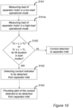
- Figure 10 illustrates a flowchart of a method of a further embodiment, where the load of the motor 23 is measured at different operational modes of the ICE 40, e.g. during the previously discussed high-load operational mode and low-load operational mode, the rationale being that if the measured motor load is the same (or at least similar) for both operational modes, then the conduit 18 must have been detached from the inlet 17 of the separator 1.
- step S101 the load of the motor 23 is measured during a low-load operational mode while in step S101, the load of the motor 23 is measured during a high-load operational mode (or vice versa).
- step S102 the measurements of S101 and S101a would both be determined in step S102 to have the appearance illustrated in e.g. Figure 7a , i.e. TU ⁇ L ⁇ TU', while if the conduit 18 is detached and the inlet 17 is plugged, the measurements of S101 and S101a would both be determined in step S102 to have the appearance illustrated in e.g. Figure 7b , i.e. TL ⁇ L ⁇ TL', and the conduit will be detected in step S103 to be detached.
- Figure 7a i.e. TU ⁇ L ⁇ TU'
- this embodiment even further enables avoiding a situation where a motor load measurement performed during normal operation of the ICE erroneously would indicate the conduit 18 being detached from the inlet 17 of the separator 1.
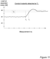
- Figure 11 illustrates an embodiment, where an instant detachment of the conduit 18 is detected, i.e. not a conduit detachment having been performed in advance, but the conduit 18 detaching during ongoing operation of the ICE 40.
- the load of the motor 23 (represented by either power or current consumption) will increase instantly from 40W and exceed the upper load threshold value - in this example set to 55W - at time T 1 . and remain at around 57W.
- the conduit 18 is detected to have detached from the inlet 17 of the separator 1.
Landscapes
- Engineering & Computer Science (AREA)
- Mechanical Engineering (AREA)
- General Engineering & Computer Science (AREA)
- Lubrication Details And Ventilation Of Internal Combustion Engines (AREA)
Priority Applications (3)
| Application Number | Priority Date | Filing Date | Title |
|---|---|---|---|
| EP23181423.7A EP4484721A1 (fr) | 2023-06-26 | 2023-06-26 | Détection du détachement d'un conduit d'un séparateur de gaz de carter de vilebrequin |
| CN202480041953.4A CN121368674A (zh) | 2023-06-26 | 2024-05-23 | 检测曲轴箱气体分离器的管道脱开 |
| PCT/EP2024/064217 WO2025002679A1 (fr) | 2023-06-26 | 2024-05-23 | Détection de détachement de conduit d'un séparateur de gaz de carter |
Applications Claiming Priority (1)
| Application Number | Priority Date | Filing Date | Title |
|---|---|---|---|
| EP23181423.7A EP4484721A1 (fr) | 2023-06-26 | 2023-06-26 | Détection du détachement d'un conduit d'un séparateur de gaz de carter de vilebrequin |
Publications (1)
| Publication Number | Publication Date |
|---|---|
| EP4484721A1 true EP4484721A1 (fr) | 2025-01-01 |
Family
ID=87047952
Family Applications (1)
| Application Number | Title | Priority Date | Filing Date |
|---|---|---|---|
| EP23181423.7A Pending EP4484721A1 (fr) | 2023-06-26 | 2023-06-26 | Détection du détachement d'un conduit d'un séparateur de gaz de carter de vilebrequin |
Country Status (3)
| Country | Link |
|---|---|
| EP (1) | EP4484721A1 (fr) |
| CN (1) | CN121368674A (fr) |
| WO (1) | WO2025002679A1 (fr) |
Citations (4)
| Publication number | Priority date | Publication date | Assignee | Title |
|---|---|---|---|---|
| DE102012014474A1 (de) * | 2012-07-21 | 2014-01-23 | Daimler Ag | Zentrifugalabscheidervorrichtung eines Kraftfahrzeugs, die zumindest einen Teller- und/oder Plattenseparator aufweist |
| EP3428413A1 (fr) * | 2017-07-13 | 2019-01-16 | Bayerische Motoren Werke Aktiengesellschaft | Procédé de surveillance d'un dispositif ventilateur de carter de vilebrequin |
| US20220165105A1 (en) * | 2020-11-20 | 2022-05-26 | Volvo Truck Corporation | Method for diagnosing a part of a crank case ventilation system |
| DE102021003332A1 (de) * | 2021-06-28 | 2022-12-29 | Daimler Truck AG | Verfahren zum Entlüften eines Kurbelgehäuses einer Verbrennungskraftmaschine, insbesondere eines Kraftfahrzeugs |
-
2023
- 2023-06-26 EP EP23181423.7A patent/EP4484721A1/fr active Pending
-
2024
- 2024-05-23 WO PCT/EP2024/064217 patent/WO2025002679A1/fr not_active Ceased
- 2024-05-23 CN CN202480041953.4A patent/CN121368674A/zh active Pending
Patent Citations (4)
| Publication number | Priority date | Publication date | Assignee | Title |
|---|---|---|---|---|
| DE102012014474A1 (de) * | 2012-07-21 | 2014-01-23 | Daimler Ag | Zentrifugalabscheidervorrichtung eines Kraftfahrzeugs, die zumindest einen Teller- und/oder Plattenseparator aufweist |
| EP3428413A1 (fr) * | 2017-07-13 | 2019-01-16 | Bayerische Motoren Werke Aktiengesellschaft | Procédé de surveillance d'un dispositif ventilateur de carter de vilebrequin |
| US20220165105A1 (en) * | 2020-11-20 | 2022-05-26 | Volvo Truck Corporation | Method for diagnosing a part of a crank case ventilation system |
| DE102021003332A1 (de) * | 2021-06-28 | 2022-12-29 | Daimler Truck AG | Verfahren zum Entlüften eines Kurbelgehäuses einer Verbrennungskraftmaschine, insbesondere eines Kraftfahrzeugs |
Also Published As
| Publication number | Publication date |
|---|---|
| WO2025002679A1 (fr) | 2025-01-02 |
| CN121368674A (zh) | 2026-01-20 |
Similar Documents
| Publication | Publication Date | Title |
|---|---|---|
| EP2252776B1 (fr) | Procédé de diagnostic fonctionnel d'un séparateur | |
| US11313262B2 (en) | Control of a centrifugal separator | |
| US6783571B2 (en) | Method and a device for cleaning of crankcase gas | |
| EP3610139B1 (fr) | Procédé permettant de commander la pression de l'huile d'une pompe à huile dans un moteur à combustion et sur un agencement de pression d'huile | |
| US11035264B2 (en) | Internal combustion engine for a motor vehicle | |
| JP2011515612A5 (fr) | ||
| CN101240725A (zh) | 自适应油压故障检测 | |
| WO2019072914A1 (fr) | Moteur à combustion interne et procédé de nettoyage de gaz de carter de moteur | |
| US11828211B2 (en) | Method for operating an active oil separator and device for separating oil | |
| WO2025002679A1 (fr) | Détection de détachement de conduit d'un séparateur de gaz de carter | |
| CN114517737B (zh) | 用于诊断曲轴箱通风系统的一部分的方法 | |
| EP3538747B1 (fr) | Procédé de régulation de l'alimentation en huile d'un moteur à combustion interne | |
| EP4400696B1 (fr) | Procédé d'estimation d'un aspect opérationnel d'un moteur, programme informatique, support lisible par ordinateur, agencement de commande, moteur et véhicule | |
| CN104295341B (zh) | 向曲轴箱外无辅助驱动的窜气移除 |
Legal Events
| Date | Code | Title | Description |
|---|---|---|---|
| PUAI | Public reference made under article 153(3) epc to a published international application that has entered the european phase |
Free format text: ORIGINAL CODE: 0009012 |
|
| STAA | Information on the status of an ep patent application or granted ep patent |
Free format text: STATUS: THE APPLICATION HAS BEEN PUBLISHED |
|
| AK | Designated contracting states |
Kind code of ref document: A1 Designated state(s): AL AT BE BG CH CY CZ DE DK EE ES FI FR GB GR HR HU IE IS IT LI LT LU LV MC ME MK MT NL NO PL PT RO RS SE SI SK SM TR |
|
| STAA | Information on the status of an ep patent application or granted ep patent |
Free format text: STATUS: REQUEST FOR EXAMINATION WAS MADE |
|
| 17P | Request for examination filed |
Effective date: 20250509 |